Chapter 7. Advanced Enterprise Campus Design
This chapter covers the following subjects:
Campus LAN Design and Best Practices: This section covers best practices to consider in campus local-area network (LAN) design.
High Availability Network Services: This section covers high availability design for the campus LAN, from client to access switch to the core and throughout the campus network.
This chapter expands on Chapter 6, “Enterprise LAN Design and Technologies,” covering advanced design of campus LANs. It covers traditional and updated Layer 2 access designs as well as Layer 3 access design. It also covers advanced redundancy solutions, first-hop redundancy protocols, and interbuilding and intrabuilding media technologies.
This chapter covers the following objectives from the ENSLD 300-420 exam:
Design campus networks for high availability
Design multi-campus Layer 3 infrastructures
“Do I Know This Already?” Quiz
The “Do I Know This Already?” quiz helps you identify your strengths and deficiencies in this chapter’s topics. This quiz, derived from the major sections in the “Foundation Topics” portion of the chapter, helps you determine how to spend your limited study time. Table 7-1 outlines the major topics discussed in this chapter and the “Do I Know This Already?” quiz questions that correspond to those topics. You can find the answers in Appendix A, “Answers to the ‘Do I Know This Already?’ Quiz Questions Q&A Questions.”
Table 7-1 “Do I Know This Already?” Foundation Topics Section-to-Question Mapping
Foundation Topics Section |
Questions Covered in This Section |
Campus LAN Design and Best Practices |
1, 3, 4, 6 |
High Availability Network Services |
2, 5, 7–8 |
1. What is true in the Layer 3 access layer design?
There is no need for an FHRP.
There is no need for VLANs in the access layer.
VLANs can span access switches.
The SVIs are defined in the distribution layer.
2. Which of the following methods provide workstation-to-router redundancy in the access layer? (Choose two.)
AppleTalk Address Resolution Protocol (AARP)
Hot Standby Router Protocol (HSRP)
Virtual Router Redundancy Protocol (VRRP)
Dynamic Host Configuration Protocol (DHCP)
3. What is the 20/80 rule?
80% of the traffic is local, 20% is external
20% of the traffic is local, 80% is external
20% of the traffic is reserved for VoIP, 80% for data
20% of the traffic is peer-to-peer, 80% is client/server
4. The summarization of routes is a best practice at which layer?
Access layer
Distribution layer
Core layer
WAN layer
5. A design uses two Layer 2 circuits interconnecting two data centers. Spanning Tree Protocol causes the second circuit to be in blocking state. What technology can you implement to use both circuits?
Fast IP
MST
STP Toolkit
EtherChannel
6. Two workstations are located on separate VLANs. They exchange data directly. What type of application is this?
Client/server
Client/peer
Peer-to-peer
Client/enterprise
7. Which protocol is an IETF standard?
VSS
HSRP
VRRP
GLBP
8. Which solution allows you to expand the user capacity in the access layer without having to replace the existing switch?
VSS
EtherChannel
MEC
Stacking technology
Foundation Topics
Campus LAN Design and Best Practices
LANs can be classified as large-building LANs, campus LANs, or small and remote LANs. A large-building LAN typically contains a major data center with high-speed access and floor communications closets; it is usually the headquarters in a larger company. Campus LANs provide connectivity between buildings on a campus. Redundancy is usually a requirement in large-building and campus LAN deployments. Small and remote LANs provide connectivity to remote offices with a relatively small number of nodes.
Campus design factors include the following categories:
Network application characteristics: Different application types
Infrastructure device characteristics: Layer 2 and Layer 3 switching and hierarchy
Environmental characteristics: Geography, wiring, distance, space, power, and number of nodes
Network Requirements for Applications
A business dictates which applications need to be used, and the network must be able to support them. Applications may require high bandwidth or may be time sensitive. Infrastructure devices influence the design. Decisions on switched or routed architectures and port limitations influence the design. The actual physical distances affect the design. The selection of copper or fiber media may be influenced by the environmental or distance requirements. Table 7-2 describes different application types.
Table 7-2 Application Types
Application Type |
Description |
Peer-to-peer |
Peer-to-peer applications include instant messaging, file sharing, IP phone to IP phone, and video conferencing. |
Client/local servers |
Servers are located in the same segment as the clients or close by, normally on the same LAN. According to the legacy 80/20 workgroup rule, 80% of traffic is local, and 20% is not local. This rule is not followed today. |
Client/data center |
Mail servers, file servers, database servers, and business applications are located in the data center. The network needs to be reliable and provide adequate bandwidth to the data center. |
Client/enterprise edge |
External servers such as mail, web, business-to-business (B2B), and public servers are located in the enterprise-edge where off-net connectivity is located. |
There is a wide range of network requirements for applications, depending on the application type. Networks today are switched and not shared. Data centers require high-capacity links to the servers and redundant connections on the network to provide high availability. With servers now located in data centers, the 20/80 rule is applied. With 20/80, 20% of traffic is local traffic, and 80% of the traffic communicates with servers in the data center.
Costs are lower for peer-to-peer applications and become higher for applications that traverse the network with high redundancy. Table 7-3 summarizes network requirements for applications.
Table 7-3 Network Requirements for Application Types
Requirement |
Peer-to-Peer |
Client/Local Servers |
Client/Data Center |
Client/Enterprise Edge |
Connectivity type |
Switched |
Switched |
Switched |
Switched |
Throughput required |
Medium to high |
Medium |
High |
Medium |
Availability |
Low to high |
Medium |
High |
High |
Network costs |
Low to medium |
Medium |
High |
Medium |
Best Practices for Hierarchical Layers
Each layer of the hierarchical architecture requires special considerations. The following sections describe best practices for each of the three layers of the hierarchical architecture: access, distribution, and core.
Access Layer Best Practices
When designing the building access layer, you must consider the number of users or ports required to size up the LAN switch. Connectivity speed for each host should also be considered. Hosts might be connected using various technologies, such as Fast Ethernet, Gigabit Ethernet, and port channels. The planned VLANs enter into the design as well.
Performance in the access layer is also important. Redundancy and QoS features should be considered.
There are several options for the access layer architectures:
Traditional Layer 2 access layer design
Updated Layer 2 access layer design
Layer 3 access layer design
Hybrid access layer design
Traditional Layer 2 Access Layer
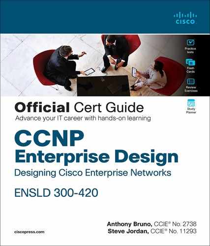
Figure 7-1 shows the traditional Layer 2 access layer. This is the de facto model that has been used for years, where VLANs are defined in the distribution switches, HSRP gateways are configured for the VLANs with active and standby, and the Spanning Tree Protocol root bridge is configured. The access switch is configured as a Layer 2 switch that forwards traffic via trunk ports to the distribution switches. There is no load balancing because Spanning Tree Protocol blocks one of the uplink trunks, so only one uplink is active for each VLAN.
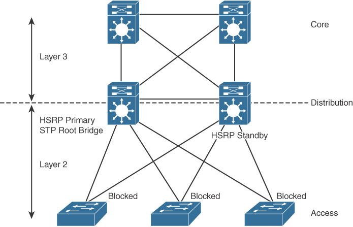
Figure 7-1 Traditional Layer 2 Access Layer Design
Distribution layer switches act as default gateways. Layer 3 links are used between the core and distribution switches with a routing protocol.
Updated Layer 2 Access Layer (Using VSS)
Figure 7-2 shows the updated Layer 2 access layer. In this model, the distribution switches are still the demarcation between the Layer 2 and Layer 3 boundaries. The difference now is that Virtual Switching System (VSS) is configured in the distribution layer. With VSS, the physical distribution switch pair is merged into a virtual switch. VSS is supported on Cisco 4500, 6500, and 6800 Series switches. With VSS, both access switch uplinks are used, doubling the bandwidth from access switches to the distribution pair. The bundled pair is called a Multichassis EtherChannel (MEC), and it creates a loop-free topology. With Gigabit Ethernet uplinks, you have 2 Gbps of uplink bandwidth, and with 10 Gigabit Ethernet uplinks, you have 20 Gbps of uplink bandwidth.

Figure 7-2 Updated Layer 2 Access Layer Design
When VSS is used, there is no need for a first-hop routing protocol (FHRP) such as HSRP. This solution provides faster convergence and higher uplink bandwidth than the traditional Layer 2 access design.
Layer 3 Access Layer
Figure 7-3 shows the Layer 3 access layer. With this design model, the Layer 3 demarcation is pushed to the access layer. The access layer switches have VLANs defined and act as the default gateways. Notice that VLANs are not able to span access switches.

Figure 7-3 Layer 3 Access Layer Design
Layer 3 links are now used from the access layer to the distribution switches to the core. The use of HSRP is not necessary. In this solution, the access layer switches act as default gateways and participate in routing, and there is no need for an FHRP.
Hybrid LAN Access Layer
The hybrid access layer combines the use of Layer 2 switching with Layer 3 at the access layer. In this design, some VLANs are defined in the access layer and others in the distribution layer. There are Layer 3 and Layer 2 links between the distribution switches and the access switches. With the Layer 2 links, Spanning Tree Protocol is still in the network. This design is not the preferred design because it has the added complexity of mixed Layer 2 and Layer 3 access layers per VLAN, but it is usually implemented for various reasons. One reason to implement these solutions might be sensor or security devices requiring a shared VLAN. The disadvantage is that Spanning Tree Protocol is enabled on these VLANs.
Access Layer Designs
Table 7-4 summarizes the access layer designs.
Table 7-4 Access Layer Designs
Access Layer Design Model |
Description |
Traditional Layer 2 access layer |
Layer 2 switch forwards traffic via trunk ports to distribution switches. Spanning Tree Protocol blocks one of the uplink trunks. |
Updated Layer 2 access layer |
Uses VSS and MEC to provide additional uplink bandwidth. |
Layer 3 access layer |
Layer 3 SVIs are defined in the access layer, and there is no need for an FHRP. |
Hybrid access layer |
Layer 3 routing in the access layer and in the distribution layer. |
The following are the recommended best practices for the building access layer:
Limit VLANs to a single closet when possible to provide the most deterministic and highly available topology.
Use Rapid Per-VLAN Spanning Tree Plus (RPVST+) if Spanning Tree Protocol is required. It provides for faster convergence than traditional 802.1d default timers.
Set trunks to ON and ON with no-negotiate.
Prune unused VLANs to avoid broadcast propagation; this is commonly done on the distribution switch. VLAN Trunking Protocol (VTP) version 2 and version 3 automatically prune unused VLANs.
Use VTP Transparent mode because there is little need for a common VLAN database in hierarchical networks.
Disable trunking on host ports because it is not necessary. Doing so provides more security and speeds up PortFast.
Consider implementing routing in the access layer to provide fast convergence and Layer 3 load balancing.
Use the switchport host command on server and end-user ports to enable PortFast and disable channeling on these ports. Alternatively, you can use the spanning-tree portfast default global command.
Use the Cisco STP Toolkit, which provides the following tools:
PortFast: Bypasses the listening/learning phase for access ports.
Loop Guard: Prevents an alternate or root port from becoming designated in the absence of bridge protocol data units (BPDUs).
Root Guard: Prevents external switches from becoming root.
Design Strategy: Used to design a Spanning Tree Protocol priority strategy with the highest priorities hardcoded at the top layers of the Spanning Tree Protocol tree.
BPDU Guard: Disables a PortFast-enabled port if a BPDU is received.
Stacking Access Switches
Stacking is a method of joining multiple physical access switches into a single logical switch. Switches are interconnected by stackwise interconnect cables, and a master switch is selected. The switch stack is managed as a single object and uses a single IP management address and a single configuration file. This reduces management overhead. Furthermore, the switch stack can create an EtherChannel connection, and uplinks can form MECs with an upstream VSS distribution pair.
Distribution Layer Best Practices
As shown in Figure 7-4, the distribution layer aggregates all closet switches and connects to the core layer. Design considerations for the distribution layer include providing wire-speed performance on all ports, link redundancy, and infrastructure services.
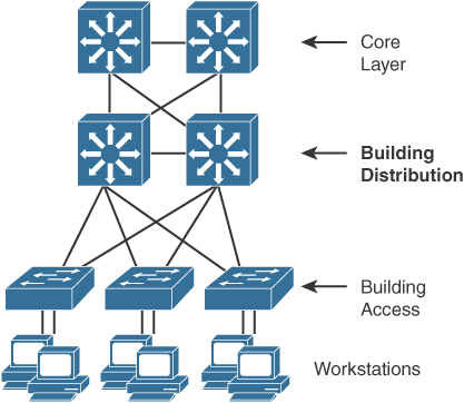
Figure 7-4 Distribution Layer
The distribution layer should not be limited in terms of performance. Links to the core must be able to support the bandwidth used by the aggregate access layer switches. Redundant links from the access switches to the distribution layer and from the distribution layer to the core layer allow for high availability in the event of a link failure. Infrastructure services include quality of service (QoS) configuration, security, and policy enforcement. Access lists are configured in the distribution layer.
The following are recommended best practices at the distribution layer:
Use first-hop redundancy protocols (FHRPs). Hot Standby Router Protocol (HSRP), Virtual Router Redundancy Protocol (VRRP), or Gateway Load Balancing Protocol (GLBP) should be used if you implement Layer 2 links between the Layer 2 access switches and the distribution layer.
Use Layer 3 routing protocols between the distribution and core switches to allow for fast convergence and load balancing.
Only peer on links that you intend to use as transit.
Build Layer 3 triangles, not squares, as shown in Figure 7-5.

Figure 7-5 Layer 3 Triangles
Use the distribution switches to connect Layer 2 VLANs that span multiple access layer switches.
Summarize routes from the distribution to the core of the network to reduce routing overhead.
Use Virtual Switching System (VSS) to eliminate the use of Spanning Tree Protocol and the need for an FHRP.
Core Layer Best Practices
Depending on the network’s size, a core layer might or might not be needed. For larger networks, building distribution switches are aggregated to the core. This is called a collapsed core. This core layer provides high-speed connectivity to the server farm or data center and to the enterprise edge (to the WAN and the Internet).
Figure 7-6 shows the criticality of the core switches. The core must provide high-speed switching with redundant paths for high availability to all the distribution points. The core must support gigabit speeds and data and voice integration.
Figure 7-6 Core Switches
The following are best practices for the campus core:
Reduce switch peering by using redundant triangle connections between switches.
Use routing that provides a loop-free topology.
Use Layer 3 switches on the core that provide intelligent services that Layer 2 switches do not support.
Use two equal-cost paths to every destination network.
Campus Layer Best Practices
Table 7-5 summarizes campus layer best practices.
Table 7-5 Campus Layer Design Best Practices
Layer |
Best Practices |
Access layer |
Limit VLANs to a single closet, when possible, to provide the most deterministic and highly available topology. |
Use RPVST+ if Spanning Tree Protocol is required. It provides the best convergence. |
|
Set trunks to ON and ON with no-negotiate. |
|
Manually prune unused VLANs to avoid broadcast propagation. |
|
Use VTP Transparent mode because there is little need for a common VLAN database in hierarchical networks. |
|
Disable trunking on host ports because it is not necessary. Doing so provides more security and speeds up PortFast. |
|
Consider implementing routing in the access layer to provide fast convergence and Layer 3 load balancing. Or use the Updated Layer 2 access layer design with VSS. |
|
Use Cisco STP Toolkit, which provides PortFast, Loop Guard, Root Guard, and BPDU Guard. |
|
Distribution layer |
Use first-hop redundancy protocols. HSRP, VRRP, or GLBP should be used if you implement Layer 2 links between the access and distribution. |
Use Layer 3 links between the distribution and core switches to allow for fast convergence and load balancing. |
|
Build Layer 3 triangles, not squares. |
|
Use the distribution switches to connect Layer 2 VLANs that span multiple access layer switches. |
|
Summarize routes from the distribution layer to the core layer of the network to reduce routing overhead. |
|
Use VSS as an option to eliminate the use of Spanning Tree Protocol. |
|
Core layer |
Reduce switch peering by using redundant triangle connections between switches. |
Use routing that provides a topology with no spanning-tree loops. |
|
Use Layer 3 switches that provide intelligent services that Layer 2 switches do not support. |
|
Use two equal-cost paths to every destination network. |
VTP Considerations
VLAN Trunking Protocol (VTP) is a Cisco-proprietary protocol that enables central management of the VLAN database. Implementations of VTPv1 and VTPv2 were unstable, causing the whole LAN network to go down in the event that a higher revision switch was inserted into the network. The best practice is to configure all switches in a VTPv2 domain in Transparent mode. In this mode, all VLAN changes are local.
VTP version 3 eliminated the instabilities of the previous versions. However, VTPv3 is compatible with VTPv2 only if you do not use it to propagate private or extended VLANs. If desired, you need to explicitly configure VTPv3 as the default mode in VTPv2.
High Availability Network Services
This section covers designs for high availability network services in the access layer.
Redundancy Models
When designing a network topology for a customer who has critical systems, services, or network paths, you should determine the likelihood that these components will fail and design redundancy where necessary. Consider incorporating one of the following types of redundancy into your design:
Workstation-to-router redundancy in the building access layer
Server redundancy in the data center
Route redundancy within and between network components
Link media redundancy in the access layer
The following sections discuss these types of redundancy.
First-Hop Redundancy for LAN High Availability
Several protocols increase the ability of a workstation to reach its default gateway router on its network segment, including the following:
Hot Standby Router Protocol (HSRP)
Virtual Router Redundancy Protocol (VRRP)
Gateway Load Balancing Protocol (GLBP)
Virtual Switching System (VSS)
The following sections cover these methods.
HSRP
Cisco Hot Standby Routing Protocol (HSRP) provides a way for an IP workstation that supports only one default router to keep communicating on the internetwork even if its default router becomes unavailable. HSRP works by creating a virtual router that has its own IP and MAC addresses. The workstations use this virtual IP address as their default router.
HSRP routers on a LAN communicate among themselves to designate two routers as active and standby. The active router sends periodic hello messages. The other HSRP routers listen for the hello messages. If the active router fails and the other HSRP routers stop receiving hello messages, the standby router takes over and becomes the active router. Because the new active router assumes both the phantom’s IP and MAC addresses, end nodes see no change. They continue to send packets to the phantom router’s MAC address, and the new active router delivers those packets.
The default HSRP timers are 3 seconds for the hello timer and 10 seconds for the dead timer. You can achieve subsecond failover with HSRP by setting the hello timer to 200 milliseconds and the dead timer to 750 milliseconds. It is recommended to configure HSRP with preemption. With preemption, the primary HSRP router reassumes the primary role when it comes back online. HSRP preemption should be explicitly configured because by default it is disabled. HSRP does not support load sharing as part of the protocol specification. In order to use both uplink paths to the distribution switches, different HSRP groups are configured for different VLANs, with the primary router configured for Switch A for some VLANs and the primary router configured for Switch B for other VLANs. HSRP has a native interface tracking mechanism that is used to track an uplink. If the uplink fails, the HSRP priority is reduced.
HSRP also works for proxy ARP. When an active HSRP router receives an ARP request for a node that is not on the local LAN, the router replies with the phantom router’s MAC address instead of its own. If the router that originally sent the ARP reply later loses its connection, the new active router can still deliver the traffic.
Figure 7-7 shows a sample implementation of HSRP.

Figure 7-7 HSRP: The Phantom Router Represents the Real Routers
In Figure 7-7, the following sequence occurs:
Step 1. The workstation is configured to use the phantom router (192.168.1.1) as its default router.
Step 2. Upon booting, the routers elect Router A as the HSRP active router. The active router does the work for the HSRP phantom. Router B is the HSRP standby router.
Step 3. When the workstation sends an ARP frame to find its default router, Router A responds with the phantom router’s MAC address.
Step 4. If Router A goes offline, Router B takes over as the active router and continues the delivery of the workstation’s packets. The change is transparent to the workstation.
VRRP
Virtual Router Redundancy Protocol (VRRP) is a router redundancy protocol defined in RFC 3768. VRRPv2 only supports IPv4. RFC 5798 defines VRRPv3 for both IPv4 and IPv6 networks. VRRP is based on Cisco’s HSRP but is not compatible with it. VRRP specifies an election protocol that dynamically assigns responsibility for a virtual router to one of the VRRP routers on a LAN. The VRRP router controlling the IP addresses associated with a virtual router is called the master, and it forwards packets sent to these IP addresses. The election process provides dynamic failover in the forwarding responsibility in the event that the master become unavailable. This allows any of the virtual router IP addresses on the LAN to be used as the default first-hop router by end hosts. The virtual router backup assumes the forwarding responsibility for the virtual router if the master fails. The default VRRP hello timer is 1 second, and the dead timer is 3 seconds. Unlike in HSRP, VRRP preemption is enabled by default. Similar to HSRP, to configure load balancing, different VRRP groups are configured for different VLANs. VRRP can also be configured to track the uplink to decrement the VRRP priority of the primary router.
GLBP
Global Load Balancing Protocol (GLBP) is a Cisco-proprietary FHRP that allows packet load sharing among a group of routers. GLBP protects data traffic from a failed router or circuit, such as HSRP, while allowing packet load sharing between a group of redundant routers. Methods for load balancing with HSRP and VRRP work with small networks, but GLBP automatically allows for first-hop load balancing on larger networks.
Unlike HSRP, GLBP provides for load balancing between multiple redundant routers—up to four gateways in a GLBP group. It balances the load by using a single virtual IP address and multiple virtual MAC addresses. All the hosts are configured with the same virtual IP address, and all routers in the virtual router group participate in forwarding packets. By default, all routers in a group forward traffic and do load balancing automatically. GLBP members communicate between each other through hello messages sent every 3 seconds to the multicast address 224.0.0.102, User Datagram Protocol (UDP) port 3222.
Benefits of GLBP include the following:
Load sharing: GLBP can be configured in such a way that traffic from LAN clients can be shared by multiple routers.
Multiple virtual routers: GLBP supports up to 1024 virtual routers (GLBP groups) on each physical interface of a router.
Preemption: GLBP enables you to preempt an active virtual gateway with a higher-priority backup.
Authentication: Simple text password authentication is supported.
VSS
Virtual Switching System (VSS) solves the Spanning Tree Protocol unused blocked links problem by converting the distribution switching pair into a logical single switch. With VSS, the physical topology changes because each access switch has a single upstream distribution switch rather than having two upstream distribution switches. The bundled access switch pair is called a Multichassis EtherChannel (MEC), and it creates a loop-free topology eliminating Spanning Tree Protocol. VSS is configured only on Cisco 4500, 6500, and 6800 Series switches.
In Figure 7-8, the two switches are connected to each other via virtual switch links (VSLs), which makes them seem like a single switch. The key benefits of VSS include the following:
Layer 3 switching toward the access layer
Simplified management of a single configuration of the VSS distribution switch
Better return on investment (ROI) via increased bandwidth between the access layer and the distribution layer
No need to configure an FHRP such as HSRP or VRRP
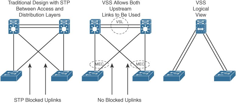
Figure 7-8 Virtual Switching System
Server Redundancy
Some environments need fully redundant (mirrored) file and application servers. For example, in a brokerage firm where traders must access data to buy and sell stocks, two or more redundant servers can replicate the data. Also, you can deploy Cisco Unified Communications Manager (CUCM) servers in clusters for redundancy. The servers should be on different networks and should use redundant power supplies. To provide high availability in the server farm module, you have the following options:
Single attachment: This is not recommended because it lacks link-level redundancy.
Dual attachment: This solution increases availability by using redundant network interface cards (NICs).
Fast EtherChannel (FEC) and Gigabit EtherChannel (GEC) port bundles: This solution bundles 2, 4, or 8 Fast Ethernet or Gigabit Ethernet links to increase bandwidth.
Route Redundancy
Designing redundant routes has two purposes: balancing loads and increasing availability.
Load Balancing
Most IP routing protocols can balance loads across parallel links that have equal cost. Use the maximum-paths command to change the number of links over which the router balances for IP; the default is four, and the maximum is six. To support load balancing, keep the bandwidth consistent within a layer of the hierarchical model so that all paths have the same cost. (Cisco Enhanced Interior Gateway Routing Protocol [EIGRP] is an exception because it can balance loads across multiple routes that have different metrics by using a feature called variance.)
A hop-based routing protocol does load balancing over unequal-bandwidth paths as long as the hop count is equal. After the slower link becomes saturated, packet loss at the saturated link prevents full utilization of the higher-capacity links; this scenario is called pinhole congestion. You can avoid pinhole congestion by designing and provisioning equal-bandwidth links within one layer of the hierarchy or by using a routing protocol that takes bandwidth into account.
IP load balancing in a Cisco router depends on which switching mode the router uses. Process switching balances loads on a packet-by-packet basis. Fast, autonomous, silicon, optimum, distributed, and NetFlow switching do load balancing on a destination-by-destination basis because the processor caches information used to encapsulate the packets based on destination for these types of switching modes.
Increasing Campus Availability
In addition to facilitating load balancing, redundant routes increase network availability.
You should keep bandwidth consistent within a given design component to facilitate load balancing. Another reason to keep bandwidth consistent within a layer of a hierarchy is that routing protocols converge much faster on multiple equal-cost paths to a destination network.
By using redundant, meshed network designs, you can minimize the effect of link failures. With such designs, depending on the convergence time of the routing protocols, it is unlikely that a single link failure will have a catastrophic effect.
You can design redundant network links to provide a full mesh or a well-connected partial mesh. In a full-mesh network, every Layer 3 switch has a link to every other Layer 3 switch, as shown in Figure 7-9. A full-mesh network provides complete redundancy and provides good performance because there is just a single-hop delay between any two campus sites. The number of links in a full mesh is n(n − 1)/2, where n is the number of routers. Each switch is connected to every other switch. A well-connected partial-mesh network provides every switch with links to at least two other routing devices in the network.
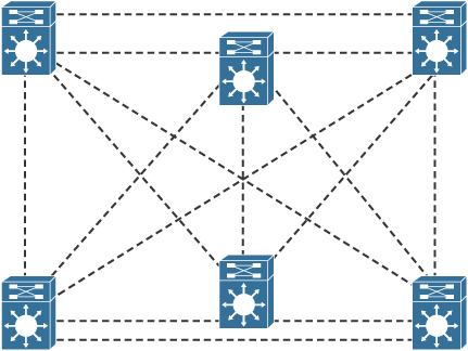
Figure 7-9 Full-Mesh Network: Every Router Has a Link to Every Other Router in the Network
A full-mesh network can be expensive to implement because of the number of links required. In addition, groups of Layer 3 switches or routers that broadcast routing updates or service advertisements have practical limits in terms of scaling. As the number of routing peers increases, the amount of bandwidth and the CPU resources devoted to processing broadcasts increase.
A suggested guideline is to keep broadcast traffic at less than 20% of the bandwidth of each link; this amount limits the number of peer routers that can exchange routing tables or service advertisements. When designing for link bandwidth, reserve 80% of the bandwidth for data, voice, and video traffic so that the rest can be used for routing and other link traffic. When planning redundancy, follow guidelines for simple hierarchical design.
Figure 7-10 illustrates a classic hierarchical and redundant campus enterprise design that uses a partial-mesh design between switches rather than a full-mesh topology.
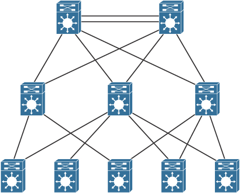
Figure 7-10 Partial-Mesh Design with Redundancy
The following are oversubscription design recommendations:
When implementing data oversubscription, the recommended practice is for 20-to-1 oversubscription for access-to-distribution links.
For distribution-to-core, the oversubscription recommendation is 4 to 1.
You can increase bandwidth by adding more links and aggregating them. Between the campus, these links can be 10 Gigabit Ethernet or 40 Gigabit Ethernet fiber links.
Link Media Redundancy
In mission-critical applications, it is often necessary to provide redundant media.
In switched networks, switches can have redundant links to each other. This redundancy is good because it minimizes downtime, but it can result in broadcasts continuously circling the network; this is called a broadcast storm. Cisco switches implement the IEEE 802.1d spanning-tree algorithm, which aids in avoiding the looping that occurs in broadcast networks. The spanning-tree algorithm guarantees that only one path is active between two network stations. The algorithm permits redundant paths that are automatically activated when the active path experiences problems.
You can use EtherChannel to bundle links for load balancing. Links are bundled in powers of 2 (for example, 2, 4, 8) groups. EtherChannel aggregates the bandwidth of the links. Hence, two 10 Gigabit Ethernet ports provide 20 Gbps of bandwidth when they are bundled. For more granular load balancing, use a combination of source and destination per-port load balancing, if available on the switch. In current networks, EtherChannel uses Link Aggregation Control Protocol (LACP), which is a standard-based negotiation protocol that is defined in IEEE 802.3ad. (An older solution included the Cisco-proprietary PAgP protocol.) LACP helps protect against Layer 2 loops that are caused by misconfiguration. One downside is that it introduces overhead and delay when setting up a bundle.
Redundancy Models Summary
Table 7-6 summarizes the four main redundancy models.
Table 7-6 Redundancy Models
Redundancy Type |
Description |
Workstation-to-router redundancy |
Uses HSRP, VRRP, GLBP, and VSS. |
Server redundancy |
Uses dual-attached NICs, FEC, or GEC port bundles. |
Route redundancy |
Provides load balancing and high availability. |
Link redundancy |
Uses multiple links that provide primary and secondary failover for higher availability. On LANs, uses EtherChannel. |
Large-Building LANs
Large-building LANs are segmented by floors or departments. The building-access component serves one or more departments or floors. The building-distribution component serves one or more building-access components. Campus and building backbone devices connect the data center, the building-distribution components, and the enterprise edge-distribution component. The access layer typically uses Layer 2 switches to contain costs, with more expensive Layer 3 switches in the distribution layer to provide policy enforcement. Current best practice is to also deploy multilayer switches in the campus and building backbone. Figure 7-11 shows a typical large-building design.

Figure 7-11 Large-Building LAN Design
Each floor can have more than 200 users. Following the hierarchical model of building access, building distribution, and core, Fast Ethernet nodes can connect to the Layer 2 switches in the communications closet. Fast Ethernet or Gigabit Ethernet uplink ports from closet switches connect back to one or two (for redundancy) distribution switches. Distribution switches can provide connectivity to server farms that provide business applications, Dynamic Host Configuration Protocol (DHCP), Domain Name System (DNS), intranet, and other services.
For intrabuilding structure, user port connectivity is provided via unshielded twisted-pair (UTP) run from cubicle ports to floor communication closets, where the access switches are located. These are Gigabit Ethernet ports. Wireless LANs are also used for user client devices. Optical fiber is used to connect the access switches to the distribution switches with new networks utilizing 10 Gigabit Ethernet ports.
Enterprise Campus LANs
A campus LAN connects two or more buildings within a local geographic area using a high-bandwidth LAN media backbone. Usually the enterprise owns the medium (copper or fiber). High-speed switching devices minimize latency. In today’s networks, 10 Gigabit Ethernet or 40 Gigabit Ethernet campus backbones are the standard for new installations. In Figure 7-12, Layer 3 switches with fiber-optic media connect campus buildings.
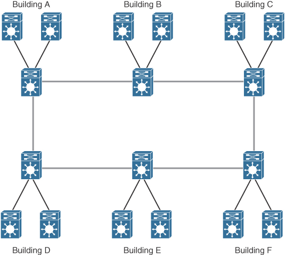
Figure 7-12 Campus LAN
Ensure that you implement a hierarchical design on a campus LAN and assign network layer addressing to control broadcasts on the networks. Each building should have addressing assigned in such a way as to maximize address summarization. Apply contiguous subnets to buildings at the bit boundary to apply summarization and ease the design. Campus networks can support high-bandwidth applications such as video conferencing. Remember to use Layer 3 switches with high-switching capabilities in the campus backbone design. In smaller installations, it might be desirable to collapse the building-distribution component into the campus backbone. An increasingly viable alternative is to provide building access and distribution on a single device selected from among the smaller Layer 3 switches now available.
As a CCNP designer, you should think about interbuilding structure considerations. Modern applications, video requirements, and distance requirements drive the use of fiber technologies for interbuilding connectivity. These include the following:
10GBASE-SR: Multimode fiber for up to 400 meters (short range)
10GBASE-LR: Single mode fiber for up to 10 kilometers (long range)
10GBASE-ER: Single-mode fiber for up to 80 kilometers (extended range)
As shown in the previous sections, each individual module has different requirements. The building access layer is the only layer that uses Layer 2 switching. Both the campus core and the server farm have requirements for high availability and high performance.
Table 7-7 shows network requirements for application types.
Table 7-7 Network Requirements for Application Types
Specification |
Building Access |
Distribution Layer |
Campus Core |
Server Farm |
Technology |
Layer 2 and Layer 3 switches |
Layer 3 switches |
Layer 3 switches |
Layer 3 switches |
Scalability |
High |
Medium |
Low |
Medium |
Availability |
Medium |
Medium |
High |
High |
Performance |
Medium |
Medium |
High |
High |
Cost per port |
Low |
Medium |
High |
High |
Small and Medium Campus Design Options
A medium-sized campus would have between 200 to 1000 end devices. Such a network consists of building access switches that connect to a pair of campus distribution switches, as shown in Figure 7-13.

Figure 7-13 Small and Medium Campus LANs
A small campus would have fewer than 200 end devices. Switches in a small campus might not require much scaling capability. A single distribution switch would connect campus building access switches.
Campus LAN QoS Considerations
For the access layer of a campus LAN, you can classify and mark frames or packets to apply quality of service (QoS) policies in the distribution layer or at the enterprise edge. Classification is a fundamental building block of QoS and involves recognizing and distinguishing between different traffic streams. For example, you distinguish between HTTP/HTTPS, FTP, and VoIP traffic. Without classification, all traffic is treated the same.
Marking (also called coloring or tagging) sets certain bits in a packet or frame that has been classified. Layer 2 has two methods to mark frames for CoS:
Inter-Switch Link (ISL): This method is obsolete.
IEEE 802.1p/802.1Q: This is the recommended method. The IEEE 802.1D-1998 standard describes IEEE 802.1p traffic class expediting.
Both methods provide 3 bits for marking frames. Cisco ISL is a proprietary trunk-encapsulation method for carrying VLANs over Fast Ethernet or Gigabit Ethernet interfaces. It is now an obsolete solution.
ISL appends tags to each frame to identify the VLAN it belongs to. As shown in Figure 7-14, the tag is a 30-byte header and CRC trailer added around the Fast Ethernet frame; it includes a 26-byte header and 4-byte CRC. The header includes a 15-bit VLAN ID that identifies each VLAN. The user field in the header also includes 3 bits for the class of service (CoS).
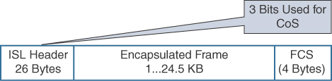
Figure 7-14 ISLFrame
The IEEE 802.1Q standard trunks VLANs over Fast Ethernet and Gigabit Ethernet interfaces, and you can use it in a multivendor environment. IEEE 802.1Q uses one instance of Spanning Tree Protocol for each VLAN allowed in the trunk. Like ISL, IEEE 802.1Q uses a tag on each frame with a VLAN identifier. Figure 7-15 shows the IEEE 802.1Q frame. Unlike ISL, 802.1Q uses an internal tag. IEEE 802.1Q also supports the IEEE 802.1p priority standard, which is included in the 802.1D-1998 specification. A 3-bit Priority field is included in the 802.1Q frame for CoS.

Figure 7-15 IEEE 802.1Q Frame
The preferred location to mark traffic is as close as possible to the source. Figure 7-16 shows a segment of a network with IP phones. Most workstations send packets with CoS or IP precedence bits (ToS) set to 0. If a workstation supports IEEE 802.1Q/p, it can mark packets. VoIP traffic from the phone is sent with a Layer 2 CoS set to 5. The phone also reclassifies data from the PC to a CoS/ToS of 0. With Differentiated Services Codepoint (DSCP) at Layer 3, VoIP bearer traffic is set to Expedited Forwarding (EF) (which implies a ToS set to 5), with binary value 101110 (hexadecimal 2E). Signaling traffic is set to DSCP AF31.
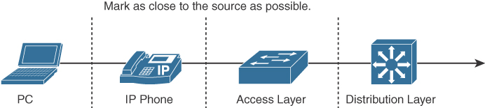
Figure 7-16 Marking of Frames or Packets
As shown in Figure 7-16, switch capabilities vary in the access layer. If the switches in this layer are capable, configure them to accept the markings or remap them. The advanced switches in the distribution layer can mark traffic, accept the CoS/DSCP markings, or remap the CoS/DSCP values to different markings.
References and Recommended Readings
RFC 3768: Virtual Router Redundancy Protocol (VRRP), https://tools.ietf.org/html/rfc3768.
RFC 5798: Virtual Router Redundancy Protocol (VRRP) Version 3 for IPv4 and IPv6, https://tools.ietf.org/html/rfc5798.
10Gigabit Alliance, www.10gea.org.
Cisco, “Cisco Network for High Availability Design Guide,” https://www.cisco.com/c/en/us/td/docs/solutions/Enterprise/Campus/HA_campus_DG/hacampusdg.html.
Cisco, “Cisco Spanning Tree Toolkit,” http://www.cisco.com/c/dam/en_us/solutions/industries/docs/gov/turniton_stpt.pdf.
Cisco, “Spanning Tree from PVST+ to Rapid_PVST Migration,” http://www.cisco.com/c/en/us/support/docs/switches/catalyst-6500-series-switches/72836-rapidpvst-mig-config.html.
Cisco, “Spanning Tree Protocol Enhancements Using Loop Guard and BPDU Skew Detection Features,” http://www.cisco.com/c/en/us/support/docs/lan-switching/spanning-tree-protocol/10596-84.html.
Exam Preparation Tasks
As mentioned in the section “How to Use This Book” in the Introduction, you have a couple of choices for exam preparation: the exercises here, Chapter 13, “Final Preparation,” and the exam simulation questions on the companion website.
Review All Key Topics
Review the most important topics in the chapter, noted with the Key Topic icon in the outer margin of the page. Table 7-8 lists these key topics and the page number on which each is found.
Complete Tables and Lists from Memory
Print a copy of Appendix D, “Memory Tables,” found on the companion website, or at least the section for this chapter, and complete the tables and lists from memory. Appendix E, “Memory Tables Answer Key,” includes completed tables and lists to check your work.
Define Key Terms
Define the following key terms from this chapter and check your answers in the glossary:
first-hop routing protocol (FHRP)
Global Load Balancing Protocol (GLBP)
Hot Standby Routing Protocol (HSRP)
Virtual Router Redundancy Protocol (VRRP)
Q&A
The answers to these questions appear in Appendix A. For more practice with exam format questions, use the exam engine on the companion website.
1. Which of the following is an example of a peer-to-peer application?
IP phone call
Client accessing a file server
Web access
Using a local server on the same segment
2. An enterprise network has grown to span multiple buildings supporting multiple departments. Clients access servers that are in local and other buildings. The company security assessment has identified policies that need to be applied. What do you recommend?
Move all departments to a single building to prevent unauthorized access.
Move all servers to one of the LAN client segments.
Move all servers to a data center server segment that is separate from client LANs.
Move all servers to the building distribution switches.
3. Link redundancy and infrastructure services are design considerations for which layer?
Core layer
Distribution layer
Access layer
Application layer
4. Which of the following are server connectivity methods in the data center?
Single NIC
EtherChannel
Content switch
All of the above
5. A campus network of four buildings is experiencing performance problems. Each building contains 400 to 600 devices, all in one IP subnet. The buildings are connected in a hub-and-spoke configuration back to Building 1 using Gigabit Ethernet with multimode fiber. All servers are located in Building 1. What do you recommend to improve performance?
Connect all buildings in a ring topology.
Implement multiple VLANs in each building.
Move servers to the buildings.
Use single-mode fiber to make the Gigabit Ethernet links faster.
6. Match each application type with its description.
Peer-to-peer
Client/local server
Client/server farm
Client/enterprise edge
Server on the same segment
IM
Web access
Client accesses database server
7. Match each campus design model with its description.
Routed access layer
Traditional Layer 2 access layer
Layer 2 access with VSS
Hybrid access layer
Legacy design
Access layer using Layer 3 capabilities
Improves Layer 2 design
Not recommended.
8. Which network application type is most stringent in terms of the network resources?
Peer-to-peer
Client/local server
Client/data center server farm
Client/enterprise edge
9. Company departments are located across several buildings. These departments use several common servers. Network policy and security are important. Where should servers be placed?
Within all department buildings, and they should duplicate the common servers in each building
Connecting the common servers to the campus core
The data center
Connecting the servers to the distribution layer
10. A large company has a campus core. What is the best practice for the core campus network?
Use triangles.
Use squares.
Use rectangles.
Use point-to-point mesh.
11. A company has five floors. It has Layer 2 switches on each floor with servers. It plans to move servers to a new computer room and create a server farm. What should it do?
Replace all Layer 2 switches with Layer 3 switches.
Connect the Layer 2 switches to a Layer 3 switch in the computer room.
Connect the Layer 2 switches to a new Layer 2 switch in the computer room.
Connect the Layer 2 switches to each other.
12. A link is running at 80% utilization. Business-critical applications are used. What can be done to minimize packet delay and loss?
Implement QoS with classification and policing in the distribution layer.
Add additional VLANs so that the business applications are used on PCs on that VLAN.
Perform packet bit rewrites in the distribution switches.
Classify users in the access layer with different priority bits.
13. Which are four best practices for the access layer? (Choose four.)
Disable trunking in host ports.
Limit VLANs to one closet.
Use PVST+ with multilayer switches.
Enable trunking on host ports.
Use VLAN spanning to speed convergence of Spanning Tree Protocol.
Use VTP Server mode in hierarchical networks.
Use VTP Transparent mode in hierarchical networks.
Use RPVST+ with multilayer switches.
14. Which are three best practices for the distribution layer? (Choose three.)
Use HSRP, VRRP, or GLBP.
Provide fast transport.
Use Layer 3 routing protocols to the core.
Use Layer 2 routing protocols to the core.
Summarize routes to the core layer.
Summarize routes to the access layer.
15. Which are four best practices for the distribution layer? (Choose four.)
Disable trunking in host ports.
Limit VLANs to one closet.
Use HSRP.
Use GLBP.
Use VLAN spanning to speed convergence of Spanning Tree Protocol.
Use Layer 3 routing to the core.
Summarize routes.
Use RPVST+ with multilayer switches.
16. Which are three best practices for the core layer? (Choose three.)
Use routing with no Layer 2 loops.
Limit VLANs to one closet.
Use HSRP.
Use GLBP.
Use Layer 3 switches with fast forwarding.
Use Layer 3 routing to the core.
Use two equal-cost paths to every destination network.
Use RPVST+ with multilayer switches.
17. What is a major requirement if you use a Layer 3 access layer design?
The distribution switches need to be configured as a VSS pair.
The core switches need to support EIGRP.
The access layer switch needs to be able to route.
HSRP needs to be configured on the distribution switches.
18. What is an advantage of using the updated Layer 2 access layer design over the traditional model?
There is an increase in uplink bandwidth.
The updated model adds routing between distribution and access layers.
The access layer switch can route.
Layer 3 load balancing is enabled.
19. Which Cisco IOS feature simplifies spanning-tree topology?
Rapid PVST+
MST
MISTP 802.1W
VSS
20. You implement the updated Layer 2 access layer design. What advantage have you obtained?
Additional uplink bandwidth by using both uplinks
No need for FHRP
Mix of Layer 2 and Layer 3 in the access layer
Spanning Tree Protocol blocking uplink ports
21. You implement the Layer 3 access layer design. What advantage have you obtained?
Additional uplink bandwidth by using both uplinks
No need for FHRP
Mix of Layer 2 and Layer 3 in the access layer
Spanning Tree Protocol blocking uplink ports
22. Which VTP version is enabled by default?
VTPv1
VTPv2
VTPv3
None of the above; VTP version has to be explicitly configured
23. You want to configure subsecond failover for HSRP. What settings do you configure?
Hello timer = 3 seconds, dead timer = 10 seconds
Hello timer = 3 ms, dead timer = 10 ms
Hello timer = 200 ms, dead timer = 750 ms
Hello timer = 200 seconds, dead timer = 750 seconds
24. What are the default timers for VRRP?
Hello timer = 3 seconds, dead timer = 10 seconds
Hello timer = 1 second, dead timer = 3 seconds
Hello timer = 200 ms, dead timer = 750 ms
Hello timer = 1 ms, dead timer = 10 ms
25. What are the default timers for HRSP?
Hello timer = 3 seconds, dead timer = 10 seconds
Hello timer = 1 second, dead timer = 3 seconds
Hello timer = 200 ms, dead timer = 750 ms
Hello timer = 1 ms, dead timer = 10 ms
26. Which protocol allows for load sharing among a group of routers?
HSRP
VRRP
FHRP
GLBP
27. What is the recommended oversubscription ratio for distribution links to core links?
4 to 1
10 to 1
15 to 1
20 to 1
28. What is the recommended oversubscription ratio for access links to distribution links?
4 to 1
10 to 1
15 to 1
20 to 1
29. What is the maximum number of links that can be bundled in an EtherChannel?
2
4
8
16
30. You need to connect sites that are 8 kilometers apart by using fiber. Which media do you recommend?
10GBASE-T
10GBASE-ER
10GBASE-LR
10GBASE-SR
31. You need to connect access switches to the distribution switch pair within a building. Which media do you recommend?
10GBASE-T
10GBASE-ER
10GBASE-LR
10GBASE-SR
32. You need to connect switches in the data center racks. Which media do you recommend?
10GBASE-T
10GBASE-ER
10GBASE-LR
10GBASE-SR