
6 Control strategies for buildings
This section deals with control strategies for whole buildings. The strategy for a complete HVAC system must take into account the interaction between subsystems. The system may operate in several different modes and the condition of each subsystem in every possible mode must be specified. Practical and theoretical design techniques are described which may be used to predict control performance under a range of conditions. The major HVAC systems are summarised with advice on avoiding conflict between subsystems and the successful incorporation of user control. The section ends with some case studies to illustrate successful applications.
6.0 General
A complete HVAC system consists of an assembly of plant modules, many of which interact with each other. Similarly, the control strategy for a whole building includes the strategies of individual plant modules and must take into account all the possible interactions between subsystems. Failure to consider these interactions may result in:
— system instabilities
— high energy consumption
— compromise of safe operation.
6.1 Operating modes
The descriptions of subsystem control strategies in the previous section indicated many of the interactions which should be included in control strategies. In the design of the HVAC and control system for a new building, there are inevitably combinations of subsystems that have not previously been documented and it is essential that the design is theoretically challenged with a range of ‘what if’ scenarios. A variety of possible, likely and unlikely situations should be drawn up and predicted responses of the control system followed through, to ensure that there are no unexpected effects. The BSRIA Library of Control Strategies(1) uses a number of operating modes in which a HVAC plant could operate at different times. Possible modes are listed in Table 6.1. The number of modes will depend on the nature of the HVAC system. A mixed mode system involving heating and cooling, plus mechanical and natural ventilation may have several distinct operating modes during occupancy. The operation of all control strategies in these modes should always be specified unambiguously.
Table 6.1 Operating modes for an HVAC system
| Low outside air temperature interlock (for plant protection) |
| Low return water temperature interlock (for plant protection) |
| Low zone temperature in the conditioned zone (for building fabric and contents protection) |
| Plant shut-down |
| Fan overrun for air systems, pump overrun for water systems |
| Optimum start heating (OSH, boost heating |
| Optimum start cooling (OSC) |
| Night cooling |
| Fire |
| Normal operation during the occupied period, subdivided into: |
| — heating |
| — cooling |
| — natural or mechanical ventilation (mixed mode) |
| — thermal storage operation |
Documentation of a complete control strategy consists of the following:
— schematic diagram of plant
— description of plant
— control strategy
— specification clauses
— BMS points list
— summary of plant operation
— control flowchart.
For reasons of space it is not possible to present a range of full control strategies in this manual. Control strategies may be obtained from a number of sources. Large consultancies maintain their own libraries of strategies which have been found reliable in practice and which may be modified to meet the needs of new design projects. Some of the major manufacturers publish control strategies, which are often of general application(2,3). The major published source of strategies in the UK is the BSRIA Library of System Control Strategies(1). This is a comprehensive document, presenting a large number of control solutions with descriptions of plant operation and control strategy. A standard specification clause is provided with each strategy, together with a full points list. The expectation is that the Library will provide a set of standardised solutions that will enable control systems to be designed, configured and tested in less time than would be required designing from scratch. This Guide has drawn heavily on the Library for the control strategies summarised in the previous section and BSRIA references have been given where applicable.
It is important to choose an HVAC system and control system that are appropriate for the requirements of the building and the operations it supports. There is no advantage in having a sophisticated BMS nor in accumulating information that is not needed and will not be used. Where simple controls, perhaps packaged controllers supplied by plant manufacturers, will perform adequately, they should be used unless there is good reason to install a customised control system. Large modern buildings benefit from a full BMS; the various options for system architecture are dealt with in section 4. The power and flexibility of a modern BMS allows virtually any control strategy to be implemented, and later modified. Changes in user requirements, developments in HVAC technology and evolving policies on energy conservation ensure that innovation and change in building design is a continuing process. Few buildings are identical in their needs to others. This has the consequence that the controls designer is faced with buildings that cannot be satisfied by off-the-shelf solutions. The control strategies for subsystems set out in section 5 have been chosen to be representative of best current practice, but must always be evaluated for suitability for any given building and environmental control system.
The requirements of energy conservation and the desire to reduce or eliminate the need for air conditioning have led to building designs which are intended to operate at the limit of their capabilities during conditions of design weather conditions; it is no longer acceptable to insure against problems by oversizing the plant. This has led to a wide range of buildings, ranging from fully air conditioned sealed buildings to full natural ventilation. In many cases, however, it has been found necessary to introduce ancillary equipment to deal with particular weather or operational conditions. This gives rise to potential control problems in operating the various systems and avoiding conflicts. Practical examples are given in the case studies.
6.2 Design techniques
Various techniques are available which will assist the designer in assessing the performance of possible HVAC plant designs and associated control strategies. The various techniques differ in their methods and application and are described below. The information that may be expected from their use includes:
— performance of building under different operating conditions, especially hot weather
— information on practical problems of installation and operation
— energy consumption
— evaluation of control strategies
— prediction of control performance.
6.2.1 Full scale mock-up
A full scale mock-up of a representative section of the building is constructed. As far as possible it should use the actual materials and items of plant that will be employed in the actual building. The mock-up is placed in a large environmental chamber that can simulate external conditions, including the effects of solar radiation; several such chambers exist in the UK. The effects of indoor activities are reproduced by placing suitable heat sources in the mock-up room. Suitable instrumentation has to be provided to monitor the internal conditions produced. The mock-up is then subjected to a range of external conditions, representing extreme design conditions and a number of intermediate conditions. The HVAC installation is used to control the indoor conditions, which are recorded and evaluated. The procedure allows the designer to:
— show the visual appearance of the finished internal space
— investigate the performance of the HVAC system
— evaluate the control system and its strategy
— ensure that all components can be installed as planned and so obviate problems on site.
Where the cost of a mock-up can be justified, it has proved beneficial to all parties involved in the building project. The use of mock-ups is usually restricted in practice to room-height sections. Where it is required to predict the performance of tall atrium type structures, recourse must be made to analogue or mathematical modelling.
6.2.2 Analogue modelling
Air movement in convective flow may be modelled in a water tank, using salt solutions of varying concentration to represent air at different temperatures(4,5). The model is operated upside down; dense salt solution moves down through water in a way analogous to the upward movement of warm air. A scale model of a section of the building is constructed out of Perspex and mounted upside down in the test tank. Coloured salt solution is injected to represented heat sources and its movement under convective flow is recorded. The technique has been used successfully to evaluate the performance of natural ventilation systems and their control by opening and closing vents(6) but has not received widespread application.
6.2.3 Mathematical modelling
Computer-based mathematical modelling may be used to simulate the performance of a building in considerable detail. Several software applications are available and may be purchased or used via a bureau. General advice on the application of models is given in CIBSE AM11(7). The first step is to input a geometrical model of the building. This includes the building dimensions, thermal properties of the constructional elements, and the orientation and location of the building. The HVAC plant is added; separate modules exist which model the performance of common plant and control systems. Internal heat production and occupancy schedules over the year are set up. The model may then be run to produce predictions of temperatures and energy flows, using detailed weather data for the location and season of interest. Air movement is modelled using the technique of computer fluid dynamics (CFD). This has found considerable application in the investigation of naturally ventilated buildings. The models usually operate in time steps of 1 h and so cannot be used to investigate the finer points of control dynamics. The models are most useful in predicting building performance in extreme weather conditions and establishing whether internal conditions will be found acceptable in hot weather. The ability of the models to allow for the effects of thermal mass on peak temperature is of particular value in this context.
Control strategies may be evaluated using mathematical models. It is sometimes found that control criteria may be relaxed without causing any appreciable discomfort, due to the stabilising effects of the building thermal mass. This can lead to worthwhile savings in energy consumption. Models have also been found of real value in establishing effective night cooling strategies and the operation of mixed mode systems.
6.2.4 Emulation
An emulator for a building energy management system consists of a simulation of a building and its HVAC system which may be connected to a real BMS. The real BMS controls the simulated building as if it were real, transmitting control signals and receiving simulated information back as the simulated building responds to its actions. Since an actual BMS controller is used, with its own time characteristics, it is necessary that the simulated building responds at the same rate as the real building. An emulation run therefore operates in real time, e.g. it will take a week to emulate a week's building operation. An emulator can be used for:
— evaluating the performance of a BMS
— training of BMS operators
— assisting in the development of new control algorithms
— fine tuning the control parameters.
An advantage of using an emulator is that a BMS may be tested with any type of building and HVAC system for which a simulation model is available, and tests can be run on different BMS under identical conditions. Since a real BMS is used, it is not necessary to know the algorithms employed, so that products from different manufacturers may be compared without compromising any proprietary information about the control strategies. The building simulation model is of fundamental importance for the emulation technique. As well as modelling the thermal response of the building, the dynamic behaviour of the controls and actuators must be modelled realistically; this is a more stringent requirement than is found with the mathematical models described in 6.2.3 above. Operation of plant is described in great detail and the emulation exercise may be used to predict reversals and travel of actuators as an indicator of potential maintenance costs. Six emulators were developed for an IEA exercise and are described by Lebrun and Wang(8). They worked well but have not yet found widespread application.
6.3 Whole-building HVAC systems
Table 6.2 lists some major types of HVAC system used in modern buildings with some of their characteristics. Many variations on the basic systems are possible. Control strategies for the subsystems involved have been dealt with in section 5. The designer must consider how the different components of the HVAC system may interact under different operating conditions and ensure that the control system will maintain economic and effective operation under all conditions.
6.3.1 VAV and perimeter heating
This is a widely used combination. Conditioned air is supplied to all parts of the space via the VAV boxes. The proportion of recirculated to outdoor air in the air supply is controlled to ensure that the correct amount of ventilation air is maintained against variations in supply air volume. Temperature control in the zone supplied by a group of terminal units is provided by varying the air flow though each box. Heating may be provided via the terminal unit by fitting the box with a reheat coil, which is supplied with LTHW. The relevant control strategies are set out in Section 5. It is common to provide heating by conventional LTHW radiators or other room heat emitters. This has advantages:
— There is no water supply in the ceiling.
— The heat is supplied where required to counteract perimeter heat loss, especially under windows.
— There is better heat distribution from radiators than from the ceiling, especially at low air flow rates.
The control strategies for the combined system present no great problems. The perimeter heating LTHW flow should be weather compensated. It may be necessary to fit separate controls on different facades where there are large differences in heat loss or insolation. Thermostatic radiator valves will give extra control if required; they may be fitted in addition to, but not instead of, compensated flow temperature. Given effective control of the perimeter heating, it is not necessary to interlock the VAV cooling and the heating to prevent simultaneous operation. With a deep building, perimeter heating may be necessary to maintain comfort in the perimeter zone while the central zones require cooling. Boost heating during optimum start is provided by setting the perimeter heating flow temperature to maximum, with the VAV system off or on full recirculation.

6.3.2 Fan coil units
Fan coil units are available in a wide range of configurations, including underfloor units, console units designed to go on the wall or under windows, to the common type installed in a ceiling void. Units are connected to a supply of hot and chilled water. The distribution of water round a building is simpler and takes less space than the distribution of conditioned air. This makes the installation of fan coil units more flexible than that of a VAV system. FCUs are to be found in all types of building and control systems range from a local thermostat controlling fan operation to a fully integrated whole-building system. Control of individual FCUs was dealt with in 5.10; here, we consider the implications of integration.
The FCUs themselves recirculate room air, heating or cooling as required to maintain the room air set point. Ventilation air is provided by a central air handling unit which supplies 100% outdoor air at controlled temperature and usually controlled humidity. Incorporating the temperature of the primary supply air in the control strategy allows energy savings to be made by controlling the operation of the heat exchanger to exploit free cooling. Fan coil units have no provision for dehumidification other than moisture condensing on the cooling coil. Fan coil units must therefore always be provided with a condensate tray and a means to remove any condensate. In general, it is best to avoid running an FCU with a wet coil, especially when the unit is mounted above a false ceiling where the results of any failure of the condensate removal will be a problem. The preferred method is to deal with the latent load by dehumidifying the primary outdoor air to control room humidity at the desired level; this will normally be sufficient to prevent condensation on the FCU cooling coil. The usual practice is to duct the primary supply air to each FCU, where it is mixed with the recirculated room air by the unit fan. It is also possible to distribute ventilation air through independent terminals. This may have advantages where it is required to maintain maximum flexibility for possible repositioning of the FCUs at a later date, or where the FCUs are only used during the cooling season.
In an integrated system, each intelligent fan coil unit incorporates its own controller which communicates with the BMS. Room temperature set points and time schedules may be set remotely for each unit or group of units acting together. Once of the disadvantages of fan coil units is the potential degree of maintenance required and the disruption involved in identifying and servicing faulty units which are distributed throughout the occupied space. The BMS is used to give warning of any failures or routine maintenance needed, such as the need for a filter change. A fan coil system incorporates many small water control valves, which are susceptible to sticking or blockage. It is possible to incorporate checking routines in the BMS. Each valve is driven fully open and closed in turn, and the appropriate response of the discharge air temperature is checked.
Figure 6.1 shows an air handling unit for a fan coil system, which supplies 100% outdoor air to all room units. A heat exchanger is incorporated to transfer heat between exhaust and outdoor intake air. The air is supplied at constant flow rate during the occupancy period; the extract fan is interlocked to operate at the same time. The supply air humidity is controlled to maintain the zone humidity at a level which will provide comfort and prevent, or at least minimise, condensation on the fan coils. This is typically controlled using an RH sensor in the extract. Supply air temperature may be controlled to be near the desired zone temperature, or scheduled to the outside air temperature; this will allow full advantage to be taken of any free cooling. A suitable schedule is that the supply air temperature should have a maximum temperature of 22ºC when the outside air is at 12ºC or below, and a minimum temperature of 14ºC when the outside air is above 21ºC, with a linear relation in between these values. The heat recovery is operated according to the strategy in Table 5.5 for maximum efficiency.
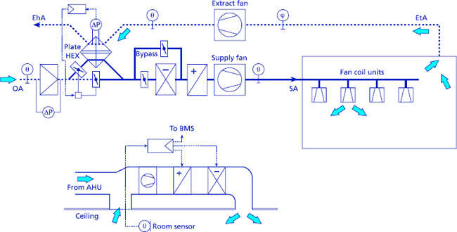
Figure 6.1 Integrated fan coil unit system. The supply air temperature is scheduled to outside temperature. Control connections not shown
Further economies may be made by resetting the flow temperatures of the LTHW and CW to the coils. This strategy requires information to be made available to the BMS on the position of the heating and cooling valves on each FCU. The temperature of the LTHW is reset so that at least one heating valve is fully open while maintaining the required room temperature in all zones. Similarly, the chilled water flow temperature is reset so that at least one cooling valve is fully open. This strategy ensures that the water being circulated to the coils is neither hotter nor cooler than required to maintain the desired conditions. Some care must be exercised when employing this type of strategy, which depends on a large number of logical criteria all being satisfied. A single sensor failure or incorrectly adjusted set point will prevent satisfactory operation. A full control strategy for a fan coil unit system is given in BSRIA Library of System Control Strategies, 3.16.3(1).
6.3.3 VRF systems
Variable refrigerant flow systems provide zone heating and cooling by means of indoor units which are connected via refrigerant lines to the group outdoor unit. Control strategies for VRF systems were set out in 5.13.1. The VRF indoor units do not provide ventilation air and this has to be provided separately. For some applications, such as hotel rooms, it may be adequate to use simple extract ventilation. In general it is better to provide full mechanical ventilation with controlled supply and extract. Manufacturers of VRF systems provide mechanical ventilation with heat recovery (MVHR) systems which may be used in conjunction with the indoor units to provide both temperature control and ventilation. The MVHR unit contains supply and exhaust fans, a cross-flow heat exchanger, filter and a bypass damper which can allow the air to flow straight through and bypass the heat exchanger. The unit is fully ducted and the supply air may be led to conventional diffusers or connected to the indoor units, where it mixes with the recirculated room air being heated or cooled. Each MVHR unit provides sufficient air for several indoor units.
When operating as an independent ventilation system, the unit has its own controller, offering a selection of fan speeds and heat exchange or bypass operating modes. The mode may be selected manually or automatically, based on the outdoor air and extract temperatures. Where the unit is connected to the indoor VRF units, the control may be integrated with the VRF control system, using the manufacturer's proprietary network. The modular nature of VRF systems means that the system may be extended to provide temperature control and ventilation for a large building. Humidity control is not provided in the ventilation units; some dehumidification is provided by the room units when cooling in conditions of high humidity.
6.3.4 Chilled ceiling and displacement ventilation
The range of systems coming under the general description of chilled ceilings can be divided into three groups, with different operating characteristics:
— Chilled panels. A chilled ceiling panel presents a flat surface to the room below. The rear surface of the panel is insulated and there is no requirement for air circulation behind the panel. Cooling is over 50% by radiation.
— Passive chilled beam. The chilled beam contains a cooling coil designed to cool air flowing down through it. Room air circulates up behind the beam and down through it by natural convection. Higher cooling loads are possible than with chilled panels and cooling is about 80% convection. Some beams are designed to present a cool surface to the room, enhancing the radiant proportion.
— Ventilated chilled beam. The beam contains an air duct which supplies the room ventilation air. The supply is 100% outdoor air and is cooled and possibly dehumidified. High velocity nozzles inject air into the beam, which induces additional room air flow thorough the cooling coil. This increases the cooling capacity of the beam over that of a passive beam.
Chilled ceilings and beams provide an effective way of producing comfort cooling in buildings with modest heat loads. Ventilation air is provided independently and this gives the opportunity of introducing mixed mode ventilation, where natural ventilation can be used at appropriate times. Mechanical ventilation with conditioned outdoor air is provided in the heating and cooling seasons; natural ventilation may be used if desired when the outside conditions are suitable. The usual form of mechanical ventilation is a form of displacement ventilation, where the air is introduced at floor level; the use of swirl diffusers ensures that air velocities fall rapidly away from the diffusers and do not cause draughts. In an ideal displacement ventilation system, the air moves steadily up through the occupied zone, taking heat and pollutants with it, to be extracted at high level. By this means, a high ventilation efficiency, potentially greater than one, can be achieved. An air temperature and air quality gradient can be achieved, whereby the occupants are in the clean cool part of the gradient, with air quality worsening at high level. This is in contrast to mixing air distribution, which gives average conditions over the whole space.
In practice, true displacement ventilation is difficult to achieve with a radiant ceiling and impossible with a chilled beam. The chilled beam provides convective cooling, with cooled air falling back into the occupied zone and mixing with the incoming ventilation air. The effect is less marked with a radiant ceiling, which cools largely by radiant exchange with the warmer surfaces in the room(9,10). Some typical chilled ceiling combinations are shown in Table 6.3, with relevant outline strategies.
Chilled ceilings are normally arranged with a separately controlled perimeter zone. Perimeter heating using conventional LTHW radiators is used to counteract perimeter heat loss and any downdraught from windows and is controlled using weather-compensated flow temperature as described in 6.3.1 for VAV systems. A large space will require perimeter heating at the same time as central zone cooling to maintain comfort near windows. Where the radiators are compensated, it will not always be necessary to interlock the perimeter ceiling and radiator to prevent simultaneous heating and cooling. Where a ventilated beam is used incorporating heating coils, an interlock must be present.
Table 6.3 Chilled ceiling systems
| Chilled panel | Passive beam | Ventilated beam | |||
| Cooling | System | Chilled panel | Coil in beam | Coil in beam | |
| Chilled water | 14°C | 14°C | 14°C | ||
| Control | Water flow on/off | Water flow on/off | Modulate water flow | ||
| Heating | System | Radiators | Radiators | Coil in beam | |
| Control | Compensated flow | Compensated flow | Modulated flow | ||
| Ventilation | System | Floor diffusers | Floor diffusers | Duct in beam | |
| Air supply | 18–22°C | 18–22°C | 14–18°C | ||
| Control | Constant volume | Constant volume | Constant volume | ||
| Interlocks | Heat/cool | No | No | Yes | |
| Windows or presence | If desired | If desired | If desired | ||
| Condensation prevention | All systems | Raise chilled water temperature above dewpoint or dehumidify ventilation air. Plus condensation detection | |||
6.3.5 Natural and mixed mode systems
The design of mixed mode and naturally ventilated buildings is closely integrated with that of the building itself. Provision of air flow paths, control of solar gain and the need to provide adequate thermal mass, all influence the building shape and layout. Mixed mode and naturally ventilated buildings tend to be one-off designs, with unique control solutions. Such buildings are likely to include a number of controlled devices, relating to solar control, lighting, heating and mechanical ventilation and perhaps cooling. These controlled devices are operated by a combination of automatic and occupant control. There is a danger, borne out by experience, that subsystems may interact in such a way to give unsatisfactory control and excessive energy consumption. Every attempt must be made to anticipate and design out potential problems.
Full occupant control is only feasible in small cellular offices, where the control choices have limited effect on the rest of the building. The use of a weather-compensated heating circuit will avoid the worst excesses of the window-open/heating-on problem, and simple timeswitches and presence detection will limit excessive use of lighting. Most naturally ventilated buildings incorporate openable windows and other forms of occupant control. Direct control is appreciated by occupants and should lead to greater satisfaction. However, not too much should be expected of occupant control as regards optimum operation of a large building. Operation of a controlled device may have an effect remote from the occupant who, by reasons of proximity, has ‘ownership’ of the controlled device. For instance, the opening of leeward windows is necessary for cross-ventilation in a large building, but will have little effect on comfort nearby. There is therefore little incentive for anyone near the window to open it. While it is desirable to delegate as much control as is practical to occupants, it is not reasonable to expect them to take responsibility for the efficient operation of the whole building. The ability to take an action in response to discomfort, perhaps by opening a window, is valued. The requirement to operate windows for the benefit of staff in a remote part of the zone is unlikely to be carried out efficiently.
Most mixed mode buildings are of complementary design and are designed to operate under a concurrent or changeover strategy(11). A concurrent system uses permanent mechanical ventilation which runs continuously to provide sufficient outdoor air for ventilation purposes. Occupants are free to open windows to provide additional cooling when needed. The natural and mechanical systems complement each other and simultaneous use is possible without conflict. A changeover mixed mode strategy aims to operate the building using the most efficient combination of available systems. The BMS selects the appropriate operating mode and enables or inhibits the relevant systems. There may be several modes, depending on season, use of building or time of day. The BMS must change from one operating mode to another in such a way that continuous control is provided and without being obvious to the occupant. Control of particular devices may be passed from manual occupant control to automatic control and this must be done without antagonising the building users. Control decisions made by the BMS must be acceptable to the occupants and appear sensible; if not, the building users may expend considerable ingenuity in outwitting the BMS. Locking windows which shut when external air temperature exceeds internal temperature may not be acceptable to the occupants in the building. Situations where the BMS promptly overrides an action taken by an occupant will be disliked and lead either to the abandonment of any involvement in environmental control or an antagonism to the building and the organisation which it represents(12).
6.4 Case studies
The control solution adopted for any individual building is likely to have its own particular characteristics. Choices are made by the designer to resolve problems or take advantage of opportunities presented by the project. It is therefore impossible for this Guide to list a comprehensive selection of whole-building control strategies that would cover all, or even most, BMSs. The remainder of the chapter presents some case studies of building management systems that have been successfully applied to actual buildings. The studies cover a range of building types and HVAC systems. The description of the control systems, while brief, serve to demonstrate the wide range of BMS applied in practice and serve to bring out some useful lessons.
6.4.1 Retrofit using a modular control system
| Building Type |
Greenway School, Horsham Junior School |
Greenway School in Horsham teaches 400 7–11-year-old children in a group of buildings, comprising a main building and six classroom huts. Heating and hot water to the main building are provided by three gas-fired boilers and independent gas-fired convectors are used to heat the classroom huts. It was decided to keep the existing heating system and upgrade the controls to provide overall control from a single position, but allow individual teachers some flexibility in setting temperatures.
A modular control system was installed, consisting of one master and eight-slave zone controllers, plus a boiler sequence controller and the necessary sensors and actuators. All components are interconnected via a simple two-wire bus, employing the LonWorks protocol. The master zone controller is located in the school secretary's office and is used to set the time schedule and temperatures for all zones. In addition, the controller provides optimum start and weather compensation. The individual zone controllers in each classroom give a temperature display and allow limited alteration of set point.
The control system provides central control of time scheduling, bringing the entire system under central control and preventing any individual heaters being left on by mistake. No specialist knowledge is required for operation.
The modular controls chosen proved easy to install using the bus system. The straightforward interface allowed operation by non-technical staff.
6.4.2 Remote control of a group of homes for the elderly
| Building Type |
10 elderly people's homes, Clwyd Residential homes |
Clwyd Council operates a centralised BMS bureau and energy monitoring and targeting service, which has been successful in producing an overall reduction of 25% in energy consumption in buildings serviced. It was decided that a group of elderly people's homes operated by the social services department offered scope for improved control and monitoring. The ten homes are of modern construction and heated by a conventional boiler serving radiators and hot water services.
The energy conservation unit applies a three-year payback criterion for improvement schemes, which required a low cost solution. Each home was retrofitted with a stand-alone energy management system. This provided time and temperature scheduling, optimum start and weather compensation, including room reset control. Boiler operation includes sequencing control and improvement of efficiency by variable minimum off-time control, which increases the off-time during cycling as the flow and return temperatures get closer together, i.e. at light loads. Control of hot water services is also provided. Water heating periods are matched to kitchen operating times and the boiler flow temperature is adjusted as the duty moves between space and water heating. The controllers contain their own data-logging features and a modem, which allows communication between the controller and the BMS bureau over the public service telephone network. The controller can send routine data files automatically to the central PC and initiate alarms messages if required. If desired, alarms can be sent automatically to a fax machine. Staff at the central bureau may remotely view plant status or take direct control of operation.
The previous heating systems were poorly controlled and installation of the improved controllers produced reductions in gas consumption of between 20 and 30%. In addition to the savings produced by improved controller performance, the information provided by the monitoring and targeting service allowed other energy savings to be identified.
Lesson. The use of stand-alone controllers with built-in communication facilities allowed professional energy management of a number of dispersed buildings to be installed at low cost.
6.4.3 Low energy university building with fabric storage
| Building | Elizabeth Fry Building, University of East Anglia |
| Type | Two floors of cellular offices and two floors of lecture and seminar rooms, plus kitchen and dining room |
The building is highly insulated and well sealed. No mechanical cooling is provided. Supply ventilation air is tempered by passing though hollow core floor and ceiling slabs. A highly simplified diagram of the system as applied to the office area is shown in Figure 6.2. Gas-fired boilers provide heat to the AHU when required and a high efficiency regenerative heat exchanger is employed for heat recovery. Full fresh air ventilation is used during occupied hours. All windows are openable without restriction on their use. Ventilation to the lecture theatres is by variable speed fan controlled by the CO 2concentration of the extract air. This compensates for the variable occupancy and gives substantial savings in fan running costs.
The building is thermally very stable and control of zone temperature is achieved by controlling the core temperature (Table 6.4), measured near the air outlets.
The Elizabeth Fry Building has successfully achieved a combination of very low energy consumption and high occupant satisfaction. The hollow core slab system achieves very steady temperatures and comfortable summer conditions without the use of air conditioning.

Figure 6.2 Hollow core slab system used in Elizabeth Fry Building. Full fresh air ventilation is used at all times during occupancy. Heat recovery may be deactivated
There were initial teething problems caused by inadequate controls and the lack of a proper BMS, which did not allow the maintenance staff to understand the operation of the various systems. Subsequently, new controls were fitted and integrated into the campus-wide BMS system. The availability of performance data was vital in allowing the control strategy and settings to be fine tuned and simplified. The commissioning and handover period extended over the first two years of occupancy. Cooperation between the building manager, controls specialist and the design team resulted in a well-configured system with a simple control strategy(10,13).
6.4.4 Mixed mode R&D facility using chilled beams
| Building Type |
Hewlett Packard, Building 3, Bristol Three-storey open plan building housing offices and computing laboratories |
This building provides a research and development facility for up to 450 staff and was completed during 1998(14). The three storeys provide two floors of open plan flexible space for offices and laboratories (Figure 6.3). The ground floor contains a presentation area, meeting rooms and a large coffee shop, which provides a centre of social interaction. A central atrium forms a central street; on the upper floors, glazed balustrades surround the central space, giving a feeling of light and openness.
The nature of the business activity produces a relatively high small power load of about 40 W/m2. This demands mechanical cooling, which is provided by chilled beams. There is no natural ventilation. The building is well sealed, achieving a low leakage value with the assistance of concrete floor and ceiling slabs, which also provide thermal mass. Supply air is provided as 100% outside air through floor diffusers; extract is via air handling luminaires. The supply air is conditioned in the central AHU and delivered to the zones at a constant temperature of 19ºC, though this may be reset over the range 19–21ºC if required in hot or cold weather. Full recirculation is used during warm-up. Supply air can be dehumidified to maintain the dewpoint below 12ºC, to avoid condensation forming on the chilled beams; in this building no facility for humidification is provided. Perimeter heating to offset losses at the windows is provided by LTHW radiators. Additional radiators are fitted at high level in the atrium to prevent cold downdraughts in winter from the atrium roof. There is no external solar shading. Internal venetian blinds are fitted and a central blind controller sets the position and angle of the blinds. In strong sunshine, the blinds heat up and produce a convective updraught of warm air. To prevent this causing problems for the chilled beams, the perimeter is decoupled from the internal zone by drawing the air through a grille circling the perimeter. The air passes over a large cooling coil and returns to the occupied space. In hot weather, it is possible for hot air to accumulate under the atrium roof and work its way down into the second-floor offices. To prevent this, chilled water can be passed through the high level radiators.
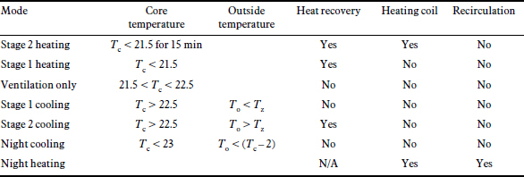
Tc = Core temperature; To = Outside temperature; T2 = Zone temperature.

Figure 6.3 Cross-section of Hewlett Packard Building 3, showing chilled ceiling and displacement ventilation(14)
The building has an advanced IT network. This is designed to be innovative and is subject to change. It was therefore decided to maintain the control network entirely independent of the IT system. The innovative nature of the system decided the consultants to construct a full scale mock-up of the perimeter zone to evaluate the control system under a range of operating conditions. These tests demonstrated a potential instability, where the perimeter radiators and chilled beams oscillated between heating and cooling. This was resolved by altering the control set points. Air movement in the atrium was investigated using CFD modelling, which demonstrated the need to use high level radiators, both to prevent downdraughts in winter and to limit overheating in summer. The thorough investigation of control behaviour at the design stage proved invaluable in resolving potential problems.
6.4.5 Terminal 2, Manchester Airport
| Building Type |
Terminal 2, Manchester Airport Large airport terminal |
Manchester Airport's second terminal was completed in 1994. It was decided to use an integrated BMS which would provide a facilities management system which, in addition to controlling the extensive HVAC system, would interface with many other systems and provide the following control and monitoring:
— Control
— HVAC: VAV systems in terminal, shops and offices
— lighting
— airport services: telephone system, baggage handling, escalators
— runway drainage
— access control: to plant rooms.
— energy: electricity, water, gas and provide billing
— life safety: fire fighting, smoke detection
— apron services: ground power, battery charging.
The system is designed to provide full multi-user functionality and operate using the airport's existing fibre optic structured wiring system. It utilises a two-tier network topology. The top tier sits on the Manchester Airport fibre optic network; master controllers are located in plant rooms and workstations in various control rooms are connected directly to the network. The lower tier is then run locally to pick up controllers located in motor control centres, substations or VAV boxes, using coaxial cable or UTP as appropriate.
As far as possible, control systems were designed as generic copies of existing systems, allowing the use of existing reliable software. Commissioning was facilitated by positioning the site team's temporary buildings so that connections could be made to the structured wiring system at an early stage. This provision of a temporary location for the supervisor allowed programs to be downloaded into the controllers as soon as the network was complete. The system has proved capable of expansion. It now comprises over 8000 points and 1000 graphics panels. It can cope with multi-users. Touchscreen display panels are installed in shop and office areas, allowing adjustment of a restricted range of set points and variables.
6.5 Summary
Efficient operation of a building requires that the subsystems do not interact wastefully. All possible operating modes of the building should be listed systematically together with the operating states of the component subsystems. This will assist in identifying unsatisfactory situations, e.g. where heating and cooling may be operating simultaneously. The involvement of the building occupant in the operation of control devices can bring benefits in increased comfort and satisfaction with the environment. However, concurrent operation of automatic control systems and occupant action may produce dissatisfaction if the user is overridden by the automatic system. Careful attention is required to produce a combination of user and automatic control that is neither wasteful nor over-complex and self-defeating.
Several techniques are available to predict building performance, either analogue modelling, full scale mock-up, or various mathematical modelling techniques. Modelling can anticipate potential control problems and allow them to be corrected at the design stage. The section summarises the more common combinations of heating, cooling and ventilation and discusses the requirements for them to work together satisfactorily.
Design lessons are illustrated by a range of case studies, which range from simple heating-only classrooms to large complex integrated buildings. The choice of the appropriate system and strategy for the task in hand is emphasised.
References
1 Martin A J and Banyard C P Library of system control strategies Applications Guide AG 7/98 1st ed (Bracknell: Building Services Research and Information Association) (1998)
2 Honeywell Engineering manual of automatic control SI ed (Minneapolis: Honeywell Inc.) (1995)
3 Siemens MSR Planungshandbuch (CD-ROM) (Karlsruhe: Siemens AG) (1997)
4 Lane-Serff G F, Linden P F et al. Laboratory and mathematical models of natural ventilation Roomvent’90 Proc. 2nd International Conf. Paper A2-7 (Oslo, Norway: Norsk VVS) (1990)
5 Etheridge D and Sandberg M Building ventilation theory and measurement (Chichester: Wiley) (1998)
6 Brister A Cable Talk Building Services. CIBSE Journal 15(11) 22–26 (1993)
7 Building energy and environmental modelling CIBSE Applications Manual AM11 (London: Chartered Institution of Building Services Engineers) (1998)
8 Lebrun J and Wang S Evaluation and emulation of building energy management systems Synthesis report AN17-SR1 (Liege, Belgium: University of Liege) (1993)
9 Alamdari F and Eagles N Displacement ventilation and chilled ceilings TN 2/96 (Bracknell UK: Building Services Research and Information Association) (1996)
10 Bunn R Chilling lessons Journal of the Chartered Institute of Building Services 17(5) 37–38 (1995)
11 Mixed mode ventilation systems: CIBSE Applications Manual (London: CIBSE) (1999)
12 Probe 18: Portland Building Building Services Journal 21(1) 35–40 (1999)
13 Probe 14: Elizabeth Fry Building Building Services Journal 20(4) 37–43 (1998)
14 Pearson A HP sourced Building Services Journal 19(12) 12–16 (1997)