
8 Management issues
Effective planning is essential to ensure that the final building is properly controlled. This section describes different variations of the building procurement process, setting out the responsibilities of the parties involved, with emphasis on the part played by the controls specialist. The importance of good planning is emphasised in ensuring that the control system is properly specified, installed and commissioned. Operation and maintenance of the control system subsequent to handover is also dealt with. The financial benefits of the investment in a BMS may be analysed using the life cycle costing methods described in the section.
8.1 Procurement options
The form of procurement chosen by the client can have an important influence on the way in which the controls are designed and installed. Irrespective of the procurement method, we may define the main parties involved in the building process as:
— Client: the customer for whom the building is procured and who pays the cost.
— Contractors: companies that construct the building. There may be firms that manufacture and install specialist subsystems and work as subcontractors to the main contractors.
— Consultants: firms that offer design and cost control services and are independent of any commercial interest in construction companies.
The procurement of a large building is a complex process and over the years different forms of organisation and management have developed. Thinking About Building(1) identifies four main procurement options. Many variations of these basic structures are possible, and are discussed at length in Turner(2). The major systems may be classified as follows:
— Design combined with construction
— design and build
— design and manage.
— Design separate from construction
— traditional
— management methods.
The structure of the options is shown in Figure 8.1 in simplified form. The following describes their main characteristics that are relevant to control systems.
8.1.1 Design and build
With design and build, the client places a contract with a single contractor who has responsibility for both design and construction. The client may appoint an adviser to act as employer's agent, to advise on the preparation of the client's brief, evaluation of tenders and to provide independent advice throughout the project. Design and build has advantages:
— The client has single point responsibility from one organisation.
— Because the contractor has responsibility for both design and construction, economies should be possible.
A well-written client's brief is essential to the achievement of a satisfactory controls solution in the final building; an inadequately detailed initial brief may lead to the contractor providing an absolute minimum specification. A variation is known as develop and construct, where the client uses a design consultant to produce a scope design, before obtaining tenders from contractors who develop and complete the design and then construct the building.
8.1.2 Design and manage
A single firm is appointed to design, manage and deliver a project. This is similar to design and build, except that the design and management contractor does not carry out the construction, but places this with a construction contractor. The common variations of design and manage are:
— Contractor. A project design and management organisation designs and manages the work, generally for a fee, and delivers the project by employing works contractors to design and or construct.
— Consultant. An organisation that is the client's agent designs and manages the work and obtains subcontracts from works contractors who then each enter into a direct contract with the client.
Figure 8.1 Major procurement options. (a) Traditional (lump sum) contracting relationships. (b) Design and build. (c) Construction management. (d) Design and manage

8.1.3 Traditional
The traditional procurement method separates design from construction. The client appoints design consultants who prepare a detailed design of the building. The design is put out to tender, following which a main contractor, responsible to the client, is appointed. The main contractor may appoint subcontractors. During construction, the design consultants exercise a supervisory role. This method is well understood in the UK and has the advantages of:
— providing clear contractual responsibility for each aspect of the work
— a well-understood procedure.
From the controls point of view, it has disadvantages:
— There is no involvement of specialist subcontractor at the design stage.
— Modifications to the design during construction are expensive.
8.1.4 Management methods
Management methods separate to a greater or lesser extent the function of management from those of design and construction. They have become associated with projects which are large and complex, and where early completion is required. Management methods give more flexibility to modify requirements during the course of the project and design and construction may overlap. Reduced project times are generally possible by continual re-evaluation of options and reallocation of resources. This allows variations to be introduced more easily than the traditional method but can result in increased costs. This flexibility may make it difficult to assign responsibility in case of dispute. There are two main variations of management methods:
— Construction management. Design and construction are still separate functions, but a construction manager is appointed to manage the whole process. The manager is appointed by the client; consultants and contractors have a direct contractual agreement with the client.
— Management contracting. The appointed management contractor provides the services of managing for a fee all the works contractors by employing them as subcontractors.
8.1.5 Relations between parties
There are many variations of the above, which are summarised in Turner(2). The traditional organisation still accounts for the majority of new buildings, particularly for the smaller operations. Construction management is still relatively uncommon, except for large complex projects. Design and build is increasing. The form of organisation can affect the process of designing and installing a control system. In the traditional system, the controls specialist subcontractor is at the end of a contract chain, which may mean that available money and time are insufficient to produce the required quality of installation. The exclusion of the specialist contractor from the design process may mean that their experience is not taken into account. Fragmentation of the design consultancy can mean that controls consultants do not have an input into the design of the HVAC system itself, leading to the common complaint among controls consultants that the systems they are presented with are inherently uncontrollable.
The general awareness that procurement practices could be improved led to a review being set up under the chairmanship of Sir Michael Latham to consider:
— current procurement and contractual arrangements
— current roles, responsibilities and performance of participants, including the client.
The Latham report Constructing the Team(3) recognised that the efficiency of the British building industry could be increased by improving the interrelationship of the many parties involved. Many of the report's recommendations have been implemented, or are in the process of being set up. However, a subsequent report(4) found that the UK M&E contracting industry lagged well behind that of other countries. Among a number of factors, the report identified the following which are relevant to controls subcontracting:
— lack of project planning and organisation
— poor quality design of services
— lack of approved installation drawings
— inadequate use of prefabrication and pre-assembly.
Further recommendations for improvement in both quality and efficiency were contained in the Egan report Rethinking Construction(5), which proposed a target of a cost reduction of 10% per year plus a reduction in defects. The report strongly favoured the use of partnering methods, which are described further below.
8.1.6 Partnering
Partnering is not a different form of procurement organisation, but rather a cooperative approach which has been defined as an arrangement whereby people are encouraged to work more efficiently together, including shared problem resolution, continuous improvement, continuity of work, fast construction, completion on time and improved profits. Two types of partnering are in common use — project partnering, where one-off development is undertaken using a team that agrees to work in partnership, and strategic partnership, where the same team is involved over a series of construction projects. A study by Reading University(6) calculates that savings of up to 10% may be achieved with one-off partnerships, and up to 30% for strategic partnerships. Partnering aims to replace the confrontational system of watertight contracts with a more open approach to resolving problems as they arise. This often involves partnering workshops, where all parties meet on neutral territory to set goals and resolve problems. The workshops may be conducted by a facilitator, a third party skilled in team building and group dynamics.
Since partnering requires a shared approach to problems it is often linked to some form of profit sharing. While partnering may be applied to almost any form of procurement, it is best suited to a situation where the partners learn to work together over a series of projects in a stable market. The client has also an important part to play in creating the conditions where partnering can flourish. Table 8.1 indicates the situations where the partnering approach may be most useful.
The controls specialist will be expected to contribute to the design at an early stage and to take part in partnering workshops to increase the effectiveness of all members of the construction team. This will help contribute to the design of an effective, controllable HVAC system. In return the controls specialist is entitled to expect the main contractor to(7):
Table 8.1 Situations where partnering can be used(7)
| Partnering may provide benefits | Good for partnering | Ideal for partnering | |
| Form of contract | Traditional | Management contracting | Construction management |
| Initiator | Consultant, contractor | Client | |
| Programme of work | One-off | Regular | Programme of similar projects |
| Project type | High value, high risk | ||
| Market conditions | Boom/bust | Stable |
— offer greater predictability of work
— use standard forms of subcontract
— refrain from rebidding to help reduce subcontractor's bid costs
— draw up a preferred list of subcontractors
— honour tender commitments
— reimburse the costs of design.
Partnering does not normally involve a legally binding agreement, though it is common for everyone to sign up to a partnering charter setting out the declared aims. Care needs to be taken to ensure that a partnering agreement does not fall foul of the laws on restrictive practices or fair competition, which may prevent exclusion of potential bidders or demand that contracts must be awarded on lowest price. Partnering is by no means a panacea and it cannot compensate for other inefficiencies.
8.2 Design and specification of a controls system
8.2.1 Sequence of events
Table 8.2 illustrates the steps involved from design to completion of a building control system. The procedure is based on the traditional building procurement method, but it applies to all methods, with some variations in responsibility. The first step is for the client to set out the requirements for the building as a design concept. The more clearly the client's requirements are set out in the project brief, the better controlled will be the whole process. The outline design process should include consideration of the end user's operational requirements and the general level of control and IT systems. The client may appoint a principal adviser at this stage to supply independent advice now and later in the project. The use of a principal adviser may be crucial to the success of a project where the client has little in-house experience.
Once the brief has been agreed, the design work is passed over to consultants, whose job it is to produce the final design which will form the basis of the building contract. For a complex building, the controls design is likely to be done by a specialist consultant, either an independent firm or a specialist group within an M&E consultancy. The level of detail varies from project to project; it may be a complete specification, or a simple performance specification, which leaves the controls specialist to do the detailed design work and select the supplier. It is possible to place the controls design with a manufacturer, who will provide design, supply and installation to the project. Large building projects will be constructed by several contractors and subcontractors and it is important that their responsibilities be clearly allocated. Some level of design responsibility is normally allocated to the installing contractor, for instance by an instruction that they produce drawings. The division of responsibilities between contractors must also be made clear in the specification. An example relevant to controls is the provision of cabling. Power and signal cabling may be provided by different contractors and BMS signals may be partially carried by a shared IT network. The specification must detail responsibilities, including the routing of cabling to satisfy EMC requirements.
Table 8.2 Sequence of events in building procurement
| Activity | Responsible |
| Concept and design brief of building, including control and associated requirements | Client, architect, principal adviser |
| Place contract for design with consultants | Client |
| Produce detailed design of building, HVAC and control systems, which becomes basis for tender document | Architect, consultants, controls specialist |
| Estimate costs and prepare bid | Contractors |
| Place contract with main contractor | Client |
| Main contractor may subcontract controls installation | Main contractor |
| Prepare and agree description of operation | Controls specialist |
| Prepare detailed installation drawings | |
| Obtain items from suppliers and install controls system | |
| Check operation | |
| Prepare documentation | |
| Test and commissioning | Commissioning sub-contractor, with consultant supervision |
| Staff training | Controls specialist |
| Acceptance and handover | Client |
| Fine tuning and maintenance of controls | Separate contract |
Potential contractors bid for the contract to construct the building. The successful bidder, the main contractor, is unlikely to provide all necessary specialists in-house, and may appoint specialist subcontractors to supply and install the control system. This subcontractor may need to provide detail design work, depending on the completeness of the controls specification. When the specialist subcontract has been appointed, they may prepare a description of operation. This document sets out how the subcontractor intends to interpret the controls specification and realise it as a practical operating control system. The description of operation is referred back through the contract chain to be agreed by the client and the consultant responsible for the controls specification. This ensures that the specification has been interpreted properly and that the client is clear as to the controls system that will be provided; the procedure also gives some protection to the controls specialist against later disputes arising from any misunderstanding. Commissioning of the HVAC and controls systems may be carried out by an independent specialist subcontractor, witnessed by the controls specialist and the control consultant. Provision of full documentation and training for the staff who will operate the systems is an essential part of the process and is completed before handover of the system to the client.
8.2.2 Design brief
The first stage is for the client to set out the requirements in a way that can be interpreted by the design team. The control system of a complex building is essential to the proper functioning of the building. It represents a substantial cost and the design of a BMS should be considered from the start. The design brief produced by the client should include any particular requirements and restrictions on the cost and scope of the controls. The client should consider carefully the intended function of the building and its occupants together with future control and IT requirements. This should include discussions between controls companies and the end user. Experience shows that the best building management systems result from situations where controls specialists and the end user have had direct contact with each other. It is never too early to include the end users, including operators of the BMS and the building occupants. The client, in association with a design consultant, produces a design brief, which forms the basis for the specification. The Building Control Group has published a pre-specification checklist, which is reproduced in Figure 8.2.
Where installation of a BMS is being considered for an existing building, planning should start with a thorough survey of the building and its operation. An energy audit will reveal sources of avoidable energy waste, which should be rectified before starting work on the control system. The need for centralised control should be considered critically; for smaller installations, the use of stand-alone controls may be a cheaper alternative compared with BMS.
8.2.3 Specification
The specification forms the basis of bids by contractors and is the basis of the eventual contractual agreement. It is therefore essential that the specification provides a complete and unambiguous definition of the building control system. Changes made to the specification after work has started are likely to be expensive. It is also important that the specification should set out clearly the allocation of design responsibilities to avoid subsequent disagreements(8). A comprehensive treatment of the issues which should be considered when specifying a BMS is given by Pennycook and Hamilton(9). To simplify the process of drawing up a specification and to reduce the chance of important items being overlooked, various bodies have drawn up outline specifications which may be used with the minimum of modification. Teekeram and Gray(10) reviewed the situation over several countries. The most comprehensive and widely used is the National Engineering Specification (NES), which is structured in accordance with the CPI Common Arrangement of Works Sections for Building Works(11). The Controls and BMS sections of the National Engineering Specification refer to the UK standard specification for BMS which was drawn up by the BEMS Centre(12). It is in turn based on the Standard Specification (M&E)(13).
The aim is to set out the specification in functional terms, rather than prescribing the hardware and software to be used. In a time of rapidly changing technology, functional objectives may be achieved by different hardware and software strategies for different systems. The functional approach should encourage suppliers to offer the most suitable systems on a competitive basis.
A project specification compiled using the NES has three main sections:
— Preliminaries, referring to the whole project.
— System specifications, one for each relevant work section.
— Reference specifications, relevant specifications drawn from Group Y, where Group Y is a collection of specifications of component parts and materials. These may be relevant to several sections in the system specification, so it is common practice to bind them in a separate volume for easy reference.
The Preliminaries section is drawn from Group A of the NES and contains an overall description of the project, together with information on organisation and contractual matters. Specification for the controls system must take its place and be compatible with the specification for the whole project. The preliminaries for the controls system specification must not conflict with the main contract preliminaries, which is the governing document for the whole project.
Each of the systems specifications is subdivided into three parts:
— Part 1. System objectives. The system objectives are descriptive clauses to be written by the specifier, using the following headings:
— performance objectives
— design parameters
— system description
— control requirements
— system schematics
— system drawings.
The system objectives should provide a complete reference package so that the ideas behind the design are passed on in an intelligible and logical format. The first three parts should start as soon as the client's brief has been received, and kept up to date as the design proceeds. In the absence of a central control system, the control requirements are listed in the system specification for the relevant work section. Where a central control system is to be used, the control requirements may either be listed in the relevant system specification, or else all details of the control system can be listed in the Central Controls Work Section, with appropriate cross-references from the systems being controlled.
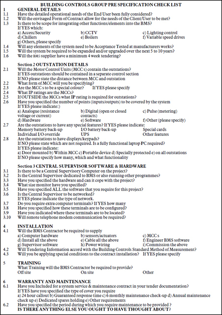
Figure 8.2 Pre-specification checklist (courtesy Building Controls Group)
— Part 2. Selection schedules. This part contains a list of references to the relevant Y Group Reference Specifications that are relevant to this work section. As well as invoking the relevant specification, the schedule invokes required clauses from Group Y, deleting irrelevant options; additional text may be inserted as required.
— Part 3. Clauses specific to the system. This contains information specific to the work section. The NES contains a large number of clauses and Part 3 is constructed by deleting clauses and options that are not required.
The NES is designed to aid production of specifications by providing a standard logical structure, which is amenable to incorporation in computer programs. As far as BMSs are concerned, it is complementary to the material presented in the BSRIA documents(12) and indeed Work Section W62 of the NES makes frequent reference to the BSRIA publication.
8.2.4 Conditions and tolerances
The specification of the required controlled conditions and permissible tolerances must be considered carefully. Setting unrealistically tight tolerances may result in either an unnecessarily expensive design solution to meet them, or a system which fails to meet the specification, with the attendant risk of legislation.
General comfort criteria are covered in Section A1 of the CIBSE Guide(14) and by ASHRAE-ANSI Standard 55(15). The most important variable is the temperature in the occupied space. This may be specified in terms of air temperature, environmental temperature or one of a number of comfort indices. The adaptive model of thermal comfort(16) states that it is permissible to allow space temperatures to rise in summer, since the occupants learn to adapt and minimise discomfort. This has importance for the design of HVAC systems, since it may be possible to reduce or even eliminate the need for air conditioning. Where this principle is adopted, the acceptable limits of building performance must be understood and accepted by all parties.
Where full air conditioning is employed, the required range of air temperature and humidity is specified. The interaction of air temperature, relative humidity and moisture content must be remembered. In general, the moisture content of the air in a building is less subject to variation than the air temperature. Changes in air temperature at constant moisture content may cause the relative humidity to go outside the specified range. People are not very sensitive to the level of ambient humidity and a range of 40 to 70% RH is normally found acceptable. If closer control is required, then the tolerances must be specified in such a manner that they can be realistically met by the HVAC system. Where central control of humidity is used, it may be better to specify humidity in terms of moisture content rather than relative humidity.
Similar considerations apply to plant operation. Control limits must be within the capability of the plant and its measurement and control system. When specifying the tolerances for system variables there is no point in specifying unnecessarily narrow limits, even if they can be met. The heat output from a heat emitter may be little affected by a 20% variation in water flow; however, a narrower specification is required for chilled water systems(17).
8.3 Tendering process
8.3.1 Pre-tendering
In many cases it is advantageous to draw up a short list of potential suppliers who will be asked to tender for the project. The use of a pre-tender brief allows selection of suitable tenderers to be produced, avoiding wasted effort. A pre-tender brief is given to possible suppliers, who are asked to return a questionnaire and are then interviewed to discuss the project in outline. The pre-tender brief contains enough information to indicate the size and complexity of the project, the available budget and the proposed time scale. The brief should contain the following:
— objective of the brief
— project description
— an indication of cost
— project management and form of contract
— building and plant schedules
— questionnaire.
8.3.2 Tendering
The usual documents required for the tendering process are shown in Table 8.3. More detail, together with examples of tender documentation, is given in BSRIA(12). If the pre-tendering process has produced a suitable short list and the specification has been properly drawn up, assessment of the tenders should be straightforward. To protect subcontractors against possible bad practices, a Code of Practice for the Selection of Subcontractors(18) has been published by the Construction Industry Board.
| Document | Purpose |
| Instructions to tenderers | How to complete the tender documents |
| Form of tender | On which the tender bid is returned |
| Tender details and summary | Cost breakdown of the tender price. Will provide the basis for any negotiation of variations |
| Form of contract and special conditions | |
| Full specification | Full set of standard and particular specifications, together with relevant plans and drawings |
| Information required from tenderer | Additional requirements needed to confirm details of the tender |
8.4 Commissioning
Commissioning is defined by CIBSE as ‘the advancement of an installation from static completion to working order to specified requirements (as envisaged by the designer)’. Correct commissioning is vital to the satisfactory operation of the HVAC system and it is essential that sufficient time and resources be allocated to the task. Since commissioning is the last major operation in the building process and the control system is the last system to be commissioned, there is every danger that commissioning the control system will take place under great time pressure or even continue after the building is occupied. Experience has shown only too well that this can create many problems, with an unacceptably high proportion of buildings failing to operate properly, with consequences of high energy consumption and occupant dissatisfaction. This section emphasises the importance of ensuring that commissioning takes its proper place in the procurement process from the start of planning the project.
Commissioning of the control systems is dependent on satisfactory operation of the electrical and mechanical services. The control system may also interact with specialist services such as security, access control and the IT system. The greater the degree of integration, the more planning is necessary and the more care required to define areas of responsibility(19). Sequential records of all stages of pre-commissioning and commissioning of all other aspects of the building must be issued prior to commencement of the commissioning of the automatic control system.
Table 8.4 summarises the stages of the procurement process and the activities which are relevant to the commissioning of the controls system.
Table 8.4 Commissioning activities during the procurement process
| Stage | Commissioning activity |
| Brief | Commissioning objectives |
| Appoint commissioning manager | |
| Design | Minimise need for commissioning |
| Design for commissionability | |
| Installation | Pre-commissioning |
| Commissioning | |
| Handover | Witnessing |
| O&M documentation | |
| User training | |
| Operation | Monitoring and feedback |
| System proving | |
| Fine tuning | |
| Recommissioning |
8.4.1 Commissioning management
For the traditional UK procurement organisation, the responsibilities for commissioning the BMS are shown in Table 8.5. This arrangement has the advantage of clearly defined responsibilities. However, it does not necessarily produce the most effective commissioning. The controls specialist, who is responsible for installation and commissioning, has little or no input into the design of the BMS, nor the design and commissioning of the plant which will be controlled by the BMS.
Table 8.5 Commissioning responsibilities for traditional procurement
| Party | Responsibility |
| Client | Write design brief |
| Appoint design consultant | |
| Design consultant | Write BMS functional specification |
| Review tenders from BMS contractors | |
| Appoint BMS contractor | |
| Witness commissioning | |
| Approve completion | |
| BMS contractor | Prepare tender |
| Design BMS to meet specification | |
| Install BMS | |
| Commission BMS |
8.4.1.1 Project management
The organisation and management of commissioning is described in detail by Pike and Pennycook(20), which gives examples of matrices of responsibilities for commissioning. Good project management is essential for large and complex projects and the subject is covered in the Guide to the BEMS Centre Standard Specification(12).
— A detailed commissioning programme should be written and agreed with the main contractor.
— There must be a means of monitoring progress.
— Checklists should be used to monitor progress.
— The controls specialist must have a documentation system in place for dealing with variations to contract.
Project management guidance(21) and BSRIA's Commissioning Guides define responsibilities for the personnel involved in the commissioning process. Duties will vary between projects depending on assigned responsibility. Example roles are detailed below.
The project manager has a coordinating, monitoring and controlling role for the project. The responsibilities include the following:
— aiding the client selecting the design team and other appropriate consultants and negotiating their terms and conditions of employment
— setting up the management and administrative structure for the project.
The client's commissioning manager provides the control point for commissioning for the client. The manager will be responsible for:
— arranging the appointment of the commissioning team
— establishing the commissioning objectives
— developing a comprehensive commissioning programme and preparing the roles and job descriptions for each member of the team
— arranging the sessions for user training at the end of the project.
The professional consultants must identify the services to be commissioned and define the responsibilities split between the contractor, manufacturer and client. They are also responsible for inspecting the work for which they have design responsibility (including inspecting the work at the end of the contract defects liability period) and defining the performance testing criteria to be adopted.
The site commissioning manager may be a member of the main contractor's team and provides the focus for the management of all the commissioning activities. The tasks may include the following:
— coordinating the professional team members and the client's involvement in commissioning
— ensuring that the contractors’ programmes include commissioning activities and that these coordinate with the main construction activity
— acquiring appropriate information from the relevant parties to ensure that the systems can be commissioned in accordance with relevant codes of practice
— witnessing works and site testing of plant, cleaning and commissioning
— demonstrating safety systems to the local authority, fire officer, district surveyor and the building insurer
— providing a focus to collect all handover documentation.
8.4.2 The brief
The original brief will lay down the foundation for the organisation of commissioning. This is the stage at which the organisation of the whole building procurement process is decided. For large projects, the appointment of a commissioning manager should be considered, with the responsibility of ensuring that the requirements of commissioning are considered at all stages. The manager will be responsible for appointing the commissioning team and ensuring that adequate resources for commissioning are built into the specification. Decisions should be taken at this stage whether commissioning should extend beyond the handover of the building and whether provision is to be made for system proving and post occupancy feedback when the building is in operation.
8.4.3 The design stage
Commissioning should be borne in mind at the initial design stage; this applies to both the HVAC system and the control system itself. Two complementary approaches are relevant:
— designing to minimise commissioning
— designing to make commissioning easier.
The amount of commissioning needed can be reduced by appropriate design:
— Design for self-balancing wherever possible.
— Balance pressure drops across sub-branches and terminal units.
— Avoid using different terminal units on same branch.
— Use reverse return pipework layouts.
— Use automatic balancing valves.
— Use variable-speed drives for fan and pump regulation.
— Use computer analysis to give settings for preset valves.
Attention to the needs of commissioning at the design stage will make it easier. Conversely, failing to provide the necessary facilities for commissioning may make it impossible. The following items will assist commissioning:
— Include regulating valves where appropriate.
— Include isolation valves and test points.
— Include flow measurement devices at main branches and major heat exchangers.
— Ensure that the system may be cleaned and vented.
— Ensure access for commissioning and maintenance(22).
— Provide items of plant with a ‘manual–off–auto’ switch. The switch can be set to ‘manual’ for commissioning the plant itself, prior to commissioning the BMS.
— Agree at an early stage a common procedure for allocating mnemonics to identify points uniquely.
— Obtain mid and full load design values from consultant.
The design consultants are responsible for writing the system specification, which includes the commissioning specification. At this stage a commissioning specialist should review the specification.
8.4.4 Installation
Satisfactory commissioning of the BMS is of course dependent on the correct installation and commissioning of the HVAC plant. The commissioning manager will ensure that plant is in a suitable condition before commissioning of the BMS commences and is certified as such. Above all, all water systems must be flushed clean; the presence of debris in water systems is a common cause of problems in the commissioning of valves.
8.4.4.1 Pre-commissioning the BMS
Pre-commissioning is the checking of all the components of the controls system, both on the bench and on site, before putting the system into operation for commissioning proper. As much checking should be done off site before installation; this will normally be faster and allow rapid rectification of any problems that are found. Checking of sensors for accuracy is best done off site under controlled conditions. The on-site pre-commissioning consists in checking that all items have been installed in the right place, the right way round and are wired correctly. Pre-commissioning tasks include:
— maximisation of off-site testing and pre-commissioning of control panels, application software etc.
— the checking of all wiring for short circuits, continuity, identification and termination
— the checking of all sensors for correct installation
— proving of all actuators
— proving the presence of outputs and devices on the network bus system.
8.4.4.2 Commissioning the BMS
Before commissioning can start, all control hardware must be installed and pre-commissioned. Any unitary controls on plant which is to be connected to the BMS should have been commissioned, or be commissioned in parallel with the BMS. The HVAC plant itself must have been commissioned; all plant items under control of the BMS must have been commissioned and the system flushed clean and vented. All electro-mechanical safety interlocks and fail safe conditions should be implemented and operational.
Commissioning the BMS consists of two major activities:
— checking that the control system works
— setting all parameters and switches to appropriate values, including tuning control loops.
Checking the system
Both the head end supervisor and the controls of particular building services plants have to be commissioned. The supervisor requires commissioning after installation. It may be commissioned in parallel with the outstations which control specific items of plant, when it can itself be used as an aid to commissioning. Full commissioning of the central supervisor requires previous completion of plant commissioning. For specific plant commissioning, the Code of Practice(20) sets out five basic items, to which has been added the relation with the supervisor:
— panel controls
— hardware points
— interlocks
— control loops
— alarms
— supervisor.
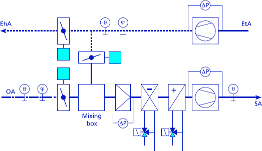
Figure 8.3 Air handling system to be commissioned
This procedure is illustrated by the example of an air handling unit shown in Figure 8.3. Table 8.6 summarises the tasks of the commissioning process; the example is summarised from Pike and Pennycook(20).
Setting the values
An important function of a BMS is its operation as a timeswitch, controlling the start and stop operation of many systems throughout the building, including optimisers. All BMS supervisors allow time schedules to be readily altered at the head end. However, experience shows that the initial settings may remain unaltered. Accordingly, the client should supply as much information as possible on required time and temperature schedules, to allow the correct values to be input during commissioning. It is recommended that the controls specialist sends a questionnaire to the client asking for relevant information. A sample questionnaire is given in the commissioning Code of Practice(20).
All control loops require to be tuned. While the goal is minimum response time consistent with stability, it must be remembered that the operating gain of a control loop is likely to vary with operating conditions, so that the gain will vary with season. Where possible, the loop should be tuned under conditions of maximum gain; this will ensure stability under all conditions. Various ways of tuning loops including the use of automatic tuning are discussed in 2.4.1.
Table 8.6 Commissioning an air handling unit
| Step | Function | Check |
| Panel controls | Power | Phases healthy, panel live, BMS power on |
| Fire alarm | Reset button, lamp test | |
| Supply fan | Run, trip, test/off/auto switch, overload range and set | |
| Extract fan | Run, trip, test/off/auto switch, overload range and set | |
| Fuses | Correct size, spares in panel | |
| Hardware points | Sensors | Outputs, correct connections |
| (at pre-commissioning) | Actuators | Full stroke travel |
| Connections | Continuity and polarity | |
| Interlocks | Fans | Supply and extract fan interlock |
| Dampers | Supply, extract and recirculation dampers synchronised | |
| Coils | Heater and cooler batteries move to default position on shut-down | |
| Fire | Appropriate action on fire signal, e.g. close supply and recirculation dampers, open exhaust damper, stop fans | |
| Control loops | Optimiser | Set parameters |
| Frost | Set and test frost protection and morning boost | |
| Control loop | Set proportional and integral constants | |
| Operation of valves and dampers | ||
| Enthalpy control if fitted | ||
| Run-time totalisation | ||
| Software | Check application software | |
| Timeswitches | Run through time schedules | |
| Alarms | General | Operation, labelling |
| Filter block | Set pressure switch and check operation | |
| Supply fan | Set pressure switch and inhibit time. Check operation | |
| Extract fan | Set pressure switch and inhibit time. Check operation | |
| Supervisor | Graphics | Points labelling, plant depiction |
| Control functions, correct values |
8.4.5 Handover
Once commissioning of the control system has been completed, it is demonstrated in front of witnesses and a completion certificate issued; the client's representative may attend. The witnessing officer will require a completion method statement which details the arrangements, methods and a list of items to be demonstrated in front of witnesses. Witnessing is just one part of completion. Documentation and training arrangements are also required. Table 8.7 summarises the items to be covered during completion. When all items have been completed to the satisfaction of the testers and witnesses, a certificate to that effect is signed off by both parties and handover takes place. Handover represents change of ownership from contractor to client.
8.4.5.1 Witnessing
The organisation of witnessing will depend on the nature of the system and is decided by the witnessing officer. For large projects, there are advantages in a phased approach, so that witnessing of completed subsystems can begin before final completion of the whole system. It is not essential that every point be checked. A sufficient number should be checked to give the witnesses confidence in the overall reliability, using a quality control approach. The method suggested in the BEMS commissioning Code of Practice(20) is:
Table 8.7 Completion checklist(20)
| Item | Description |
| 1 | Audit of cabling and hardware installation |
| 2 | Demonstration that sensors and actuators are correctly connected and addressed |
| 3 | Demonstration of the physical and logical integrity of the system |
| 4 | Demonstration of the sensor calibrations |
| 5 | Demonstration of all control actions |
| 6 | Demonstration of successful system software commissioning. (This should include loading and subsequent operation) |
| 7 | Verification of specified graphics |
| 8 | Verification of specified training arrangements |
| 9 | Verification of handover of all specified manuals, documentation and drawings |
| 10 | Verification of handover of back-up copies of software |
| 11 | Verification of handover of consumable spares |
— The BMS controlling the main plant (e.g. boilers and chillers) and other important points should be witnessed completely.
— The proportion of other points to be witnessed depends on the size of the system, e.g. if fewer than 300 points, witness all the points, between 300 and 1000 points, witness 50%, and if more than 1000 points, witness 20%.
— If the failure rate is greater than 15%, the supervising officer should have the right to witness 100% of the points.
— Where there are several similar plants, one can be witnessed in detail and the others on a sampling basis.
8.4.5.2 Documentation
Good operations and maintenance (O&M) documentation is necessary for successful:
— day-to-day operation of the system
— effective maintenance
— system refurbishment.
There is a statutory requirement under the CDM Regulations(23,24) to provide proper documentation. The client is required to appoint a planning supervisor, whose function is to ensure that a health and safety plan is prepared, to advise the client on the necessary resources required to implement the plan, and to prepare the health and safety file. The health and safety file is a record of information for the end user, which tells those who might be responsible for the building in the future of the risks that have to be managed during maintenance, repair or renovation. Operation, maintenance and commissioning documentation make up part of the health and safety file. The file must include details of hazards and risks, and the safety certificates collected during construction. The documentation must be presented in the format required by the regulations(25).
While all building services require proper O&M documentation, the complex nature of a BMS, which may have control strategies and other information stored in computer memories, makes it essential to provide written details of what function the BMS performs and how it achieves them. Advice on the preparation of O&M manuals is given in Armstrong(26). The documentation should include:
— written description of plant operation
— control strategy or logic diagrams recording the final version of installed software
— details of system application software configuration
— points list, including hard and soft points
— copies of certificate of compliance with relevant standards
— data sheets for all control components and equipment
— instructions for switching on, operation and switching off, isolation, fault finding and for dealing with emergency conditions
— instructions for any necessary precautionary measures
— instructions for servicing
— instructions in the use of software routines for creating procedures, graphics reports etc., where applicable
— description of user adjustable points
— provision for updates and modifications.
The file may be in two parts: operating manuals for day-today use and sets of drawings for use during alterations. Copies of manufacturers’ data may be incorporated, but are not a substitute for proper instructions. Details of spares and sources of supply should be included. In addition, there should be a complete set of record documents supplied at handover, containing records of all the commissioning values and the checklists completed during commissioning and witnessing.
8.4.5.3 Training
The successful operation of a BMS depends on the skill and knowledge of the operator. The installation of a modern BMS represents a substantial investment and proper operator training is necessary to realise the full value of this investment. The client has to decide who will operate the BMS. In many cases this will be staff, but the contracting out of facilities management services is becoming more common. Training is often part of the contract and so contract completion is not possible until the training has been carried out. This may result in financial pressure to perform the training too early, before the end user is ready or staff have been appointed. It is recommended that training costs should be determined and held as a PC sum outside the main contract, to be paid when the training is completed.
It is recommended that:
— at least two BMS operators attend an ‘in-house’ training course run by the controls specialist before completion of the BMS
— the BMS operators are invited to attend the commissioning of the BMS
— the BMS operators should be present during the handover period to learn about the system
— all new operators who may subsequently be appointed should also receive proper training.
8.4.6 Costing
The importance of commissioning to the satisfactory operation of the plant and control system has been emphasised. It therefore requires proper provision of time and cost to enable the process to be carried out satisfactorily; allowing commissioning to absorb time and cost overruns is not satisfactory. Effective commissioning has long lasting benefits, which need to be given full value when making out a business case for expenditure; inadequate commissioning is sure to prove expensive over the long run. The benefits of effective commissioning may be summarised:
— increased building value
— improved occupant satisfaction and productivity
— reduced energy costs
— reduced maintenance requirements and longer plant life
— sound database for future refurbishment.
When costing proposals, all activities should be taken into account, including provision for post-occupancy evaluation and fine tuning.
8.5 Operation
8.5.1 Fine tuning
After handover, the building operates under control of the appropriate staff, whether in-house staff, a contract facilities management team or other form of organisation. It is rare that a new building works perfectly without further attention; it would be unreasonable to expect this, since the manner of building use by the occupants cannot always be predicted and it will not have been possible during commissioning to experience the full range of weather conditions. It is therefore to be expected that the BMS will require attention and tuning over a period of at least a year after occupation. Proper provision should be made for this, in terms of effort and cost. This should include an allowance for a return visit at least twice during the first year. In most cases, it will be of great benefit for all concerned if the client installs a dedicated telephone line to allow remote monitoring of the BMS by the controls specialist. As well as assisting in fault diagnosis, the link can be used for training and other purposes.
8.5.2 Maintenance
While the microelectronics components in a BMS are in general very reliable, a controls systems contains moving parts which are subject to wear and devices such as sensors which may be subject to physical damage or degradation from their environment. Maintenance is therefore essential to ensure that a BMS stays in efficient working order throughout its life. Maintenance includes updating and maintenance of software and documentation.
Maintenance may be obtained from different types of provider:
— In-house staff. Only large organisations with a sophisticated building are likely to carry the necessary technical staff to provide BMS maintenance. In-house staff may be used to provide the first line of investigation into failures and carry out simple repairs, calling on specialist contractors for more complex work.
— Maintenance divisions of M&E companies. Many M&E contractors operate specialist maintenance divisions that will undertake maintenance of BMS systems, whether installed by the parent company or not. The maintenance companies are generally autonomous companies, so it should not be assumed that there is a continuity of responsibility between installer and maintenance company.
— Systems integrators. Many of the larger systems integrators provide comprehensive maintenance and 24 hour bureau services. This may include remote monitoring of plant condition.
— Specialised maintenance companies. There is a large number of small specialised maintenance companies, often specialising in a particular range of equipment. Although not having the resources of the large M&E companies, they can supply a service tailored to the customer's needs.
— Consultants. An increasing number of engineering consultants offer maintenance services, including training or documentation production, and the management of maintenance on behalf of the building operator.
— Controls manufacturers. Several major manufacturers offer maintenance contracts of systems using their equipment.
Whichever method is chosen, it is important that the maintenance is specified carefully(9). As a minimum, a maintenance specification should include requirements for:
— software upgrades
— data back-up and archiving
— checking of sensors and actuators
— arrangements for emergency callout
— performance standard for the building control system, including delivered conditions and operating efficiency.
As with commissioning, it is advantageous if the needs of maintenance are considered at an early stage; the several approaches to the organisation of maintenance are reviewed in Smith(27) and CIBSE TM17(28). Plant and equipment should be designed and installed in a manner to assist future maintenance; recommendations are given by MoD(22) and Parsloe(29). Advice on specification and contracts is to be found in Smith(30) and Standard Maintenance Specification(31). Experience shows that the best results are obtained in situations where the BMS is ‘owned’ by someone in the building operator's organisation. There should be an individual who feels responsible for the proper operation of the BMS and will take whatever initiative is necessary to ensure its successful working.
8.5.3 Recommissioning
Existing buildings may operate below optimum performance and recommissioning the building services may represent the most effective way to bring operation up to the required standard. Recommissioning can often be justified by:
— evidence of occupant dissatisfaction
— high operating costs or energy consumption
— high maintenance costs
— a change in building use
— major plant overhaul or replacement
— repeated system failures.
8.6 Occupant surveys
The experience of the building occupants plays an important part in the evaluation of the performance of a building control system. Building users consistently place good environmental control at the top of the list of desirable features in a workplace. A well-controlled environment not only produces comfort, but contributes to productivity and health as well as influencing the occupants’ general opinion of other facilities. The series of PROBE post-occupancy studies of buildings has emphasised the importance of a well-controlled environment and emphasised that the occupants themselves are part of the system. Disregarding the responses of the users will itself create problems, even if the mechanical system is performing adequately. The published summary of the first PROBE series produced a set of key design lessons about the requirements of the occupant(32).
— Rapid response to changes. There should be a rapid response to the need for a change, whether this is provided automatically by the BMS or by management intervention.
— Offer choices and trade-offs. If ideal conditions cannot be provided, the occupants should be offered a choice of trade-offs, e.g. in hot conditions, openable windows allow a choice between being hot or suffering from external noise.
— Good feedback mechanisms. These are essential so that action can be taken quickly. Complaints or problems need to receive rapid attention. The trend towards contracting out services such as facilities management can work against rapid response.
— Management resources. These are vital; complicated buildings can outstrip the limited capabilities of the occupiers to run them effectively.
— Ownership of some problems by the occupants. This is so that they may participate in the solution without suffering a sense of alienation.
— Perception of good control. This is important to occupants, who require simple effective controls or else rapid and effective management response to requests.
The above design lessons emphasise that the users must perceive that they are part of the control system. However good the control system may be in technical terms, if the manner in which it is operated ignores the feelings and responses of the building occupants, then it will not be found satisfactory. The application of the above lessons will result in working methods whereby early indications of unsatisfactory operation of the building control system come to the attention of the building operator. Other indications may come from the energy monitoring and targeting procedures. In any case, it may be advantageous to initiate a regular review of system performance, say one year after installation and at longer intervals thereafter. When it is desired to initiate a proactive review of the operation of the building services operation, BRECSU propose a three-level strategy to review building performance, which can be initiated at any stage of the building's life.
— Level 1. Review performance, using a help desk or focus groups to obtain the views of occupants. Assess energy performance against targets or benchmarks and ensure that health and safety requirements are met. If there is cause for concern, move on to Level 2.
— Level 2. Use a more formal procedure to identify any problems. Use occupation satisfaction surveys and energy surveys. If performance problems are established, go to Level 3.
— Level 3. Employ plant-focused troubleshooting procedures to find the cause of troubles. Systems can then be fine tuned, recommissioned or refurbished as required.
The relation between building controls and complaints of poor indoor environmental quality is set out by Fletcher(33). Reports of poor conditions are classified into 16 divisions and an action checklist for each is given. The suggested actions only apply if the problem is controls related or can be mitigated by modifying the control set-up.
A detailed occupant satisfaction survey demands a formal approach. The use of a standardised questionnaire will provide a satisfaction score for the building that will enable its performance to be compared with national benchmarks, as well as identifying areas of control and management that require attention. The PROBE standard questionnaire is copyright and may be used under licence; this ensures that it is applied according to standard procedures. Formal occupant surveys should be undertaken with caution, both to ensure results that can be compared with benchmarks and to avoid possible staff-related problems.
— The questionnaire should be short and easy to answer in at most 10 minutes.
— In large buildings, a representative sample of occupants should be surveyed, aiming at as high a response rate as possible.
— The provisions of the Data Protection Act must be borne in mind.
— The staff association or other relevant body should be kept fully informed.
— Make the goal of the survey clear to respondents; do not raise unrealistic expectations of improvement in conditions.
— Resolve any questions of confidentiality in advance.
— If the survey is to be conducted by external researchers, resolve questions of ownership of data and possible publication in advance.
One type of questionnaire provides a visual fingerprint of occupants’ response to their working environment as well as an overall building score. Respondents are asked to rate up to 24 factors on a double Likert scale. This asks for two responses for each factor. One is a seven-point scale running from ‘like’ to ‘dislike’; the other is a seven-point scale describing how important that factor is. The factors cover physical aspects of the indoor environment such as temperature and humidity, but also include some organisational factors. The responses from all respondents may be combined to give an overall liking score (OLS) for the building. The use of the importance scale means that appropriate weighting is given to each factor when computing the OLS. The overall liking score is expressed as a percentage, running from +100% to –100%. The questionnaire has been evaluated in several surveys and has been found to differentiate well between buildings(34). In practice, OLS scores range from about +20% for a well-liked building, down to –20% or worse for one disliked by its occupants. Total scores for the individual factors may be displayed as a bar chart, termed the building fingerprint; an example is shown in Figure 8.4. This gives an immediate picture of the good and bad features of the building and can be a useful tool in ascertaining which aspects of a building require attention during a post-occupancy survey.
8.7 Cost issues
8.7.1 Cost benefit analysis
A comprehensive BMS represents a substantial investment, which is expected to bring a variety of benefits to the client. In order to make a rational investment decision, it is necessary to have some method of comparison between alternative systems. Cost benefit methods of analysis have been developed by economists, which aim to express all costs and benefits associated with a plan of action in a common unit, i.e. money, and to make rational comparisons between plans which may have different size and time scales. One important principle is that the benefits and costs must be expressed from a single point of view, e.g. better indoor air quality may be beneficial to the office worker in terms of health and comfort and it may produce a benefit for the office tenant in terms of increased productivity. However, neither is a direct benefit for the building owner, who may be able to achieve the benefit as an increased rent. Cost benefit analysis is most straightforward where the building owner, operator and employer are the same. Where they are not, it must be borne in mind that the organisation receiving the benefit, e.g. of a reduction in energy consumption, may not be the organisation that paid for the BMS.
The IEA Annex 16 task, Cost Benefit Assessment Methods for BEMS(35) set out to produce a coherent analysis procedure which could be used to calculate savings from BMS and assist in making investment decisions. The report concluded that no single model would become accepted; the more common methods of analysis are given in the report and summarised below. More important than the method chosen is the ability to provide good quality input data, particularly where it is necessary to compare different types of costs and savings, e.g. investment cost versus productivity gain. It is recommended that a detailed listing is prepared of the costs incurred and the benefits expected from the BMS. Table 8.8 summarises the suggested headings, which may be expanded into considerably more detail.
In a modern office building, staffing costs are much greater than energy costs. The benefits of improved staff utilisation may therefore be as much or more than the savings in energy consumption. The IEA report quotes estimates which state that the benefits of an intelligent building in terms of energy savings, increased productivity and reduction in building management costs are roughly equal; put another way, this means that the overall benefits of a good BMS may be three times the direct saving in energy consumption. Another rule-of-thumb quoted is that an overall productivity improvement of 2.5% would be enough to pay for the entire BMS.
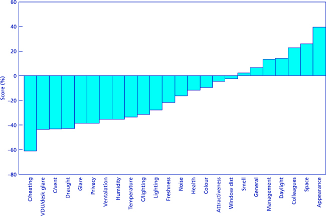
Figure 8.4 Fingerprint of a deep plan, modern, naturally ventilated building. (OLS –15%; C/ = control of)
Table 8.8 Listing of costs and benefits of a BMS
| First cost | Specification and design |
| Hardware | |
| Software | |
| Installation, commissioning | |
| Training | |
| On-going costs | Maintenance |
| Communication costs | |
| Staffing | |
| Benefits | Reduction in avoidable waste |
| Savings in staffing costs | |
| Better maintenance and fault detection | |
| Improved productivity | |
| Tax implications | |
| Life cycle factors | Replacement cost |
| Scrap value | |
| System economic life | |
| Life of related systems |
8.7.2 Life cycle costing
Life cycle costing is an emerging technique that seeks to extend the cost benefit analysis over the whole life of the project, including final disposal. It has been defined as a method that collects together all tax allowances, capital and revenue costs for each system from original installation to abandonment. As with all such analyses, the quality of the data is of vital importance. For life cycle costing to take place, the tender invitation should include separate price breakdowns as follows:
— installation cost
— annual maintenance cost of components
— cost and rate of increase of maintenance contracts
— cost of replacement items
— economic life of system and components
— minimum guaranteed period that spares will be available
— system training costs.
The relation between BMS lifetime and the lifetime of related systems may be important. IT systems in general have a shorter life than BMS. If the BMS is to be closely integrated with the IT system, there may be implications for the BMS if the IT system is renewed. Similarly, replacement cycles for the BMS should be related to the likely lifetime of the HVAC system.
8.7.3 Assessment methods
There are several assessment methods available which are to be found in standard economic texts, e.g. Thuesen et al.(36) and ETSU(37). It is emphasised again that good quality data is important, and that the costs and benefits should be assessed from the same standpoint. The main methods are summarised as follows.
8.7.3.1 Net cash flow
Cash flow analysis is the basis for all cost benefit analyses. For a number of periods, typically yearly, the costs and benefits of the investment opportunity are written down. The total period may extend up to the expected life of the investment, including disposal costs for full life cycle costing. Thus the cash flow table shows both the total costs and benefits and when they are expected to be achieved.
8.7.3.2 Payback method
The payback period is commonly defined as the length of time to recover the initial investment from the benefits produced by that investment; no account is taken of interest rates. Using the cash flow table described above, the net cash flow is accumulated. The year in which the total benefits equal the total cost is the simple payback period, i.e. it is the time after which the investment cost is repaid. There are several variants on the payback period and it is important to state which one is used when making comparisons. For instance, the payback period calculated by dividing the initial cost by the annual benefits does not take into account the initial period, e.g. construction phase, during which no benefits are received.
In general the payback period fails to consider the time value of money, i.e. the value of money to be received in the future is less than that of money received now, nor does it consider what happens after the payback period, e.g. the magnitude and timing of the cash flows. The payback method tends to favour shorter lived investments. Acceptable values of payback period vary with the type of organisation. Typically, payback period of three years or less are required by industry and up to 10 years by Government projects.
8.7.3.3 Discount techniques
There are several techniques based on discounted cash flow (DCF), all of which use a discount rate in the calculations, reflecting the time value of money(38,39). The present worth method, also known as net present value, is typical. All future amounts in the cash flow table are discounted back to the start of the project. The discount rate may be thought of as the return available on money from other investments; 10% is typically used. With this method of analysis, it is possible that an investment which shows a positive net cash flow after a few years may show a negative present worth; the implication is that it would be more profitable to invest the money elsewhere. The techniques can be used for life cycle costing; the effect of the discount rate is to reduce the present value of costs and benefits which will occur more than a few years in the future.
8.8 Summary
The procurement process chosen by the client strongly influences the way in which the control system is designed and installed. The traditional procurement process separates design from construction. This provides for clear contractual responsibilities, but means that the controls specialist may be appointed late in the process and have little opportunity to contribute to the design. Design and build brings design and construction together in the same organisation. Partnering methods aim to build a stable relationship between those involved in the procurement process, enabling all parties involved to make a full contribution.
The initial project brief produced by the client is of great importance and the type of control system and the organisation of commissioning should be considered from the start. The manual includes a pre-specification check list to assist in clarifying ideas about the required building management system.
It is helpful if the specification follows a standard form, such as the National Engineering Specification. Once the HVAC and control system has been installed, effective commissioning is crucial. In modern complex buildings, the controls system interacts with other systems and care is necessary in planning the commissioning process and assigning areas of responsibility. The original specification should be designed both to reduce the amount of commissioning required and to make that commissioning easier. The design should be reviewed at an early stage by a commissioning specialist.
There are statutory requirements for the preparation of proper documentation, which is necessary for system operation, maintenance and refurbishment.
After the building is occupied, it must be run to provide a satisfactory working environment for its occupants. Prompt response to any user problems is important in producing satisfaction. Where there appear to be problems a survey of the building users can be helpful; standard questionnaires can be used to provide comparison with other buildings.
Decisions on how much to spend on control systems should involve the concept of life cycle costing, taking future running costs, maintenance expenditure and energy saving into account. Standard discounted cash flow techniques can be used to evaluate proposals.
References
1 Thinking about building (Business Round Table) (1995)
2 Turner A E Building procurement 2nd ed (London: MacMillan) (1997)
3 Latham M Constructing the team. Final report of the Government/industry review of procurement and contractual arrangements in the UK construction industry (London: Stationery Office) (1994)
4 Hawkins G Improving M&E site productivity TN 14/97 (Bracknell: Building Services Research and Information Association) (1997)
5 Egan J Rethinking construction (London: Department of Environment, Transport and Regions) (1998)
6 RCF Trusting the team — the best practice guide to partnering in construction (University of Reading: Centre for Strategic Studies in Construction) (1995)
7 Anderson D Partnering: all together now Journal of the Chartered Institution of Building Services 17(11) 31–34 (1995)
8 Parsloe CJ Allocation of design responsibility TN21/97 (Bracknell: Building Services Research and Information Association) (1997)
9 Pennycook K and Hamilton G Specifying building management systems BSRIA TN 6/98 (Bracknell: Building Services Research and Information Association) (1998)
10 Teekeram A J H and Grey R W Specifications and standards for BEMS (St Albans: Oscar Faber) (1991)
11 NES National engineering specification (London: Building Services Research and Information Association) (1997)
12 BSRIA Guide to BEMS Centre Standard Specification AH1/90 Vol 1 (Bracknell: Building Services Research and Information Association) (1990)
13 PSA Building management systems, Standard Specification (M&E) No 15 (London: Property Services Agency) (1986)
14 Environmental Design CIBSE Guide A (London: Chartered Institution of Building Services Engineers) (1999)
15 Thermal environmental conditions for human occupancy ANSI/ASHRAE Standard 55 (Atlanta, GA: American Society of Heating, Refrigeration and Air Conditioning Engineers) (1992)
16 Nicol F, Humphreys M A, Sykes O and Roaf S Indoor air temperature standards for the 21st century (London: E & F N Spon) (1995)
17 Parsloe C J and Spencer A W Design and commissioning of pipework systems TN 20/95 (Bracknell: Building Services Research and Information Association) (1995)
18 Sneath C Code of practice for the selection of subcontractors (London: Thomas Telford Publishing) (1997)
19 Wild L J Commissioning HVAC systems. Division of responsibilities AG 3/89 (Bracknell: Building Services Research and Information Association) (1989)
20 Pike P G and Pennycook K Commissioning BEMS — a code of practice AH 2/92 (Bracknell: Building Services Research and Information Association) (1992)
21 Chartered Institution of Building Code of practice for project management for construction and development (Chase Production Services) (1992)
22 MoD Space requirements for plant access, operation and maintenance. Defence Works Functional Standard: Design and Maintenenance Guide 08 (London: Stationery Office) (1996)
23 The Construction (Design and Management) Regulations 1994 (London: Stationery Office) (1994)
24 Managing construction for health and safety. Construction (Design and Management) Regulations 1994 Approved Code of Practice (L54) (Sudbury, Suffolk: HSE Books) (1995)
25 Nanayakkara R Standard specification for the CDM Regulations Health and Safety File AG 9/97 (1997)
26 Armstrong J H Operation and maintenance manuals for building services installations. Application Guide 1/87.1 2nd ed (Bracknell: Building Services Research and Information Association) (1990)
27 Smith M H Decisions in maintenance TN 14/92 (Bracknell: Building Services Research and Information Association) (1992)
28 Maintenance management for building services TM 17 (London: Chartered Institution of Building Services Engineers) (1994)
29 Parsloe C J Design for maintainability AG 11/92 (Bracknell: Building Services Research and Information Association) (1992)
30 Smith M H Maintenance contracts for building engineering services. A guide to management and documentation AG 4/89.1 (Bracknell: Building Services Research and Information Association) (1991)
31 Standard maintenance specification for mechanical services in buildings. Volume 3: Control, energy and BMS (London: Heating and Ventilating Contractors Association) (1992)
32 Leaman A PROBE 10 occupancy survey analysis Building Services Journal 19(5) 37–41 (1997)
33 Fletcher J Building control and indoor environmental quality — a best practice guide (Bracknell: Building Services Research and Information Association) (1998)
34 Leventis M and Levermore G J Occupant feedback — important factors for occupants in office design Chartered Institution of Building Services Engineers/ASHRAE Joint National Conference Part Two Harrogate UK 1996 II. 192–200 (London. Chartered Institution of Building Services Engineers) (1996)
35 Hyvärinen J Cost benefit assessment methods for BEMS (St Albans: Oscar Faber) (1992)
36 Thuesen H G, Fabrycky W J and Thuesen G J Engineering economy 5th ed (New Jersey: Prentice Hall) (1977)
37 ETSU Economic evaluation of energy efficiency projects (Harwell: ETSU) (1994)
38 Wright M G Using discounted cash flow in investment appraisal 3rd ed McGraw-Hill) (1990)
39 Dixon R Investment appraisal. A guide for managers Revised ed (Kogan Page) (1994)