CHAPTER 5
IT Service Management and Continuity
This chapter covers CISA Domain 4, “Information Systems Operations and Business Resilience,” and discusses the following topics:
• Information systems operations
• Information systems hardware
• Information systems architecture and software
• Network infrastructure, technologies, models, and protocols
• Business continuity and disaster recovery planning
• Auditing infrastructure, operations, business continuity and disaster recovery planning
The topics in this chapter represent 23 percent of the CISA examination.
IT organizations are effective if their operations are effective. Management needs to be in control of information systems operations, which means that all aspects of operations need to be measured, those measurements and reports reviewed, and management-directed changes carried out to ensure continuous improvement.
IT organizations are service organizations—they exist to serve the organization and support its business processes. IT’s service management operations need to be well designed, adequately measured, and reviewed by management.
In the age of digital transformation (DX), organizations are more dependent than ever before on information technology for execution of core business processes. This, in turn, changes the business resilience conversation and increases the emphasis on business continuity and disaster recovery planning, which has moved to this domain in the 2019 CISA job practice.
In addition to being familiar with IT business processes, IS auditors need to have a keen understanding of the workings of computer hardware, operating systems, and network communications technology. This knowledge will help the auditor better understand many aspects of service management and operations.
Information Systems Operations
IS operations encompass the day-to-day control of the information systems, applications, and infrastructure that support organizational objectives and processes. IS operations is composed of several sets of activities, which include management and control of operations:
• IT service management
• IT operations and exception handling
• End-user computing
• Software program library management
• Quality assurance
• Security management
• Media control
• Data management
These activities are discussed in detail in the remainder of this section, following a brief overview describing how IS operations need to be managed and controlled.

NOTE Don’t get too hung up on the terms “IS operations” versus “IT operations”; often they are considered synonymous.
Management and Control of Operations
All of the activities that take place in an IT department should be managed and controlled. This means that all actions and activities performed by operations personnel should be a part of a control, procedure, process, or project that has been approved by management. Processes, procedures, and projects should have sufficient recordkeeping so that management can understand the statuses of these activities.
Management is ultimately responsible for all activities that take place in an IS operations department. The primary high-level management activities that govern IS operations are
• Development of processes and procedures Every repetitive activity performed by any operations personnel should be documented in the form of a process or procedure. This means that documents that describe each step of every process and procedure need to be developed, reviewed, approved by management, and made available to operations staff.
• Development of standards From the way that operations perform tasks to the brands and technologies used, standards drive consistency in everything that IS operations does.
• Resource allocation Management is responsible for allocating resources that support IS operations, including manpower, technology, and budget. Resource allocation should align with the organization’s mission, goals, and objectives.
• Process management All IS operations processes should be measured and managed. This will ensure that processes are being performed properly, accurately, and within time and budget targets.
IT Service Management
IT service management (ITSM) is the set of activities that ensures the delivery of IT services is efficient and effective, through active management and the continuous improvement of processes.
ITSM consists of several distinct activities:
• Service desk
• Incident management
• Problem management
• Change management
• Configuration management
• Release management
• Service-level management
• Financial management
• Capacity management
• Service continuity management
• Availability management
Each of these activities is described in detail in this section.
ITSM is formally defined in the IT Infrastructure Library (ITIL) process framework, a well-recognized standard. The content of ITIL is managed by AXELOS. ITSM processes can be audited and registered to the ISO/IEC 20000:2011 standard, the international standard for ITSM.
Service Desk
Often known as the helpdesk or call center, the IT service desk function handles incidents and service requests on behalf of internal IT customers by acting as a single point of contact. The service desk performs end-to-end management of incidents and service requests (at least from the perspective of the customer) and also is responsible for communicating status reports to the customer for matters that take more time to resolve.
The service desk can also serve as a collection point for other ITSM processes, such as change management, configuration management, service-level management, availability management, and other ITSM functions.
Incident Management
ITIL defines an incident as “an unplanned interruption to an IT service or reduction in the quality of an IT service. Failure of a configuration item that has not yet affected service is also an incident—for example, failure of one disk from a mirror set.”
Thus, an incident may be any of the following:
• Service outage
• Service slowdown
• Software bug
Regardless of the cause, incidents are a result of failures or errors in any component or layer in IT infrastructure.
In ITIL terminology, if the incident has been experienced before and its root cause is known, this is a known error. If the service desk is able to access the catalog of known errors, this may result in more rapid resolution of incidents, resulting in less downtime and inconvenience. The change management and configuration management processes are used to make modifications to the system in order to fix it temporarily or permanently.
If the root cause of the incident is not known, the incident may be escalated to a problem, which is discussed in the next section.
Problem Management
When several incidents have occurred that appear to have the same or a similar root cause, a problem is occurring. ITIL defines a problem as “a cause of one or more incidents.”
The overall objective of problem management is the reduction in the number and severity of incidents.
Problem management can also include some proactive measures, including system monitoring to measure system health and capacity management that will help management to forestall capacity-related incidents.
Examples of problems include
• A server that has exhausted available resources that result in similar, multiple errors (which, in ITSM terms, are known as incidents)
• A software bug in a service that is noticed by and affecting many users
• A chronically congested network that causes the communications between many IT components to fail
Similar to incidents, when the root cause of a problem has been identified, the change management and configuration management processes will be enacted to make temporary and permanent fixes.
Change Management
Change management is the set of processes that ensures all changes performed in an IT environment are controlled and performed consistently. ITIL defines change management as follows: “The goal of the change management process is to ensure that standardized methods and procedures are used for efficient and prompt handling of all changes, in order to minimize the impact of change-related incidents upon service quality, and consequently improve the day-to-day operations of the organization.”
The main purpose of change management is to ensure that all proposed changes to an IT environment are vetted for suitability and risk, and to ensure that changes will not interfere with each other or with other planned or unplanned activities. To be effective, each stakeholder should review all changes so that every perspective of each change is properly reviewed.
A typical change management process is a formal “waterfall” process that includes the following steps:
1. Proposal or request The person or group performing the change announces the proposed change. Typically, a change proposal contains a description of the change, the change procedure, the IT components that are expected to be affected by the change, a verification procedure to ensure that the change was applied properly, a back-out procedure in the event the change cannot be applied (or failed verification), and the results of tests that were performed in a test environment. The proposal should be distributed to all stakeholders several days prior to its review.
2. Review This is typically a meeting or discussion about the proposed change, where the personnel who will be performing the change can discuss the change and answer stakeholders’ questions. Since the change proposal was sent out earlier, each stakeholder should have had an opportunity to read about the proposed change in advance of the review. Stakeholders can discuss any aspect of the change during the review. The stakeholders may agree to approve the change, or they may request that it be deferred or that some aspect of the proposed change be altered.
3. Approval When a change has been formally approved in the review step, the person or group responsible for change management recordkeeping will record the approval, including the names of the individuals who consented to the change. If, however, a change has been deferred or denied, the person or group that proposed the change will need to make alterations to the proposed change so that it will be acceptable, or they can withdraw the change altogether.
4. Implementation The actual change is implemented per the procedure described in the change proposal. Here, the personnel identified as the change implementers perform the actual change to the IT system(s) identified in the approved change procedure.
5. Verification After the implementers have completed the change, they will perform the verification procedure to make sure that the change was implemented correctly and that it produces the desired result. Generally, the verification procedure will include one or more steps that include the gathering of evidence (and directions for confirming a correct versus an incorrect change) that shows the change is correct. This evidence will be filed with other records related to the change and may be useful in the future if there is any problem with the system where this change is suspected as a part of the root cause.
6. Post-change review Some or all changes in an IT organization will be reviewed after the change is implemented. In this activity, the personnel who made the change discuss the change with other stakeholders to learn more about the change and whether any updates or future changes may be needed.
These activities should be part of the duties of a change control board, a group of stakeholders from IT and every group that is affected by changes in IT applications and supporting infrastructure.
NOTE The change management process is similar to the system development life cycle (SDLC) in that it consists of life cycle activities that systematically enact changes to an IT environment.
Change Management Records Most or all of the activities related to a change should include updates to business records so that all of the facts related to each change are captured for future reference. In even the smallest IT organization, there are too many changes taking place over time to expect that anyone will be able to recall facts about each change later on. Records that are related to each change serve as a permanent record.
Emergency Changes Though most changes can be planned in advance using the change management process described here, there are times when IT systems need to be changed right away. Most change management processes include a process for emergency changes that details most of the steps in the nonemergency change management process, but they are performed in a different order. The steps for emergency changes are
• Emergency approval When an emergency situation arises, the staff members attending to the emergency should still seek management approval for the proposed change. This approval may be done by phone, in person, or in writing (typically, e-mail). If the approval was by phone or in person, e-mail or other follow-up communication is usually performed. Certain members of management should be designated in advance who can approve these emergency changes.
• Implementation Staff members perform the change.
• Verification Staff members verify that the change produced the expected result. This may involve other staff members from other departments or end users.
• Review The emergency change is formally reviewed. This review may be performed alongside nonemergency changes with the change control board, the same group of individuals who discuss nonemergency changes.
Like nonemergency changes, emergency changes should be fully documented with records made available for future reference.
Linkage to Problem and Incident Management Often, changes are made as a result of an incident or problem. Emergency and nonemergency changes should reference specific incidents or problems so that those incidents and problems may be properly closed once verification of their resolution has been completed.
Configuration Management
Configuration management (CM) is the process of recording the configuration of IT systems. Each configuration setting is known in ITSM parlance as a configuration item (CI). CIs usually include the following:
• Hardware complement This includes the hardware specifications of each system (such as CPU speed, amount of memory, firmware version, adaptors, and peripherals).
• Hardware configuration Settings at the hardware level may include boot settings, adaptor configuration, and firmware settings.
• Operating system version and configuration This includes versions, patches, and many operating system configuration items that have an impact on system performance and functionality.
• Software versions and configuration Software components such as database management systems, application servers, and integration interfaces often have many configuration settings of their own.
Organizations that have many IT systems may automate the CM function with tools that are used to record and change configuration settings automatically. These tools help to streamline IT operations and make it easier for IT systems to be more consistent with one another. The database of system configurations is called a configuration management database (CMDB).
Linkage to Problem and Incident Management An intelligent problem and incident management system is able to access the CMDB to help IT personnel determine whether incidents and problems are related to specific configurations. This can be a valuable aid to those who are seeking to determine a problem’s root cause.
Linkage to Change Management Many configuration management tools are able to detect system configuration changes automatically. With some change and configuration management systems, it is possible to correlate changes detected by a configuration management system with changes approved in the change management process. Further, many changes that are approved by the change management process can be performed by configuration management tools, which can be used to push changes out to managed systems.
Release Management
Release management is the ITIL term used to describe the portion of the SDLC where changes in applications and other information systems are placed into production and made available to end users. Release management is used to control the changes that are made to software programs, applications, and environments.
The release process is used for several types of changes to a system, including the following:
• Incidents and problem resolution Casually known as bug fixes, these types of changes are done in response to an incident or problem, where it has been determined that a change to application software is the appropriate remedy.
• Enhancements New functions in an application are created and implemented. These enhancements may have been requested by customers, or they may be a part of the long-range vision on the part of the designers of the software program.
• Subsystem patches and changes Changes in lower layers in an application environment may require a level of testing that is similar to what is used when changes are made to the application itself. Examples of changes are patches, service packs, and version upgrades to operating systems, database management systems, application servers, and middleware.
The release process is a sequential process—that is, each change that is proposed to an information system will be taken through each step in the release management process. In many applications, changes are usually assembled into a “package” for process efficiency purposes: it is more effective to discuss and manage groups of changes than it would be to manage individual changes.
The steps in a typical release process are preceded by typical SDLC process steps:
1. Feasibility study This study seeks to determine the expected benefits of a program, project, or change to a system.
2. Requirements definition Each software change is described in terms of a feature description and requirements. The feature description is a high-level description of a change to software that may explain the change in business terms. Requirements are the detailed statements that describe a change in enough detail for a developer to make changes and additions to application code that will provide the desired functionality. Often, end users will be involved in the development of requirements so that they may verify that the proposed software change is really what they desire.
3. Design After requirements have been developed, a programmer/analyst or application designer will create a formal design. For an existing software application, this will usually involve changes to existing design documents and diagrams, but new applications will need to be created from scratch or copied from similar designs and modified. Regardless, the design will have a sufficient level of detail to permit a programmer or software engineer to complete development without having to discern the meaning of requirements or design.
4. Development When the requirements definition and design have been completed, reviewed, and approved, programmers, software engineers, or other IT engineers begin development. This involves actual coding in the chosen computer language with approved development tools, as well as the creation or update to ancillary components, such as a database design or application programming interface (API). Developers will often perform their own unit testing, where they test individual modules and sections of the application code to make sure that it works properly. In other cases, development will consist of planned configuration changes, patch application, or module upgrades made to an information system.
5. Testing When the developers have finished coding and unit testing (or other engineers have completed their initial work), a more formal and comprehensive test phase is performed. Here, analysts, dedicated software or systems testers, and perhaps end users, will test all of the new and changed functionality to confirm whether it is performing according to requirements. Depending on the nature of the changes, some amount of regression testing is also performed; this means that functions that were confirmed to be working properly in prior releases are tested again to make sure that they continue to work as expected. Testing is performed according to formal, written test plans designed to confirm that every requirement is fulfilled. Formal test scripts are used, and the results of all tests should be recorded and archived. The testing that users perform is usually called user acceptance testing (UAT). Often, automated test tools are used, which can make testing more accurate and efficient. After testing is completed, a formal review and approval are required before the process is allowed to continue.
6. Implementation When testing has been completed, the changes are implemented on production systems. Here, developers hand off the completed software or system changes to operations personnel, who install it according to instructions created by developers. This could also involve the use of tools to make changes to data and database design, operating systems, or network devices, to accommodate changes in the system. When changes are completed and tested, the release itself is carried out with these last two steps:
a. Release preparation When UAT and regression testing have been completed, reviewed, and approved, a release management team will begin to prepare the new or changed system for release. Depending upon the complexity of the system and of the change itself, release preparation may involve not only software (or another component) installation but also the installation or change to database design, operating systems, network devices, and perhaps even customer data. Hence, the release may involve the development (or engineering) and testing of data conversion tools and other programs that are required so that the new or changed system will operate properly. As with testing and other phases, full records of testing and implementation of release preparation details need to be captured and archived.
b. Release deployment When release preparation is completed (and perhaps reviewed and approved), the release is installed on the target system(s). Personnel deploying the release will follow the release procedure, which may involve the use of tools that will make changes to the target system at the operating system, database, or other level; any required data manipulation or migration; and the installation of the actual software. The release procedure will also include verification steps that will be used to confirm the correct installation of all components.
7. Post-Implementation After system changes have been implemented, a post-implementation review takes place to examine matters of system adequacy, security, ROI, and any issues encountered during implementation.
Utilizing a Gate Process Many organizations utilize a “gate process” approach in their release management process. This means that each step of the process undergoes formal review and approval before the next step is allowed to begin. For example, a formal design review will be performed and attended by end users, personnel who created requirements and feature description documents, developers, and management. If the design is approved, development may begin. But if there are questions or concerns raised in the design review, the design may need to be modified and reviewed again before development is allowed to begin.
Agile processes utilize gates as well, although the flow of agile processes is often parallel rather than sequential. The concept of formal reviews is the same, regardless of the SDLC process in use.
Service-Level Management
Service-level management is composed of the set of activities that confirms whether IS operations are providing adequate services to customers. This is achieved through continuous monitoring and periodic review of IT service delivery.
An IT department often plays two different roles in service-level management. As a provider of service to its own customers, the IT department will measure and manage the services that it provides directly. Also, many IT departments directly or indirectly manage services that are provided by external service providers. Thus, many IT departments are both service provider and customer, and often the two are interrelated. This is depicted in Figure 5-1.

Figure 5-1 The different perspectives of the delivery of IT services
Financial Management
Financial management for IT services consists of several activities, including
• Budgeting
• Capital investment
• Expense management
• Project accounting and project return on investment (ROI)
IT financial management is the portion of IT management that takes into account the financial value of IT services that support organizational objectives.
Capacity Management
Capacity management is a set of activities that confirms that sufficient capacity exists in IT systems and IT processes to meet service needs. Primarily, an IT system or process has sufficient capacity if its performance falls within an acceptable range, as specified in service level agreements (SLAs).
Capacity management is not just a concern for current needs; it must also consider future needs. This is attained through several activities, including
• Periodic measurements Systems and processes need to be regularly measured so that trends in usage can be used to predict future capacity needs.
• Considering planned changes Planned changes to processes and IT systems may have an impact on predicted workload.
• Understanding long-term strategies Changes in the organization, including IT systems, business processes, and organizational objectives, may have an impact on workloads, requiring more (or less) capacity than would be extrapolated through simpler trend analysis.
• Changes in technology Several factors may influence capacity plans, including the expectation that computing and network technologies will deliver better performance in the future and that trends in the usage of technology may influence how end users use technology.
Linkage to Financial Management One of the work products of capacity management is a projection for the acquisition of additional computer or network hardware (whether physical devices or virtual in-the-cloud workloads) to meet future capacity needs. This information needs to be made a part of budgeting and spending management processes.
Linkage to Service Level Management If there are insufficient resources to handle workloads, capacity issues may result in violations to SLAs. Systems and processes that are overburdened will take longer to respond. In some cases, systems may stop responding altogether.
Linkage to Incident and Problem Management Systems with severe capacity issues may take excessive time to respond to user requests. In some cases, systems may malfunction or users may give up. Often, users will call the service desk, resulting in the logging of incidents and problems.
Service Continuity Management
Service continuity management is the set of activities that is concerned with the ability of the organization to continue providing services, primarily when a natural or manmade disaster has occurred. Service continuity management is ITIL parlance for the more common terms business continuity planning and disaster recovery planning.
Business continuity and disaster recovery are discussed later in this chapter.
Availability Management
The goal of availability management is to sustain IT service availability in support of organizational objectives and processes. The availability of IT systems is governed by
• Effective change management When changes to systems and infrastructure are properly vetted through a change management process, changes are less likely to result in unanticipated downtime.
• Effective system testing When changes to systems are made according to a set of formal requirements, review, and testing, the system is less likely to fail and become unavailable.
• Resilient architecture When the overall architecture of an environment is designed from the beginning to be highly reliable, it will be more resilient and more tolerant of individual faults and component failures.
• Serviceable components When the individual components of an environment can be effectively serviced by third-party service organizations, those components will be less likely to fail unexpectedly.
NOTE Organizations typically measure availability as a percentage of uptime of an application or service. Another common measure is the number of minutes of unscheduled downtime per month.
IT Operations and Exception Handling
Effective IT operations require that IT personnel understand and properly carry out operational tasks according to established processes and procedures. Personnel must also be trained to recognize exceptions and errors and to respond to them accordingly. The tasks that may be included in IT operations include
• Running jobs according to the job schedule
• Monitoring jobs and allocating resources to jobs based on priority
• Restarting failed jobs and processes
• Facilitating backup jobs by loading or changing backup media, or by ensuring readiness of target storage systems
• Monitoring systems, applications, and networks for availability and adequate performance
• Performing after-hours maintenance activities such as equipment cleaning and system restarts
IT organizations often employ a production schedule, which is a list of activities or tasks that are carried out periodically (daily, weekly, monthly, quarterly, and so on). Scheduled activities consist of system-borne activities such as backups as well as human-performed activities such as access reviews, reconciliations, and month-end close. Scheduled activities in systems may be automatically scheduled or manually invoked.
Larger organizations may have a network operations center (NOC) and perhaps also a security operations center (SOC), staffed by personnel who monitor activities in the organization’s security devices, networks, systems, and applications. Often, some or all of these activities are outsourced to a managed security service provider (MSSP).
Exceptions and errors that occur within the context of IT operations are typically handled according to ITSM incident management and problem management processes, which were discussed in the preceding section.
Monitoring
Information systems, applications, and supporting infrastructure must be monitored to ensure that they continue to operate as required.
Monitoring tools and programs enable IT operations staff to detect when software or hardware components are not operating as planned. The IT operations staff must also make direct observations in order to detect some problems. The types of errors that should be detected and reported include
• System errors
• Program errors
• Communications errors
• Operator errors
Simply put, any event that represents unexpected or abnormal activity should be recorded so that management and customers may become aware of it. This requires that incident and problem management processes be developed. Incident and problem management are discussed in detail in the earlier section “IT Service Management.”
NOTE IT business processes also need to be monitored. Process monitoring is discussed in Chapters 2 and 3.
Security Monitoring
Many organizations perform several types of security monitoring as a part of their overall strategy to prevent and respond to security incidents. The types of monitoring that an organization may perform include
• Firewall exceptions
• Intrusion prevention system (IPS) alerts
• Data loss prevention (DLP) system alerts
• Cloud security access broker (CASB) alerts
• User access management system alerts
• Network anomaly alerts
• Web content filtering system alerts
• Endpoint management system alerts, including anti-malware
• Vendor security advisories
• Third-party security advisories
• Threat intelligence advisories
• Work center access system alerts
• Video surveillance system alerts
End-User Computing
A critical portion of an IT organization’s function is the services it renders to organization personnel to facilitate their access and use of IT systems and applications. Operational models for supporting end-user computing include
• Organization-provided hardware and software The organization provides all computing devices (typically, laptop or desktop computers and perhaps mobile computing devices such as tablets or smartphones) and software.
• Personnel-provided hardware and software The organization provides network infrastructure and instructions on how end users may configure their computing devices to access the organization’s IT applications and systems. Some organizations provide a stipend to its personnel to pay for all or part of the costs of end-user computers.
• Hybrid models Many organizations employ a hybrid of the organization and personnel models. Often, an organization provides laptop or desktop computers, and employees are permitted to access e-mail and some organization applications via personally owned devices such as home computers, tablets, and smartphones.
Usually the organization will employ enterprise management tools to facilitate efficient and consistent management of end-user computers. Typically, end-user computers are “locked down,” which limits the amount of and types of configuration changes that end users may perform on their devices, including
• Operating system configuration
• Patch installation
• Software program installation
• Use of external data storage devices
Such restrictions may be viewed by end users as an inconvenience. However, these restrictions not only help to ensure greater security of end-user devices and the entire organization’s IT environment, but they also promote greater consistency, which leads to reduced support costs.
Some organizations employ a zero trust model for end-user computing. This approach is sometimes used in conjunction with BYOD (bring your own device), where end users provide their own computing devices.
Software Program Library Management
The software program library is the facility that is used to store and manage access to an application’s source and object code.
In most organizations, application source code is highly sensitive. It may be considered intellectual property, and it may contain information such as algorithms, encryption keys, and other sensitive information that should be accessed by as few persons as possible. In a very real sense, application source code should be considered information and be treated as such through the organization’s security policy and data classification policy.
A software program library often exists as an information system with a user interface and several functions, including the following:
• Access and authorization controls The program library should uniquely identify all individuals who attempt to access it and authenticate them with means that are commensurate with the sensitivity of the application. The program library should be able to manage different roles or levels of access so that each person is able to perform only the functions that they are authorized to perform. Also, the program library should be able to restrict access to different modules or applications stored within it; for example, source code that is more sensitive (such as the code related to access control or data encryption) should be accessible by fewer personnel than less sensitive source code.
• Program check-out This means that an authorized user is able to access some portion of application source code, presumably to make a modification or perform analysis. Check-out permits the user to make a copy of the source code module that might be stored elsewhere in the program library or on another computer. Often, check-out is permitted only upon management approval, or it may be integrated with a defect tracking system so that a developer is permitted to check out a piece of source code only if there is a defect in the program that has been assigned to the particular developer. When source code is checked out, the program library typically “locks” that section of source code so that another developer is not able to also check it out—thus preventing a “collision” where two developers are making changes to the same section of code at the same time.
• Program check-in This function enables an authorized user to return a section of application source code to the program library. A program library will usually permit only the person who checked out a section of code to check it back in. If the user who is checking in the code section made modifications to it, the program library will process those changes and may perform a number of additional functions, including version control and code scanning. If the section of code being checked in was locked, the program library will either automatically unlock it or ask the user whether it should remain locked if, for example, additional changes are to be made.
• Version control This function enables the program library to manage changes to the source code by tracking the changes that are made to it each time it is checked in. Each time a source code module is modified, an incremented “version number” is assigned. This enables the program library to recall any prior version of a source code module at any time in the future. This can be useful during program troubleshooting or investigations into a particular programmer’s actions.
• Code analysis Some program library systems can perform different types of code analysis when source code is checked in. This may include a security scan that will examine the code for vulnerabilities or a scan that will determine whether the checked-in module complies with the organization’s coding policies and standards.
These controls enable an organization to have a high degree of control over the integrity and, hence, quality and security of its software applications.
Quality Assurance
The purpose of quality assurance (QA) is to ensure that changes to software applications, operating system configuration, network device configuration, and other information systems components are performed properly. Primarily, this is carried out through independent verification of work.
QA can be carried out within most IT processes, including but not limited to
• Software development
• Change management
• Configuration management
• Service management
• Incident management
• Problem management
• Business process development
As a result of QA activities, improvements in accuracy and efficiency are sought and processes and systems are changed.
Security Management
Information security management is the collection of high-level activities that ensures that an organization’s information security program is adequately identifying and addressing risks and operating properly overall. An information security management program usually consists of several activities:
• Development of security policy, processes, procedures, and standards
• Risk assessment and risk management
• Vulnerability management
• Incident management
• Security awareness training
In some organizations, security management also includes disaster recovery planning and business continuity planning.
Security management is discussed in detail in Chapters 2 and 6.
Media Control
Security standards and privacy laws have highlighted the need for formal processes to ensure the proper management of digital media, including its protection as well as destruction of data that is no longer needed. These processes are usually associated with data retention and data purging procedures so that data that is needed is adequately protected with physical and logical security controls, and data that is no longer needed is effectively discarded and erased. Procedures related to the disposal of media that is no longer needed now include steps to erase data on that media or make the data on that media irretrievable in another way.
Media that should be considered in scope for media management and destruction policies and procedures include
• Backup media
• Virtual tape libraries
• Optical media
• Hard drives and solid-state drives
• Flash memory in computers, network devices, disk drives, workstations, mobile devices, and portable USB storage devices
• Hard drives in printers, copiers, and scanners
• Hard copy
Policies and procedures for media sanitization need to be included in service provider contracts, as well as recordkeeping to track the destruction of media over time.
Media control is closely related to data management, discussed in the next subsection.
Data Management
Data management is the set of activities related to the acquisition, processing, storage, use, and disposal of data.
Arguably the most important activity in data management is planning. As with most human endeavors, data management activities have far better outcomes when planning precedes action. Mainly this is related to data architecture, which is the set of activities related to the design of databases and the flows of information between databases, systems, and organizations.
Data Life Cycle
The data life cycle is the set of activities that take place throughout the use of data in an organization. The phases of the data life cycle are
• Planning Prior to the creation or acquisition of data, the organization needs to understand its structure, its sensitivity and value, its use, and its eventual destruction.
• Design This is the actual process of creating the structure and protection of data. Typical activities at this stage include the creation of a database schema and configuration of physical and logical storage systems that will store databases.
• Build/acquire In this phase, data is created or imported from another system.
• Operations In this phase, data is processed, shared, and used.
• Monitoring This includes examination of the data itself as well as activities related to the access and use of data to ensure that the data retains its quality and that it is protected from misuse and harm.
• Archival This is related to any long-term storage of data for legal or historical purposes.
• Disposal This is related to the discarding or erasure process that takes place at the end of the useful life of a set of data.
NOTE DAMA International is a professional organization for people in the data management profession. Information is available at https://dama.org.
Data Quality Management
Data quality management encompasses several activities to ensure the confidentiality, integrity, and completeness of data. Activities in data quality management include
• Application controls Measures to ensure that applications enforce the integrity and completeness of data. This topic is covered in Chapter 4.
• Systems development Measures to ensure that applications that are developed or acquired enforce the integrity and completeness of data. This topic is covered in Chapter 4.
• Systems integrity Measures to ensure that information systems enforce the confidentiality and integrity of data. This topic is covered in Chapter 6.
Information Systems Hardware
Hardware is the elemental basis of information systems. It consists of circuit boards containing microprocessors and memory; other components connected through circuitry, such as hard disk drives or solid-state drives; and peripherals such as keyboards, printers, monitors, and network connections.
IS auditors need to understand at least the basic concepts of computer hardware architecture, maintenance, and monitoring so that they can properly assess an organization’s use and care of information systems hardware. A lack of knowledge in this area could result in the auditor overlooking or failing to understand important aspects of an organization’s operations.
The macro trend toward the use of cloud computing infrastructure versus on-premises computer hardware does not preclude the need to be familiar with the concepts of computing hardware. Although contact with computer hardware is absent when an organization is managing virtual workloads, organizations utilizing cloud-based infrastructure still need to be familiar with hardware concepts; this is applied through the configuration of virtual servers and the resources they use. Further, computer hardware is still used by end users in the form of desktop and laptop computers as well as tablet computers and smartphones.
Computer Usage
Computers are manufactured for a variety of purposes and contexts and are used for many different purposes. They can be classified by their capacity, throughput, size, use, or the operating system or software that they use.
Types of Computers
From a business perspective, computers are classified according to their size and portability. In this regard, the types of computers are
• Supercomputer These are the largest computers in terms of the number and/or power of their central processing units (CPUs). Supercomputers are generally employed for scientific applications such as weather and climate forecasting, seismology, and other computer-intensive applications.
• Mainframe These business workhorse computers are designed to run large, complex applications that operate on enormous databases or support vast numbers of users. When computing began, mainframes were the only kind of computer; most of the other types were derived from the mainframe. Today, mainframes are still commonly used for larger financial transaction systems and other large-scale applications such as airline reservation systems.
• Midrange These computers are not as large and powerful as mainframe computers, but they are larger or more powerful than small servers. There are no hard distinctions between these sizes of computers, but only vague, rough guidelines.
• Server If mainframe computers are the largest business servers, the ordinary server is the smallest. In terms of its hardware complement and physical appearance, a server can be indistinguishable from a user’s desktop computer.
• Blade server In this style of hardware design, servers are modules that plug in to a cabinet. Each module contains all of the internal components of a stand-alone computer. The cabinet itself will contain power supplies and network connectors.
• Virtual server This is a cloud-based server that exists in a hypervisor environment, whether in an on-premises private cloud or a public cloud.
• Appliance This type of computer typically comes with one or more tools or applications preinstalled. The term “appliance” is sometimes used to connote the fact that little or no maintenance is required on the system.
• Desktop This is a computer that is used by an individual worker. Its size makes it fairly easy to move from place to place, but it is not considered portable. The desktop computers of today are more powerful in many ways than the mainframe computers of a few decades ago. Desktop computers used to be called microcomputers, but the term is seldom used now.
• Laptop/notebook This computer is portable in every sense of the word. It is self-contained, equipped with a battery, and folds for storage and transport. Functionally, desktop and laptop computers are nearly identical: they may run the same operating system and programs.
• Mobile These computers come in the form of smartphones and tablet devices.
• Embedded These computers are built into products such as televisions, automobiles, medical devices, and many other industrial and consumer devices.
Uses for Computers
Aside from the sizes and types of computers discussed in the previous section, computers may also be used for several reasons, including
• Application server This computer—usually a mainframe, midrange, or server—runs application-server software. An application server contains one or more application programs that run on behalf of users. Data used by an application server may be stored on a database server that contains a database management system.
• Web server This is a server that runs a web server program to make web pages available to users. A web server will usually contain both the web server software and the content (“pages”) that are requested by and sent to users’ web browser programs. A web server can also be linked to an application server or database server to permit the display of business information, such as order forms, reports, and so on.
• Database server Also a mainframe, midrange, or small server, a database server runs specialized database management software that controls the storage and processing of large amounts of data that resides in one or more databases.
• Gateway A server that performs some manner of data transformation—for instance, converting messages from one format to another—between two applications.
• File server This computer is used to provide a central location for the storage of commonly used files. File servers may be used by application servers or by a user community.
• Print server In an environment that uses shared printers, a print server is typically used to receive print requests from users or applications and store them temporarily until they are ready to be printed.
• Production server/test server The terms production server and test server denote whether a server supports actual business use (a production server) or is a separate server that can be used to test new programs or configurations (a test server). Most organizations will have at least one test server for every type of production server so that any new programs, configurations, patches, or settings can be tested on a test server, with little or no risk of disrupting actual business operations.
• Thick client A thick client is a user’s computer (of the desktop or laptop variety) that contains a fully functional operating system and one or more application programs. Purists will argue that a thick client is only a thick client if the system contains one or more software application client programs. This is a reasonable distinction between a thick client and a workstation, described later.
• Thin client A thin client is a user’s workstation that contains a minimal operating system and little or no data storage. Thin-client computers are often used in businesses where users run only application programs that can be executed on central servers and data is displayed on the thin client’s screen. A thin client may be a desktop or laptop computer with thin-client software installed, or it may be a specialized computer with no local storage other than flash memory.
• Workstation This is a user’s laptop or desktop computer. For example, a PC running the Windows operating system and using Microsoft Office word processor and spreadsheet programs, a Firefox browser, and Skype messenger would be considered a workstation.
• Virtual desktop This workstation operating system physically resides on a central server that is displayed by and used on a user’s desktop computer.
• Mobile device A user’s smartphone or tablet device is considered a mobile device. Indeed, the lines between laptops and tablets are blurring as larger tablets, particularly with companion keyboards, function like laptops. And, laptop operating systems are appearing on larger tablet devices.
NOTE For the most part, computers are designed for general use in mind so that they may perform any of the functions listed here.
Computer Hardware Architecture
Computers made since the 1960s share common characteristics in their hardware architecture: They have one or more central processing units, a bus (or more than one), main memory, and secondary storage. They also have some means for communicating with other computers or with humans, usually through communications adaptors.
This section describes computer hardware in detail.
Central Processing Unit
The central processing unit, or CPU, is the main hardware component of a computer system. The CPU is the component that executes instructions in computer programs.
Each CPU has an arithmetic logic unit (ALU), a control unit, and a small amount of memory. The memory in a CPU is usually in the form of registers, which are memory locations where arithmetic values are stored.
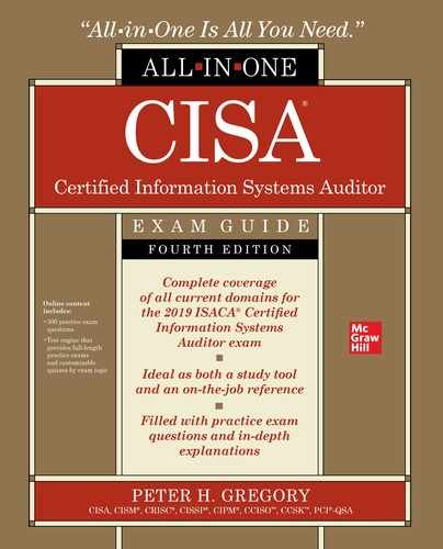
The CPU in modern computers is wholly contained in a single large-scale integration integrated circuit (LSI IC), more commonly known as a microprocessor. A CPU is attached to a computer circuit board (often called a motherboard on a personal computer) by soldering or a plug-in socket. A CPU on a motherboard is shown in Figure 5-2.
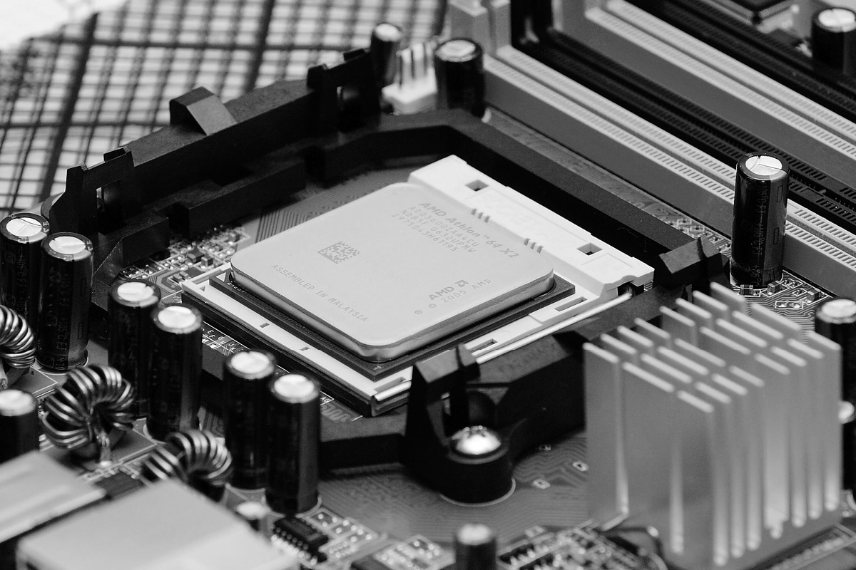
Figure 5-2 A CPU that is plugged into a computer circuit board (Image courtesy of Fir0002/Flagstaffotos)
CPU Architectures A number of architectures dominate the design of CPUs. Two primary architectures that are widely used commercially are
• CISC (complex instruction set computer) This CPU design has a comprehensive instruction set, and many instructions can be performed in a single cycle. This design philosophy claims superior performance over RISC. Well-known CISC CPUs include Intel x86, VAX, PDP-11, Motorola 68000, and System/360.
• RISC (reduced instruction set computer) This CPU design uses a smaller instruction set (meaning fewer instructions in its “vocabulary”), with the idea that a small instruction set will lead to a simpler microprocessor design and better computer performance. Well-known RISC CPUs include Alpha, MIPS, PowerPC, and SPARC. Few of these are produced today, but they are still found in some environments.
Another aspect of CPUs that is often discussed is the power requirements. Typically, the CPUs that are used for laptop computers and mobile devices are known as low-power CPUs, while other CPUs are used in desktop, server, and mainframe systems, where performance and speed are more important considerations than power consumption.
Computer CPU Architectures Early computers had a single CPU. However, it became clear that many computing tasks could be performed more efficiently if computers had more than one CPU to perform them. Some of the ways that computers have implemented CPUs are
• Single CPU In this design, the computer has a single CPU. This simplest design is still prevalent, particularly among small servers and personal computers.
• Multiple CPUs A computer design can accommodate multiple CPUs, from as few as 2 to as many as 128 or more. There are two designs for multi-CPU computers: symmetric and asymmetric. In the symmetric design, all CPUs are equal in terms of how the overall computer’s architecture uses them. In the asymmetric design, one CPU is the “master.” Virtually all multi-CPU computers made today are symmetric.
• Multicore CPUs A change in the design of CPUs themselves has led to multicore CPUs, in which two or more central processors occupy a single CPU chip. The benefit of multicore design is the ability for software code to be executed in parallel, leading to improved performance. Many newer servers and personal computers are equipped with multicore CPUs, and some are equipped with multiple multicore CPUs.
Bus
A bus is an internal component in a computer that provides the means for the computer’s other components to communicate with one another. A computer’s bus connects the CPU with its main and secondary storage as well as to external devices.
Most computers also utilize electrical connectors that permit the addition of small circuit boards that may contain additional memory, a communications device or adaptor (for example, a network adaptor or a modem), a storage controller (for example, a SCSI [Small Computer Systems Interface] or ATA [AT Attachment] disk controller), or an additional CPU.
Several industry standards for computer buses have been developed. Notable standards include
• Universal Serial Bus (USB) This standard is used to connect external peripherals such as external storage devices, printers, and mobile devices. USB operates at data rates up to 40.0 Gbit/sec. USB is discussed in more detail later in this chapter.
• Serial ATA (SATA) This standard is used mainly to connect mass storage devices such as hard disk drives, optical drives, and solid-state drives.
• PCI Express (PCIe) This bus standard replaced older standards such as PCI and PCI-X and employs data rates from 250 Mbyte/sec to 128 Gbyte/sec.
• Thunderbolt This hardware interface standard is a combination of PCI Express and DisplayPort (DP) in a single serial signal.
• PC Card Formerly known as PCMCIA, the PC Card bus is prevalent in laptop computers and is commonly used for the addition of specialized communication devices.
• ExpressCard Also developed by the PCMCIA, this bus standard replaces the PC Card standard.
It is not uncommon for a computer to have more than one bus. For instance, many PCs have an additional front-side bus (FSB), which connects the CPU to a memory controller hub, as well as a high-speed graphics bus, a memory bus, and the low pin count (LPC) bus that is used for low-speed peripherals such as parallel and serial ports, keyboard, and mouse.
Main Storage
A computer’s main storage is used for short-term storage of information. Main storage is usually implemented with electronic components such as random access memory (RAM), which is relatively expensive but also relatively fast in terms of accessibility and transfer rate.
A computer uses its main storage for several purposes:
• Operating system The computer’s running operating system uses main storage to store information about running programs, open files, logged-in users, in-use devices, active processes, and so on.
• Buffers Operating systems and programs will set aside a portion of memory as a “scratch pad” that can be used temporarily to store information retrieved from hard disks or information that is being sent to a printer or other device. Buffers are also used by network adaptors to store incoming and outgoing information temporarily.
• Storage of program code Any program that the computer is currently executing will be stored in main storage so that the CPU can quickly access and read any portion of the program as needed. Note that the program in main storage is only a working copy of the program, used by the computer to reference instructions quickly in the program.
• Storage of program variables When a program is being run, it will store intermediate results of calculations and other temporary data. This information is stored in main storage, where the program can quickly reference portions of it as needed.
Main storage is typically volatile. This means that the information stored in main storage should be considered temporary. If electric power were suddenly removed from the computer, the contents of main storage would vanish and would not be easily recovered, if at all.
Different technologies are used in computers for main storage:
• DRAM (dynamic RAM) In the most common form of semiconductor memory, data is stored in capacitors that require periodic refreshing to keep them charged—hence the term dynamic.
• SRAM (static RAM) This form of semiconductor memory does not require periodic refresh cycles like DRAM.
A typical semiconductor memory module is shown in Figure 5-3.

Figure 5-3 Typical RAM module for a laptop, workstation, or server (Image courtesy of Sassospicco)
Secondary Storage
Secondary storage is the permanent storage used by a computer system. Unlike primary storage (which is usually implemented in volatile RAM modules), secondary storage is persistent and can last many years.
This type of storage is usually implemented using hard disk drives or solid-state drives ranging in capacity from gigabytes to terabytes.
Secondary storage represents an economic and performance tradeoff from primary storage. It is usually far slower than primary storage, but the unit cost for storage is far less costly. At the time of this writing, the price paid for about 16GB of RAM could also purchase a 2TB hard disk drive, which makes RAM (primary) storage more than 1,000 times more expensive than hard disk (secondary) storage. A hard disk drive from a desktop computer is shown in Figure 5-4.
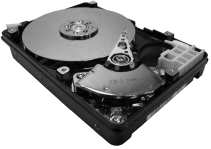
Figure 5-4 Typical computer hard disk drive (Image courtesy of Robert Jacek Tomczak)
A computer uses secondary storage for several purposes:
• Program storage The programs that the computer executes are contained in secondary storage. When a computer begins to execute a program, it makes a working copy of the program in primary storage.
• Data storage Information read into, created by, or used by computer programs is often stored in secondary storage. Secondary storage is usually used when information is needed for use at a later time.
• Computer operating system The set of programs and device drivers that are used to control and manage the use of the computer is stored in secondary storage.
• Temporary files Many computer programs need to store information for temporary use that may exceed the capacity of main memory. Secondary storage is often used for this purpose. For example, a user wants to print a data file onto a nearby laser printer; software on the computer will transform the stored data file into a format that is used by the laser printer to make a readable copy of the file; this “print file” is stored in secondary storage temporarily until the printer has completed printing the file for the user, and then the file is deleted.
• Virtual memory This is a technique for creating a main memory space that is physically larger than the actual available main memory. Virtual memory (which should not be confused with virtualization) is discussed in detail later in this chapter in the section “Computer Operating Systems.”
While secondary storage is usually implemented with hard disk drives, many newer systems use semiconductor flash memory in solid-state drives (SSDs). Flash is a nonvolatile semiconductor memory that can be rewritten and requires no electric power to preserve stored data.
Although secondary storage technology is persistent and highly reliable, hard disk drives and even SSDs are known to fail from time to time. For this reason, important data in secondary storage is often copied to other storage devices, either on the same computer or on a different computer, or it is copied onto computer backup tapes that are designed to store large amounts of data for long periods at low cost. This practice of data backup is discussed at length in the section “Information Systems Operations,” earlier in this chapter.
Firmware
Firmware is special-purpose storage that is used to store the instructions needed to start a computer system. Typically, firmware consists of low-level computer instructions that are used to control the various hardware components in a computer system and to load and execute components of the operating system from secondary storage. This process of system initialization is known as an initial program load (IPL), or bootstrap (or just “boot”).
Read-only memory (ROM) technology is often used to store a computer’s firmware. Several available ROM technologies are in use, including
• ROM The earliest forms of ROM are considered permanent and can never be modified. The permanency of ROM makes it secure, but it can be difficult to carry out field upgrades. For this reason ROM is not often used.
• PROM (programmable read-only memory) This is also a permanent and unchangeable form of storage. A PROM chip can be programmed only once, and it must be replaced if the firmware needs to be updated.
• EPROM (erasable programmable read-only memory) This type of memory can be written to with a special programming device and then erased and rewritten at a later time. EPROM chips are erased by shining ultraviolet (UV) light through a quartz window on the chip; the quartz window is usually covered with a foil label, although sometimes an EPROM chip does not have a window at all, which effectively makes it a PROM device.
• EEPROM (electrically erasable programmable read-only memory) This is similar to EPROM, except that no UV light source is required to erase and reprogram the EEPROM chip; instead, signals from the computer in which the EEPROM chip is stored can be used to reprogram or update the EEPROM. Thus, EEPROM was one of the first types of firmware that could be updated by the computer on which it was installed.
• Flash This memory is erasable, reprogrammable, and functionally similar to EEPROM, in that the contents of flash memory can be altered by the computer that it is installed in. Flash memory is the technology used in popular portable storage devices such as USB memory devices, Secure Digital (SD) cards, Compact Flash, and Memory Stick.
A well-known use for firmware is the ROM-based BIOS (basic input/output system) on Intel-based personal computers.
I/O and Networking
Regardless of their specific purpose, computers nearly always must have some means for accepting input data from some external source as well as for sending output data to some external destination. Whether this input and output are continuous or infrequent, computers usually have one or more methods for transferring data. These methods include
• Input/output (I/O) devices Most computers have external connectors to permit the attachment of devices such as keyboards, mice, monitors, scanners, printers, and cameras. The electrical signal and connector-type standards include PS/2 (for keyboards and mice), USB, parallel, serial, and Thunderbolt. Some types of computers lack these external connectors; instead, special adaptor cards can be plugged into a computer’s bus connector. Early computers required reprogramming and/or reconfiguration when external devices were connected, but newer computers are designed to recognize when an external device is connected or disconnected and will adjust automatically.
• Networking A computer can be connected to a local or wide area data network. Then, one of a multitude of means for inbound and outbound data transfer can be configured that will use the networking capability. Some computers will have built-in connectors or adaptors, but others will require the addition of internal or external adaptors that plug into bus connectors such as PC Card, ExpressCard, PCI, or USB.
Multicomputer Architectures
Organizations that use several computers have a lot of available choices. Not so long ago, organizations that required several servers would purchase individual server computers. Now there are choices that can help to improve performance and reduce capital, including
• Blade computers This architecture consists of a main chassis component that is equipped with a central power supply, cooling, network, and console connectors, with several slots that are fitted with individual CPU modules. The advantage of blade architecture is the lower-than-usual unit cost for each server module, since it consists of only a circuit board. The costs of power supply, cooling, and so on, are amortized among all of the blades. A typical blade system is shown in Figure 5-5.
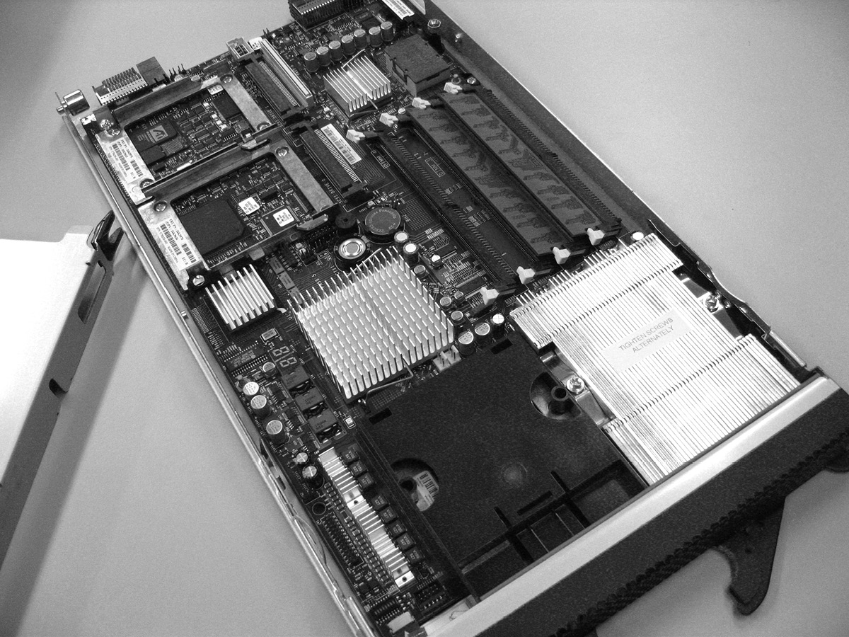
Figure 5-5 Blade computer architecture (Image courtesy of Robert Kloosterhuis)
• Grid computing The term grid computing describes a large number of loosely coupled computers that are used to solve a common task. Computers in a grid may be in close proximity to each other or scattered over a wide geographic area. Grid computing is a viable alternative to supercomputers for solving computationally intensive problems.
• Server clusters A cluster is a tightly coupled collection of computers that is used to solve a common task. In a cluster, one or more servers actively perform tasks, while zero or more computers may be in a “standby” state, ready to assume active duty should the need arise. Clusters usually give the appearance of a single computer to the perspective of outside systems. Clusters usually operate in one of two modes: active-active and active-passive. In active-active mode, all servers perform tasks; in active-passive mode, some servers are in a standby state, waiting to become active in an event called a failover, which usually occurs when one of the active servers has become incapacitated.
These options give organizations the freedom to develop a computer architecture that will meet their needs in terms of performance, availability, flexibility, and cost.
Virtualization Architectures
Virtualization refers to the set of technologies that permits two or more running operating systems (of the same type or different types) to reside on a single physical computer. Virtualization technology enables organizations to use computing resources more efficiently.
Before I explain the benefits of virtualization, I should first state one of the principles of computer infrastructure management. It is a sound practice to use a server for one single purpose. Using a single server for multiple purposes can introduce a number of problems, including
• Tools or applications that reside on a single computer may interfere with one another.
• Tools or applications that reside on a single computer may interact with each other or compete for common resources.
• A tool or application on a server could, although rarely, cause the entire server to stop running; on a server with multiple tools or applications, this could cause the other tools and applications to stop functioning.
Prior to virtualization, the most stable configuration for running many applications and tools was to run each on a separate server. This would, however, result in a highly inefficient use of computers and of capital, as most computers with a single operating system spend much of their time in an idle state.
Virtualization permits IT departments to run many applications or tools on a single physical server, each within its own respective operating system, thereby making more efficient use of computers (not to mention electric power and data center space). Virtualization software emulates computer hardware so that an operating system running in a virtualized environment does not know that it is actually running on a virtual machine. Virtualization software, known as a hypervisor, includes resource allocation configuration settings so that each guest (a running operating system) will have a specific amount of memory, hard disk space, and other peripherals available for its use. Virtualization also facilitates the sharing of peripheral devices such as network connectors so that many guests can use an individual network connector, although each will have its own unique IP address.
Virtualization is the basis of cloud-based Infrastructure-as-a-Service (IaaS) services such as Amazon AWS, Google Cloud, and Microsoft Azure.
Virtualization software provides security by isolating each running operating system and preventing it from accessing or interfering with others. This is similar to the concept of process isolation within a running operating system, where a process is not permitted to access resources used by other processes.
A server with running virtual machines is depicted in Figure 5-6.
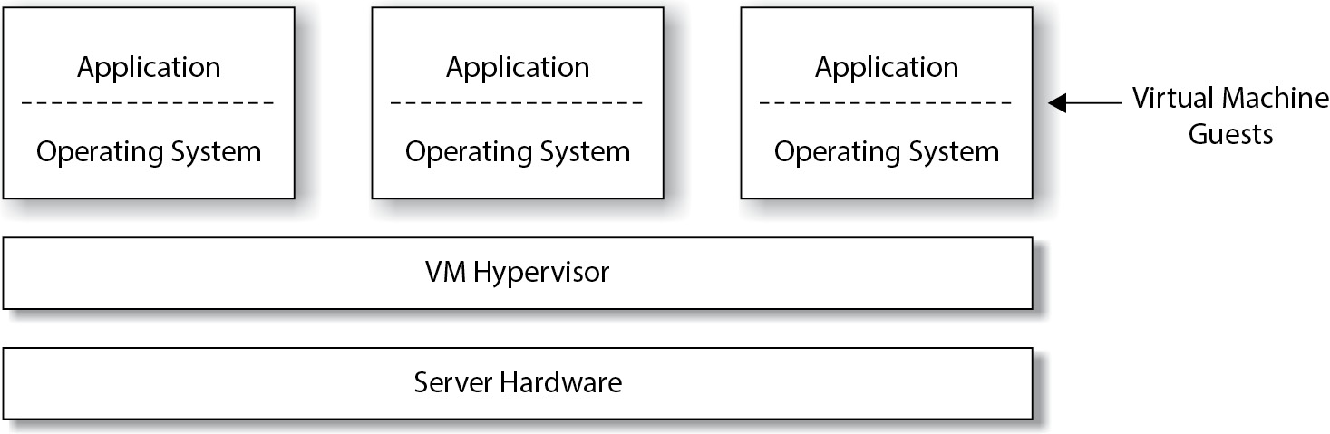
Figure 5-6 Virtualization
Many security issues need to be considered in a virtualization environment, including
• Access control Access to virtualization management and monitoring functions should be restricted to those personnel who require it.
• Resource allocation A virtualization environment needs to be carefully configured so that each virtual machine is given the resources it requires to function correctly and perform adequately.
• Logging and monitoring Virtual environments need to be carefully monitored so that any sign of security compromise will be quickly recognized and acted on.
• Hardening Virtual environments need to be configured so that only necessary services and features are enabled, and all unnecessary services and features are either disabled or removed.
• Vulnerability management Virtualization environments need to be monitored as closely as operating systems and other software so that the IT organization is aware of newly discovered security vulnerabilities and available patches.
Hardware Maintenance
In comparison to computer hardware systems that were manufactured through the 1980s, today’s computer hardware requires little or no preventive or periodic maintenance. And with today’s popular cloud-based computing, some organizations have little or no data center hardware to maintain at all.
Computer hardware maintenance is limited to periodic checks to ensure that the computer is free of dirt and moisture. From time to time, a systems engineer will need to open a computer system cabinet and inspect it for accumulation of dust and dirt, and he or she may need to remove this debris with a vacuum cleaner or filtered compressed air. Depending on the cleanliness of the surrounding environment, inspection and cleaning may be needed as often as every few months or as seldom as every few years.
Maintenance may also be carried out by third-party service organizations that specialize in computer maintenance.
When it is required, hardware maintenance is an activity that should be monitored. Qualified service organizations should be hired to perform maintenance at appropriate intervals. If periodic maintenance is required, management should establish a service availability plan that includes planned downtime when such operations take place.
Automated hardware monitoring tools can provide information that will help determine whether maintenance is needed. Automated monitoring is discussed in the next section.
Hardware Monitoring
Automated hardware monitoring tools can be used to keep a continuous watch on the health and utilization of server and network hardware. In an environment with many servers, this capability can be centralized so that the health of many servers and network devices can be monitored using a single monitoring program.
Hardware monitoring capabilities may vary among different makes of computer systems, but can include any or all of the following:
• CPU Monitoring will indicate whether the system’s CPU is operating properly and whether its temperature is within normal range.
• Power supply Monitoring will show whether the power supply is operating properly, including input voltage, output voltage and current, cooling fans, and temperature.
• Internal components Monitoring will specify whether other internal components such as storage devices, memory, chipsets, controllers, adaptors, and cooling fans are operating properly and within normal temperature ranges.
• Resource utilization Monitoring will measure the amount of resources in use, including CPU, memory, disk storage, and network utilization.
• Asset management Many monitoring systems can track the assets that are present in the environment, giving management an electronic asset inventory capability.
• External environment Monitoring is usually considered incomplete unless the surrounding environment is also monitored. This usually includes temperature, humidity, the presence of water, and vibration in locales where earthquakes are common. Monitoring can also include video surveillance and access door alarms.
Centralized monitoring environments typically utilize the local area network for transmitting information from systems to a central console. Many monitoring consoles have the ability to send alert messages to the personnel who manage the systems being monitored. Often, reports can show monitoring statistics over time so that personnel can identify trends that could be indications of impending failure.
Public cloud IaaS vendors perform hardware monitoring on behalf of their customers.
NOTE Hardware monitoring is often included in network device and network traffic monitoring that is performed by personnel in a NOC.
Information Systems Architecture and Software
This section discusses computer operating systems, data communications, file systems, database management systems, media management systems, and utility software.
Computer Operating Systems
Computer operating systems (which are generally known as operating systems, or OSs) are large, general-purpose programs that are used to control computer hardware and facilitate the use of software applications. Operating systems perform the following functions:
• Access to peripheral devices The operating system controls and manages access to all devices and adaptors that are connected to the computer. This includes storage devices, display devices, and communications adaptors.
• Storage management The operating system provides for the orderly storage of information on storage hardware. For example, operating systems provide file system management for the storage of files and directories on SSDs or hard drives.
• Process management Operating systems facilitate the existence of multiple processes, some of which will be computer applications and tools. Operating systems ensure that each process has private memory space and is protected from interference and eavesdropping by other processes.
• Resource allocation Operating systems facilitate the sharing of resources on a computer such as memory, communications, and display devices.
• Communication Operating systems facilitate communications with users via peripheral devices and also with other computers through networking. Operating systems typically have drivers and tools to facilitate network communications.
• Security Operating systems restrict access to protected resources through process, user, and device authentication.
Examples of popular operating systems include Linux, Solaris, macOS, Android, iOS, Chrome OS, and Microsoft Windows.
The traditional context of the relationship between operating systems and computer hardware is this: one copy of a computer operating system runs on a computer at any given time. Virtualization, however, has changed all of that. Virtualization is discussed earlier in this chapter.
Server Clustering
Using special software, a group of two or more computers can be configured to operate as a cluster. This means that the group of computers will appear as a single computer for the purpose of providing services. Within the cluster, one computer will be active and the other computer(s) will be in passive mode; if the active computer should experience a hardware or software failure and crash, the passive computer(s) will transition to active mode and continue to provide service. This is known as active-passive mode. The transition is called a failover.
Clusters can also operate in active-active mode, where all computers in the cluster provide service; in the event of the failure of one computer in the cluster, the remaining computer(s) will continue providing service.
Grid Computing
Grid computing is a technique used to distribute a problem or task to several computers at the same time, taking advantage of the processing power of each, to solve the problem or complete the task in less time. Grid computing is a form of distributed computing, but in grid computing, the computers are coupled more loosely and the number of computers participating in the solution of a problem can be dynamically expanded or contracted at will.
Cloud Computing
Cloud computing refers to dynamically scalable and usually virtualized computing resources that are provided as a service. Cloud computing services may be rented or leased so that an organization can have scalable application environments without the need for supporting hardware or a data center. Or cloud computing may include networking, computing, and even application services in a Software-as-a-Service (SaaS) or Platform-as-a-Service (PaaS) model. Cloud computing is discussed in more detail in Chapter 4.
Data Communications Software
The prevalence of network-centric computing has resulted in networking capabilities being included with virtually every computer and being built into virtually every computer operating system. Almost without exception, computer operating systems include the ability for the computer to connect with networks based on the TCP/IP suite of protocols, enabling the computer to communicate on a home network, enterprise business network, or the global Internet.
Data communications is discussed in greater detail later in this chapter in the section “Network Infrastructure.”
File Systems
A file system is a logical structure that facilitates the storage of data on a digital storage medium such as a hard drive, SSD, CD/DVD-ROM, or flash memory device. The structure of the file system facilitates the creation, modification, expansion and contraction, and deletion of data files. A file system may also be used to enforce access controls to control which users or processes are permitted to access, alter, or create files in a file system.
It can also be said that a file system is a special-purpose database designed for the storage and management of files.
Modern file systems employ a storage hierarchy that consists of two main elements:
• Directories A directory is a structure that is used to store files. A file system may contain one or more directories, each of which may contain files and subdirectories. The topmost directory in a file system is usually called the “root” directory. A file system may exist as a hierarchy of information, in the same way that a building can contain several file rooms, each of which contains several file cabinets, which contain drawers that contain dividers, folders, and documents. Directories are sometimes called folders in some computing environments.
• Files A file is a sequence of zero or more characters that are stored as a logical whole. A file may be a document, spreadsheet, image, sound file, computer program, or data that is used by a program. A file can be small as zero characters in length (an empty file) or as large as many gigabytes (trillions of characters). A file occupies units of storage on storage media (which could be a hard disk, SSD, or flash memory device, for example) that may be called blocks or sectors; however, the file system hides these underlying details from the user so that the file may be known simply by its name, the directory in which it resides, and its contents.
Well-known file systems in use today include
• FAT (File Allocation Table) This file system has been used in MS-DOS and early versions of Microsoft Windows, and FAT is often used as the file system on portable media devices such as flash drives. Versions of FAT include FAT12, FAT16, and FAT32. FAT does not support security access controls, including specifying access permissions to files and directories. FAT also does not include any journaling features, making it more vulnerable to corruption if power is removed during write operations.
• NTFS (NT File System) This is used in newer versions of Windows, including desktop and server editions. NTFS supports file- and directory-based access control and file system journaling (the process of recording changes made to a file system; this aids in file system recovery).
• EXT3 This journaled file system is used by the Linux operating system.
• HFS (Hierarchical File System) This file system is used on computers running the Apple macOS operating system.
• APFS (Apple File System) This file system is used on computers running the Apple macOS operating system.
• Resilient File System (ReFS) This file system is used on Windows Server 2012 and later versions and is intended to become the replacement for NTFS.
• ISO/IEC 9660 This file system is used by CD-ROM and DVD-ROM media.
• UDF (Universal Disk Format) This optical media file system is considered a replacement for ISO/IEC 9660. UDF is widely used on rewritable optical media.
Database Management Systems
A database management system, or DBMS, is a software program or collection of programs that facilitates the storage and retrieval of potentially large amounts of structured information. A DBMS contains methods for inserting, updating, and removing data; these functions can be used by computer programs and software applications. A DBMS also usually contains authentication and access control, thereby permitting control over which users may access what data.
DBMS Organization
Most DBMSs employ a data definition language (DDL) that is used to define the structure of the data contained in a database. The DDL defines the types of data stored in the database as well as relationships between different portions of that data.
DBMSs employ some sort of a data dictionary (DD) or directory system (DS) that is used to store information about the internal structure of databases stored in the DBMS.
To understand how they relate to each other, you can think of the DDL as the instructions for building a database’s structure and data relationships; the DD or DS is where the database’s structure and relationships are stored and used by the DBMS.
DBMSs also employ a data manipulation language (DML) that is used to insert, delete, and update data in a database. SQL is a popular DML that is used in the Oracle and SQL Server DBMSs.
DBMS Structure
There are three principal types of DBMSs in use today: relational, object, and hierarchical. Each is described in this section.
Relational Database Management Systems Relational database management systems (RDBMSs) represent the most popular model used for DBMSs. A relational database permits the design of a structured, logical representation of information.
Many relational databases are accessed and updated through the SQL (Structured Query Language) computer language. Standardized in ISO/IEC and ANSI standards, SQL is used in many popular relational DBMS products, including Oracle Database, Microsoft SQL Server, MySQL, and IBM DB2.
RDBMS Basic Concepts A relational database consists of one or more tables. A table can be thought of as a simple list of records, like lines in a data file. The records in a table are often called rows. The different data items that appear in each row are usually called fields.
A table often has a primary key. This is simply one of the table’s fields whose values are unique in the table. For example, a table of healthcare patient names can include each patient’s identification number, which can be made the primary key for the table.
One or more indexes can be built for a table. An index facilitates rapid searching for specific records in a table based upon the value of one of the fields other than the primary key. For instance, a table that contains a list of assets and their serial numbers can have an index of the table’s serial numbers. This will permit a rapid search for a record containing a specific serial number; without the index, RDBMS software would have to examine every record in the table sequentially until the desired records are found.
One of the most powerful features of a relational database is the use of foreign keys. A foreign key is a field in a record in one table that can reference a primary key in another table. For example, a table that lists sales orders includes fields that are foreign keys, each of which references records in other tables. This is shown in Figure 5-7.
Figure 5-7 Fields in a sales order table point to records in other tables.
Relational databases enforce referential integrity. This means that the database will not permit a program (or user) to delete a row from a table if there are records in other tables whose foreign keys reference the row to be deleted. The database instead will return an error code that will signal to the requesting program that there are rows in other tables that would be “stranded” if the row was deleted. Using the example in Figure 5-7, a relational database will not permit a program to delete salesperson #2 or #4 since there are records in the sales order table that reference those rows.
The power of relational databases comes from their design and from SQL. Queries are used to find one or more records from a table using the SELECT statement. An example statement is
![]()
One powerful feature in relational databases is a special query called a join, where records from two or more tables are searched in a single query. An example join query is

This query will produce a list of salespersons and the number of orders they have sold.
Relational Database Security Relational databases in commercial applications need to have some security features. Three primary security features are
• Access controls Most relational databases have access controls at the table and field levels. This means that a database can permit or deny a user the ability to read data from or write data to a specific table or even a specific field. To enforce access controls, the database needs to authenticate users so that it knows the identity of each user making access requests. DBMSs employ a data control language (DCL) to control access to data in a database.
• Encryption Sensitive data such as financial or medical records may need to be encrypted. Some relational databases provide field-level database encryption that permits a user or application to specify certain fields that should be encrypted. Encryption protects the data by making it difficult to read if an intruder is able to obtain the contents of the database by some illicit means.
• Audit logging DBMSs provide audit logging features that permit an administrator or auditor to view some or all activities that take place in a database. Audit logging can show precisely the activities that take place, including details of database changes and the user who made those changes. The audit logs themselves can be protected so that they resist tampering, which can make it difficult for someone to make changes to data and erase their tracks.
Database administrators can also create views, which are virtual tables created via stored queries. Views can simplify viewing data by aggregating or filtering data. They can improve security by exposing only certain records or fields to users.
NoSQL NoSQL DBMSs are nonrelational and designed to support large, sometimes disparate data sets across multiple systems. Several types of NoSQL databases are in use, including Column, Document, Key-Value, and Graph.
The motivation for the use of NoSQL databases is primarily applicability and usefulness: relational databases are not always the best choice for a DBMS in every application.
Object Database Management Systems An object database (or object database management system, ODBMS) is a database where information is represented as objects that are used in object-oriented programming languages. Object-oriented databases are used for data that does not require static or predefined attributes, such as a fixed-length field or defined data structure. The data can even be of varying types. The data that is contained in an object-oriented database is unpredictable in nature.
Unlike the clean separation between programs and data in the relational database model, object databases make database objects appear as programming language objects. Both the data and the programming method are contained in an object. Object databases are really just the mechanisms used to store data that is inherently part of the basic object-oriented programming model. Thus, when a data object is accessed, the data object itself will contain functions (methods), negating the requirement for a query language such as SQL.
Object databases are not widely used commercially. They are limited to a few applications requiring high-performance processing on complex data.
Relational databases are starting to look a little more like object databases through the addition of object-oriented interfaces and functions; object-oriented databases are starting to look a little more like relational databases through query languages such as Object Query Language (OQL).
Hierarchical Database Management Systems A hierarchical database is so named because its data model is a top-down hierarchy, with parent records and one or more child records in its design. The dominant hierarchical database management system product in use today is IBM’s IMS (Information Management System) that runs on mainframes in nearly all of the larger organizations in the world.
A network database is similar to a hierarchical database, extended somewhat to permit lateral data relationships (like the addition of “cousins” to the parent and child records). Figure 5-8 illustrates hierarchical and network databases.

Figure 5-8 Hierarchical and network databases
Media Management Systems
Information systems may employ automated tape management systems (TMSs) or disk management systems (DMSs) that track the tape and disk volumes that are needed for application processing.
Disk and tape management systems instruct system operators to mount specific media volumes when they are needed. These systems reduce operator error by requesting specific volumes and rejecting incorrect volumes that do not contain the required data.
TMSs and DMSs are most often found as a component of a computer backup system. Most commercial backup systems track which tape or disk volumes contain which backed-up files and databases. Coupled with automatic volume recognition (usually through barcode readers), backup systems maintain an extensive catalog of the entire collection of backup media and their contents. When data needs to be restored, the backup software (or the TMS or DMS) will specify which media volume should be mounted, verify that the correct media is available, and then restore the desired data as directed.
Significant reductions in the cost of storage, together with the trend toward cloud computing and cloud storage, have resulted in few new installations of TMSs and DMSs. Still, many organizations utilize these today, and IS auditors must be familiar with their function and operation.
Utility Software
Utility software comprises a broad class of programs that support the development or use of networks, information systems, operating systems, and applications. Utility software is most often used by IT specialists whose responsibilities include some aspect of system development, support, or operations. End users, on the other hand, most often use software applications instead of utilities.
Utility software can be classified into the following categories:
• Software and data design This includes system, program, and data modeling tools that are used to design new applications or to model existing applications.
• Software development These programs are used to facilitate the actual coding of an application (or another utility). Development tools can provide a wide variety of functions, including program language syntax checking, compilation, debugging, and testing.
• Software testing Apart from unit testing that may be present in a development environment, dedicated software testing tools perform extensive testing of software functions. Automated testing tools can contain entire suites of test cases that are run against an application program, with the results stored for future reference.
• Security testing Several different types of software tools are used to determine the security of software applications, operating systems, DBMSs, and networks. One type of security testing tool examines an application’s source code, looking for potential security vulnerabilities. Another type runs the application program and inputs different forms of data to see if the application contains vulnerabilities in the way that it handles this data. Other security testing tools examine operating system and DBMS configuration settings. Still others send specially crafted network messages to a target system to see what types of vulnerabilities might exist that could be exploited by an intruder or a hacker.
• Data management These utilities are used to manipulate, list, transform, query, compare, encrypt, decrypt, import, or export data. They may also test the integrity of data (for instance, examining an index in a relational database or the integrity of a file system) and possibly make repairs.
• System health These utilities are used to assess the health of an operating system by examining configuration settings; verifying the versions of the kernel, drivers, and utilities; and making performance measurements and tuning changes. Some system utilities are used to assess the health of system components including CPU, main memory, secondary storage, and peripherals.
• Network These utilities are used to examine the network to discover other systems connected to it, determine network configuration, and listen to network traffic.
Utilities and Security
Because some utilities are used to observe or make changes to access controls or security, organizations should limit the use of utilities to those personnel whose responsibilities require their use. All other personnel should not be permitted to use them.
Because many utilities are readily available, simply posting a policy will not prevent their use. Instead, strict access controls should be established so that unauthorized users who do obtain utilities would derive little or no use from them. These controls are typically implemented through one of two methods:
• Remove local administrator privileges from end users on their workstations so that they are unable to install software packages or change the configuration of their workstations’ operating systems.
• Employ software whitelisting software that prohibits all but strictly permitted software programs from running on users’ workstations.
Software Licensing
Most organizations purchase many software components in support of their software applications and IT environments overall. For example, organizations often purchase operating systems, software development tools, DBMSs, web servers, network management tools, office automation systems, and security tools. Organizations need to be aware of the licensing terms and conditions for each of the software products that they lease or purchase.
To be effective, an organization should centralize its records and expertise in software licensing to avoid licensing issues that could lead to unwanted and potentially costly and embarrassing legal actions. Some of the ways that an organization can organize and control its software usage include
• Develop policy The organization should develop policies that define acceptable and unacceptable uses of software.
• Centralize procurement This can help to funnel purchasing through a group or department that can help to manage and control software acquisition and use.
• Implement software metering Automated tools that are installed on each computer (including user workstations) can alert IT of every software program that is installed and run in the organization. This can help to raise awareness of any new software programs that are being used as well as the numbers of copies of programs installed and in use.
• Implement concurrent licensing The organization can use dynamic license management that controls the number of users who are able to use a program simultaneously. This can help reduce costs for expensive programs used infrequently by many employees.
• Review software contracts The person or group with responsibility for managing software licensing should be aware of the terms and conditions of use.
Digital Rights Management
The Internet has provided a means for easily distributing content to large numbers of people. This ability, however, sometimes runs afoul of legal copyright protection afforded to the owners of copyrighted work. This encompasses software programs as well as documents and media.
Organizations also are faced with the problem of limiting the distribution of documents for privacy or intellectual property protection. For example, an organization may publish a technical whitepaper describing its services and desires that only its current customers be able to view the document.
Digital rights management (DRM) is a set of emerging technologies that permits the owner of digital information (such as documents) to control access to that information, even after it is no longer contained in the owner’s environment. In some instances, these technologies are implemented in system hardware (such as electronic book readers), and in other cases they are implemented in software.
Whether implemented in hardware or software, the program or device displaying information will first examine the file to determine whether the information should be displayed or not. Some of the characteristics that the owner of a file may be able to set include
• Expiration The owner of a file may be able to set an expiration date, after which time the file cannot be viewed or used.
• Registration The owner of a file may be able to require anyone viewing the file to register him- or herself in a reliable way (such as through e-mail address verification).
• Authentication The owner of a file may be able to require that persons viewing a file first authenticate themselves.
Network Infrastructure
Networks are used to transport data from one computer to another, either within an organization or between organizations. Network infrastructure is the collection of devices and cabling that facilitates network communications among an organization’s systems as well as among the organization’s systems and those belonging to other organizations. This section describes the following network infrastructure topics:
• Enterprise architecture
• Network architecture
• Network-based services
• Network models
• Network technologies
• Local area networks
• Wide area networks
• Wireless networks
• The TCP/IP suite of protocols
• The global Internet
• Network management
• Networked applications
Enterprise Architecture
There are two distinct facets related to the term enterprise architecture. The first is the overall set of infrastructure that facilitates access to applications and information: the networks, whether wired or wireless, local or wide area, together with resilience, access controls, and monitoring; the systems with their applications and tools; and the data and where it is stored, transmitted, and processed. The second facet is the ongoing activity carried out by one or more persons with titles such as Enterprise Network Architect, Enterprise Data Architect, Enterprise Systems Engineer, or Enterprise Security Architect, any and all of whom are concerned with “big picture” aspects of the organization and its mission, objectives, and goals, and whether the organization’s infrastructure as a whole contributes to their fulfillment.
Enterprise architecture, done correctly, requires standards: consistent ways of doing things, and consistency in the components that are used and how those components are configured.
The goals of enterprise architecture include
• Scalability Enterprise architects should design the whole enterprise and its components so that systems, networks, and storage can be easily expanded where needed.
• Agility The overall design of the organization’s infrastructure should be flexible enough to meet new goals and objectives.
• Transparency High-level and detailed diagrams should be readily available and up-to-date. There should be no secrets.
• Security The design of an organization’s infrastructure should reflect the needs of the organization through means such as segmentation, the creation of security zones, monitoring, and the inclusion of security components including firewalls and intrusion prevention systems.
• Consistency The organization’s infrastructure should reflect consistency through the use of common components and configurations. This makes troubleshooting and upkeep more effective when engineers are familiar with micro architectures, components, and configurations. For example, an organization with retail stores or branch offices should employ identical architectures in each of those locations; this makes support and troubleshooting easier because engineers don’t first need to figure out how a local network is configured—they’re all the same, or nearly so.
• Repeatability Consistency brings repeatability. In an organization with retail stores or branch offices, for instance, additions or changes are “cookie cutter” instead of time-consuming “one-off” efforts.
• Efficiency Repeatability and consistency yield efficiency. Upgrades, expansion, and configuration changes are consistent and repeatable. Troubleshooting takes less time.
• Resilience Enterprise architects need to understand where resilience is required, so that infrastructure will be continuously available even in the event of the failure of individual components, or in cases of maintenance.
The challenge facing many organizations is the temptation to cut corners and deviate from (or never implement) standard architectures. Short-term gains are almost sure to be smaller than long-term inefficiencies realized later. Vision and discipline are required to attain, and maintain, a consistent and effective enterprise architecture.
Network Architecture
The term network architecture has several meanings, all of which refer to the overall design of an organization’s network communications. An organization’s network architecture, like other aspects of its information technology, should support the organization’s mission, goals, and objectives.
The facets of network architecture include
• Physical network architecture This is concerned with the physical locations of network equipment and media. This includes, for instance, the design of a network cable plant (also known as structured cabling), as well as the locations and types of network devices. An organization’s physical network architecture may be expressed in several layers. A high-level architecture may depict global physical locations or regions and their interconnectivity, while an in-building architecture will be highly specific regarding the types of cabling and locations of equipment.
• Logical network architecture This is concerned with the depiction of network communications at a local, campus, regional, and global level. Here, the network architecture will include several related layers, including representations of network protocols, device addressing, traffic routing, security zones, and the utilization of carrier services.
• Data flow architecture This is closely related to application and data architecture. Here, the flow of data is shown as connections among applications, systems, users, partners, and suppliers. Data flow can be depicted in nongeographic terms, although representations of data flow at local, campus, regional, and global levels are also needed, since geographic distance is often inversely proportional to capacity and throughput.
• Network standards and services This is more involved with the services that are used on the network and less with the geographic and spatial characteristics of the network. Services and standards need to be established in several layers, including cable types, addressing standards, routing protocols, network management protocols, utility protocols (such as Domain Name System [DNS], Network Time Protocol [NTP], file sharing, printing, e-mail, remote access, and many more), and application data interchange protocols, such as SOA (Service-Oriented Architecture), SOAP (Simple Object Access Protocol), and XML (eXtensible Markup Language).
• Security architecture This includes the creation of trust zones, segmentation, and security controls such as firewalls, intrusion prevention systems (IPSs), web content filtering, proxy servers, gateways, and security monitoring.
Types of Networks
Computer networks can be classified in a number of different ways. The primary method of classification is based on the size of a network. By size, we refer not necessarily to the number of nodes or stations on the network, but to its physical or geographic size. These types are (from smallest to largest)
• Personal area network (PAN) Also known as a piconet, a PAN is generally used by a single individual. Its reach ranges from a few centimeters up to 3 meters and is used to connect peripherals and communication devices for use by an individual.
• Local area network (LAN) The original type of network, a LAN connects computers and devices together in a small building or a residence. The typical maximum size of a LAN is 100 meters, which is the maximum cable length for popular network technologies such as Ethernet.
• Campus area network (CAN) A CAN connotes the interconnection of LANs for an organization that has buildings in close proximity.
• Metropolitan area network (MAN) The MAN network spans a city or regional area. Usually, this type of network consists of two or more in-building LANs in multiple locations that are connected by telecommunications circuits (such as Multiprotocol Label Switching [MPLS], T-1, Frame Relay, or dark fiber) or private network connections over the global Internet.
• Wide area network (WAN) A WAN’s size can range from regional to international. An organization with multiple locations across vast distances will connect its locations together with dedicated telecommunications connections or protected connections over the Internet. It is noted that an organization will also call a single point-to-point connection between two distant locations a “WAN connection.”
The classifications discussed here are not rigid, nor do they impose restrictions on the use of any specific technology from one to the next. Instead, they are simply a set of terms that enable professionals to speak easily about the geographic extent of their networks with easily understood terms.
The relative scale of these network terms is depicted in Figure 5-9.
Figure 5-9 A comparison of network sizes
Network-Based Services
Network-based services are the protocols and utilities that facilitate system- and network-based resource utilization. In a literal sense, many of these services operate on servers; they are called network-based services because they facilitate or utilize various kinds of network communication.
Some of these services are
• E-mail E-mail servers collect, store, and transmit e-mail messages from person to person. They accept incoming e-mail messages from other users on the Internet and likewise send e-mail messages over the Internet to e-mail servers that accept and store e-mail messages for distant recipients.
• Print Print servers act as aggregation points for network-based printers in an organization. When users print a document, their workstation sends it to a specific printer queue on a print server. If other users are also sending documents to the same printer, the print server will store them temporarily until the printer is able to print them.
• File storage File servers provide centralized storage of files for use among groups of users. Often, centralized file storage is configured so that files stored on remote servers logically appear to be stored locally on user workstations.
• Directory These services provide centralized management of resource information. Examples include DNS, which provides translation between resource name and IP address, and Lightweight Directory Access Protocol (LDAP), which provides directory information for users and resources, and is often used as a central database of user IDs and passwords. An example of an LDAP-based directory service is Active Directory, which is the Microsoft implementation of and extensions to LDAP.
• Remote access Network- and server-based services within an organization’s network are protected from Internet access by firewalls and other means. This makes them available only to users whose workstations are physically connected to the enterprise network. Remote access permits authorized users to access network-based services remotely from anywhere on the Internet via an encrypted “tunnel” that logically connects the users to the enterprise network as though they were physically there. These virtual private networks (VPNs) are typically encrypted to prevent any eavesdropper from being able to view the contents of a user’s network communication.
• Terminal emulation In many organizations with mainframe computers, PCs have replaced “green screen” and other types of mainframe-centric terminals. Terminal emulation software on PCs enables them to function like those older mainframe terminals.
• Virtual workstation Many organizations implement a virtual desktop infrastructure (VDI), wherein its workstations run operating systems that are actually stored on central servers. This simplifies the administration of those user operating systems since they are centrally stored.
• Time synchronization It is a well-known fact among systems engineers that the time clocks built in to most computers are not very accurate (some are, in fact, notoriously inaccurate). Distributed applications and network services have made accurate “timestamping” increasingly important. Time synchronization protocols enable an organization’s time server system to ensure that all other servers’ and workstations’ time clocks are synchronized. And the time server itself will synchronize with one of several reliable Internet-based time servers, GPS-equipped time servers, or time servers that are attached to international standard atomic clocks.
• Network connectivity and authentication Many organizations have adopted one of several available methods that authenticate users and workstations before logically connecting them to the enterprise network. This helps to prevent nonorganization-owned or noncompliant workstations from being able to connect to an internal network, which is a potential security threat. Users or workstations that are unable to authenticate are connected to a “quarantine” network, where users can obtain information about the steps they need to take to get connected to enterprise resources. Network-based authentication can even quickly examine an organization workstation, checking it for proper security settings (anti-malware, firewall, security patches, security configuration, and so on), and allow it to connect logically only if the workstation is configured properly. Various protocols and technologies that are used to connect, verify, and authenticate devices to a network include Dynamic Host Configuration Protocol (DHCP), 802.1X, and network access control (NAC).
• Web security Most organizations have a vested interest in having some level of control over the choice of Internet web sites that their employees choose to visit. Web sites that serve no business purpose (for example, online gambling, porn, and online games) can be blocked so that employees cannot access them. Further, many Internet web sites (even legitimate ones) host malware that can be automatically downloaded to user workstations. Web security appliances can examine incoming content for malware, in much the same way that a workstation checks incoming files for viruses.
• Cloud access control Many organizations utilize a cloud access security broker (CASB) system to monitor and control access to cloud-based services, as a part of an overall data management and data protection program. A CASB can prevent users from uploading sensitive internal information to a nonsanctioned cloud storage service, for instance.
• Anti-malware Malware (viruses, worms, Trojan horses, and so on) remains a significant threat to organizations. Antivirus software on each workstation is still an important line of defense. Because of the complexity of anti-malware, many organizations have opted to implement advanced anti-malware solutions along with centralized management and control. Using a central anti-malware console, security engineers can quickly spot workstations under attack, as well as those whose anti-malware is not functioning, and they can force new anti-malware updates to some or all user workstations. They can even force user workstations to commence an immediate whole-disk scan for malware if an outbreak has started. Centralized anti-malware consoles can also receive virus infection alerts from workstations and keep centralized statistics on virus updates and outbreaks, giving security engineers a vital “big picture” status.
• Network management Larger organizations with too many servers and network devices to administer manually often turn to network management systems. These systems serve as a collection point for all alerts and error messages from vital servers and network devices. They can also be used to configure network devices centrally, making wide-scale configuration changes possible by a small team of engineers working in a NOC. Network management systems also measure network performance, throughput, latency, and outages, giving network engineers vital information on the health of the enterprise network.
Network Models
Network models are the archetype of the actual designs of network protocols. While a model is often a simplistic depiction of a more complicated reality, the Open Systems Interconnection (OSI) and TCP/IP network models accurately illustrate what is actually happening in a network. It is fairly difficult to actually see the components of the network in action; the models help us to understand how they work.
These models were developed to build consensus among the various manufacturers of network components (from programs, to software drivers, to network devices and cabling) to improve interoperability between different types of computers. In essence, it was a move toward networks with “interchangeable parts” that would facilitate data communications on a global scale.
The two dominant network models that are used to illustrate networks are OSI and TCP/IP. Both are described in this section.
The OSI Network Model
The first widely accepted network model is the Open Systems Interconnection model. The OSI model was developed by the International Organization for Standardization (ISO) and the International Telecommunications Union (ITU). The working groups that developed the OSI model ignored the existence of the TCP/IP model, which was gaining in popularity around the world and has become the de facto world standard.
The OSI model consists of seven layers. Messages that are sent on an OSI network are encapsulated; a message that is constructed at layer 7 is placed inside of layer 6, which is then placed inside of layer 5, and so on. This is not figurative—this encapsulation literally takes place and can be viewed using tools that show the detailed contents of packets on a network. Encapsulation is illustrated in Figure 5-10.
Figure 5-10 Encapsulation of packets in the OSI network model
The layers of the OSI model are, from bottom to top,
• Physical
• Data link
• Network
• Transport
• Session
• Presentation
• Application
Because it is difficult for many people to memorize a list such as this, there are some memory aids to help remember the sequence of these layers, including the following:
• Please Do Not Throw Sausage Pizza Away
• Please Do Not Touch Steve’s Pet Alligator
• All People Seem To Need Data Processing
• All People Standing Totally Naked Don’t Perspire
The layers of the OSI model are explained in more detail in the remainder of this section.
OSI Layer 1: Physical The physical layer in the OSI model is concerned with electrical and physical specifications for devices. This includes communications cabling, voltage levels, and connectors, as well as some of the basic specifications for devices that would connect to networks. At the physical layer, networks are little more than electric signals flowing in wires or radiofrequency airwaves.
At this layer, data exists merely as bits; there are no frames, packets, or messages here. The physical layer also addresses the modulation of digital information into voltage and current levels in the physical medium.
Examples of OSI physical layer standards include
• Cabling 10BASE-T, 100BASE-TX, 1000BASE-X, twinax, and fiber optics, which are standards for physical network cabling
• Communications RS-232, RS-449, and V.35, which are standards for sending serial data between computers
• Telecommunications T1, E1, SONET (Synchronous Optical Networking), DSL (Digital Subscriber Line), and DOCSIS (Data Over Cable Service Interface Specification), which are standards for common carrier communications networks for voice and data
• Wireless communications Asynchronous Connection-Less (ACL) used by Bluetooth, 802.11a PHY (meaning the physical layer component of 802.11), and other wireless local area network (WLAN) airlink standards
• Wireless telecommunications LTE (Long Term Evolution), WiMAX (Worldwide Interoperability for Microwave Access), CDMA (Code Division Multiple Access), W-CDMA, CDMA2000, TDMA (Time Division Multiple Access), and UMTS (Universal Mobile Telecommunications Service), which are airlink standards for wireless communications between cell phones and base stations (these standards also include some OSI layer 2 features)
OSI Layer 2: Data Link The data link layer in the OSI model focuses on the method of transferring data from one station on a network to another station on the same local network. In the data link layer, information is arranged into frames and transported across the medium. Error correction is usually implemented as collision detection, as well as the confirmation that a frame has arrived intact at its destination, usually through the use of a checksum.
This layer is concerned only with communications on a LAN. At the data link layer, there are no routers (or routing protocols). Instead, the layer should be thought of as a collection of locally connected computers to a single physical medium. Data link layer standards and protocols are concerned only with getting a frame from one computer to another on that local network.
Examples of data link layer standards include
• LAN protocols Ethernet, Token Ring, ATM (Asynchronous Transfer Mode), FDDI (Fiber Distributed Data Interface), and Fibre Channel are the protocols used to assemble a stream of data into frames for transport over a physical medium (the physical layer) from one station to another on a LAN. These protocols include error correction, primarily through collision detection, collision avoidance, synchronous timing, or tokens.
• 802.11 MAC/LLC This is the data link portion of the well-known Wi-Fi (wireless LAN) protocols.
• Common carrier packet networks MPLS and Frame Relay are packet-oriented standards for network services provided by telecommunications carriers. Organizations that required point-to-point communications with various locations would often obtain an MPLS or Frame Relay connection from a local telecommunications provider. Frame Relay is being replaced by MPLS and is rapidly declining in use.
• ARP (Address Resolution Protocol) This protocol is used when one station needs to communicate with another and the initiating station does not know the receiving station’s network link layer (hardware) address. ARP is prevalent in TCP/IP networks but is used in other network types as well.
• Point-to-Point (PPP) and Serial Line Internet Protocol (SLIP) These protocols are used to transport TCP/IP packets over point-to-point serial connections (usually RS-232). SLIP is now obsolete, and PPP is generally seen only in remote access connections that utilize dial-up services.
• Tunneling PPTP (Point-to-Point Tunneling Protocol), L2TP (Layer 2 Tunneling Protocol), and other tunneling protocols were developed as a way to extend TCP/IP (among others) from a centralized network to a branch network or a remote workstation, usually over a dial-up connection.
In the data link layer, stations on the network must have an address. Ethernet and Token Ring, for instance, use MAC (Media Access Control) addresses, which are considered hardware addresses. Most other multistation protocols also utilize some form of hardware addressing for each device on the network.
OSI Layer 3: Network The purpose of the OSI network layer is the delivery of messages from one station to another via one or more networks. The network layer can process messages of any length and will “fragment” messages so that they are able to fit into packets that the network is able to transport.
The network layer is concerned with the interconnection of networks and the packet routing between networks. Network devices called routers are used to connect networks. Routers are physically connected to two or more logical networks and are configured with (or have some ability to learn) the network settings for each network. Using this information, routers are able to make routing decisions that will enable them to forward packets to (or closer to) the correct network, moving them closer to their ultimate destination.
Examples of protocols at the network layer include
• IP (Internet Protocol) This network layer protocol is used in the TCP/IP suite of protocols. IP is concerned with the delivery of packets from one station to another, whether the stations are on the same network or on different networks. IP has the IP address scheme for assigning addresses to stations on a network; this is entirely separate from link layer (hardware) addressing such as Ethernet’s MAC addressing. IP is the basis for the global Internet.
• IPsec (Internet Protocol Security) This protocol is used to authenticate, encapsulate, and encrypt IP traffic between networks. This protocol is often used for VPNs facilitating secure remote access.
• ICMP (Internet Control Message Protocol) This communications diagnostics protocol is also a part of the TCP/IP suite. One of its primary uses is the transmission of error messages from one station to another; these error messages are usually related to problems encountered when attempting to send packets from one station to another.
• IGMP (Internet Group Management Protocol) This protocol is used to organize multicast group memberships between routers. IGMP is a part of the multicast protocol family.
• Logical link control and adaptation protocol (L2CAP) This is the network layer used by Bluetooth.
• AppleTalk This original suite of protocols was developed by Apple Computer for networking the Apple brand of computers. The suite of protocols includes the transmission of messages from one computer over interconnected networks, as well as routing protocols. AppleTalk has since been deprecated in favor of TCP/IP.
OSI Layer 4: Transport The transport layer in the OSI model is primarily concerned with the reliability of data transfer between systems. The transport layer manages the following characteristics of data communications:
• Connection orientation At the transport layer, communications between two stations can take place in the context of a connection. Here, two stations will initiate a unique, logical context (called a connection) under which they can exchange messages until a later time when the stations agree to end the connection. Stations can have two or more unique connections established concurrently; each is uniquely identified.
• Guaranteed delivery Protocols at the transport layer can track individual packets to guarantee delivery. For example, the TCP uses something like a return receipt for each transported packet to confirm that each sent packet was successfully received by the destination.
• Sequence of delivery The transport layer includes protocols that are able to track the sequence in which packets are delivered. Typically, each transported packet will have a serialized number that the receiving system will use to make sure that packets on the receiving system are delivered in proper order. When coupled with guaranteed delivery, a receiving system can request retransmission of any missing packets, ensuring that none are lost.
The protocols at the transport layer are doing the heavy lifting by ensuring the integrity and completeness of messages that flow from system to system. The ability for data communications to take place over the vast worldwide network that is the global Internet is made possible by the characteristics of protocols in the transport layer.
Examples of transport layer protocols include
• TCP (Transmission Control Protocol) This is the “TCP” in the TCP/IP protocol suite. TCP is connection-oriented due to the formal establishment (three-way handshake) and maintenance (sequence numbers and acknowledgments) of a connection, using flags to indicate connection state. When a system sends a TCP packet to another system on a specific port, that port number helps the operating system direct the message to a specific program. For example, port 25 is used for inbound e-mail, ports 20 and 21 are used for FTP (File Transfer Protocol), and ports 80 and 443 are used for HTTP (Hypertext Transfer Protocol) and HTTPS (HTTP Secure), respectively. Hundreds of preassigned port numbers are the subject of Internet standards. TCP employs guaranteed delivery and guaranteed order of delivery.
• UDP (User Datagram Protocol) This is the other principal protocol used by TCP/IP in the OSI transport layer. Unlike TCP, UDP is a lighter weight protocol that lacks connection orientation, order of delivery, and guaranteed delivery. UDP consequently has less computing and network overhead, which makes it ideal for some protocols that are less sensitive to occasional packet loss. Examples of protocols that use UDP are DNS (Domain Name System), TFTP (Trivial File Transfer Protocol), and VoIP (Voice over IP). Like TCP, UDP also employs port numbers so that incoming packets on a computer can be delivered to the right program or process. Sometimes UDP is called “unreliable data protocol,” a memory aid that is a reference to the protocol’s lack of guaranteed delivery.
The TCP/IP suite of protocols is described in more detail later in this chapter.
OSI Layer 5: Session The session layer in the OSI model is used to control connections that are established between applications on the same, or different, systems. This involves connection establishment, termination, and recovery.
In the OSI model, connection control takes place in the session layer. This means that the concept of the establishment of a logical connection between systems is a session layer function. However, TCP—which is generally thought of as a transport layer protocol—handles this on its own.
Examples of session layer protocols include
• Interprocess communications Sockets and named pipes are some of the ways that processes on a system (or on different systems) exchange information.
• SIP (Session Initiation Protocol) SIP is used to set up and tear down VoIP and other communications connections.
• RPC (Remote Procedure Call) This is another interprocess communication technology that permits an application to execute a subroutine or procedure on another computer.
• NetBIOS (Network Basic Input/Output System) This permits applications to communicate with one another using the legacy NetBIOS API.
OSI Layer 6: Presentation The presentation layer in the OSI model is used to translate or transform data from lower layers (session, transport, and so on) into formats that the application layer can work with. Examples of presentation layer functions include
• Character set translation Programs or filters are sometimes needed to translate character sets between ASCII and EBCDIC (Extended Binary Coded Decimal Interchange Code), for instance.
• Encryption/decryption Communications may be encrypted if data is to be transported across unsecure networks. Example protocols are SSL (Secure Sockets Layer), TLS (Transport Layer Security), and MIME (Multipurpose Internet Mail Extensions).
• Codecs Protocols such as MPEG (Moving Picture Experts Group) use codecs to encode/decode or to compress/decompress audio and video data streams.
OSI Layer 7: Application The application layer in the OSI model contains programs that communicate directly with the end user. This includes utilities that are packaged with operating systems, as well as tools and software applications.
Examples of application layer protocols include
• Utility protocols DNS, SNMP (Simple Network Management Protocol), DHCP, and NTP
• Messaging protocols SMTP (Simple Mail Transfer Protocol), NNTP (Network News Transfer Protocol), HTTP, VoIP, X.400, and X.500
• Data transfer protocols NFS (Network File System) and FTP
• Interactive protocols Telnet, IRC (Internet Relay Chat), SSH
End-user applications that communicate over networks do so via OSI layer 7.
The TCP/IP Network Model
The TCP/IP network model is one of the basic design characteristics of the TCP/IP suite of protocols. The network model consists of four “layers,” where each layer is used to manage some aspect of the transmission, routing, or delivery of data over a network. In a layered model, each layer receives services from the next lowest layer and provides services to the next higher layer.
Like OSI, the TCP/IP network model utilizes encapsulation. This means that a message created by an application program is encapsulated within a transport layer message, which in turn is encapsulated within an Internet layer message, which is encapsulated in a link layer message, which is delivered to a network adaptor for delivery across a physical network medium. This encapsulation is depicted in Figure 5-11.
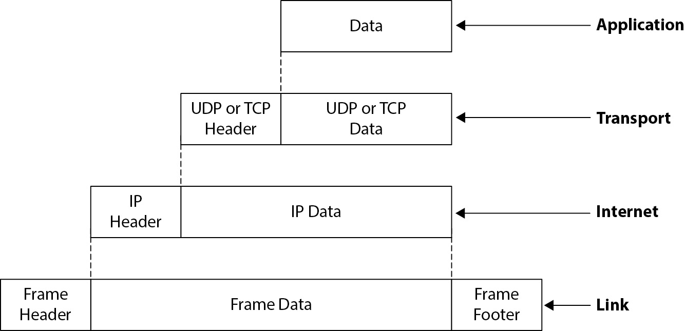
Figure 5-11 Encapsulation in the TCP/IP network model
The layers of the TCP/IP model, from bottom to top, are
• Link
• Internet
• Transport
• Application
These layers are discussed in detail in this section.
One of the primary purposes of the layered model (in both the OSI and TCP/IP models) is to permit abstraction. This means that each layer need be concerned only with its own delivery characteristics, while permitting other layers to manage their own matters. For instance, order of delivery is managed by the transport layer; at the Internet and link layers, order of delivery is irrelevant. Also, the link layer is concerned with just getting a message from one station to another and with collisions and the basic integrity of the message as it is transported from one device to another; but the link layer has no concept of a logical connection or with order of delivery, which are addressed by higher layers.
TCP/IP Link Layer The link layer is the lowest layer in the TCP/IP model. Its purpose is the delivery of messages (usually called frames) from one station to another on a local network. Being the lowest layer of the TCP/IP model, the link layer provides services to the transport layer.
The link layer is the physical layer of the network and is usually implemented in the form of hardware network adaptors. TCP/IP can be implemented on top of any viable physical medium that has the capacity to transmit frames from one station to another. Examples of physical media used for TCP/IP include those from standards such as Ethernet, ATM, USB, Wi-Fi, Bluetooth, GPRS (General Packet Radio Service), DSL, ISDN (Integrated Services Digital Network), and fiber optics.
The link layer is only concerned with the delivery of messages from one station to another on a local network. At this layer, there is no concept of neighboring networks or of routing; these are handled at higher layers in the model.
TCP/IP Internet Layer The Internet layer of the TCP/IP model is the foundation layer of TCP/IP. The purpose of this layer is the delivery of messages (packets) from one station to another on the same network or on different networks. The Internet layer receives services from the link layer and provides services to the transport layer.
At this layer, the delivery of messages from one station to another is not guaranteed. Instead, the Internet layer makes only a best effort to deliver messages. The Internet layer also does not concern itself with the sequence of delivery of messages. Concerns such as these are addressed at the transport layer.
The primary protocol that has been implemented in the Internet layer is the Internet Protocol. IP is the building block for nearly all other protocols and message types in TCP/IP. One other protocol is common in the Internet layer: ICMP (Internet Control Message Protocol), a diagnostic protocol that is used to send error messages and other diagnostic messages over networks.
At the Internet layer, there are two types of devices: hosts and routers. Hosts are computers that could be functioning as servers or workstations. They communicate by creating messages that they send on the network. Routers are computers that forward packets from one network to another. In the early Internet, routers really were computers like others, with some additional configurations that they used to forward packets between networks.
The relationship between hosts and routers is depicted in Figure 5-12.

Figure 5-12 Hosts and routers at the Internet layer
TCP/IP Transport Layer The transport layer in the TCP/IP model consists of two main packet transport protocols, TCP and UDP, as well as a few other protocols that were developed after the initial design of TCP/IP. The transport layer receives services from the Internet layer and provides services to the application layer.
Several features are available at the transport layer for packet delivery, including
• Reliable delivery This involves two characteristics: integrity of the packet contents and guaranteed delivery. TCP includes these two features that ensure confirmation that a packet sent from one station will be delivered to its destination and that the contents of the packet will not be altered along the way.
• Connection orientation This involves the establishment of a persistent logical “connection” between two stations. This is particularly useful when a station is communicating on many simultaneous “conversations” from one or more source stations. When a connection is established, the requesting system communicates on an arbitrary source port, to the destination system on standard ports (such as HTTP port 80, DNS port 53, and so on). The two stations will negotiate and agree on arbitrary high-numbered ports (channels) that will make each established connection unique.
• Sequence of delivery The sequence of delivery of packets can be guaranteed to match the order in which they were sent. This is implemented through the use of sequence numbers, which are used by the receiving system to deliver packets in the correct order to the receiving process.
• Flow control This means that the delivery of packets from one station to another will not overrun the destination station. For example, the transfer of a large file from a faster system to a slower system could overrun the slower system, unless the latter has a way to pause the transfer (flow control) periodically so that it can keep up with the inbound messages.
• Port number A message on one station may be sent to a specific port number on a destination station. A port number essentially signifies the type of message that is being sent. A “listener” program can be set up on a destination system to listen on a preassigned port and then process messages received on that port number. The primary advantage of port numbers is that a destination system does not need to examine the contents of a message to discern its type; instead, the port number defines the purpose. There are many standard port numbers established, including 23 = Telnet, 25 = e-mail, 53 = Domain Name System, 80 = HTTP, and so on.
Note that not all transport layer protocols utilize all of these features. For instance, UDP utilizes flow control but none of the other features listed.
TCP/IP Application Layer The application layer is the topmost layer of the TCP/IP model. This layer interfaces directly with applications and application services. The application layer receives services from the transport layer and may communicate directly with end users.
Application layer protocols include DNS, SNMP, DHCP, NTP, SMTP, NNTP, HTTP, HTTPS, NFS, FTP, and Telnet. There are many more.
The TCP/IP and OSI Models The TCP/IP model was not designed to conform to the seven-layer OSI network model. However, the models are similar in their use of encapsulation and abstraction, and some layers between the two models are similar. Figure 5-13 shows the TCP/IP and OSI models side by side and how the layers in one model correspond to the other.
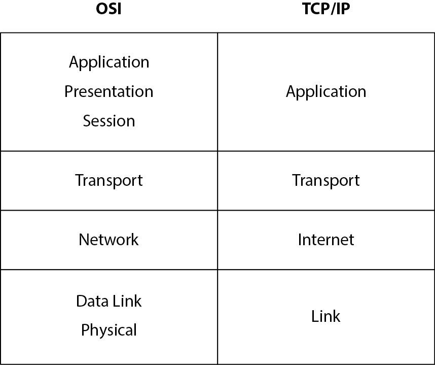
Figure 5-13 The TCP/IP and OSI network models side by side

EXAM TIP Mapping TCP/IP and OSI models to each other has no practical purpose except to understand their similarities and differences. There is no unanimous agreement on the mapping of the models. It is easy to argue for some small differences in the way that they are conjoined.
Network Technologies
Many network technologies have been developed over the past several decades. Some, such as Ethernet, DSL, and TCP/IP, are found practically everywhere, while other technologies, such as ISDN, Frame Relay, and AppleTalk, have had shorter lifespans.
The IS auditor needs to be familiar with network technologies, architectures, protocols, and media so that he or she may examine an organization’s network architecture and operation. The following sections describe network technologies at a level of detail that should be sufficient for most auditing needs:
• Local Area Networks This section discusses LAN topologies, cabling, and transport protocols (including Ethernet, ATM, Token Ring, USB, and FDDI).
• Wide Area Networks This section discusses WANs, including transport protocols MPLS, SONET, T-Carrier, Frame Relay, and ISDN.
• Wireless Networks This section discusses wireless network standards Wi-Fi, Bluetooth, Wireless USB, NFC, and IrDA.
• TCP/IP Protocols and Devices This section discusses TCP/IP protocols in the link layer, Internet layer, transport layer, and application layer.
• The Global Internet This section discusses global Internet addressing, DNS, routing, and applications.
• Network Management This section discusses the business function, plus the tools and protocols used to manage networks.
• Networked Applications This section discusses the techniques used to build network-based applications.
Local Area Networks
Local area networks exist within a relatively small area, such as a floor in a building, a lab, a storefront, an office, or a residence. Because of electrical signaling limitations, a LAN is usually several hundred feet in length or less.
Physical Network Topology Wired LANs are transported over network cabling that runs throughout a building. Network cabling is set up in one of three physical topologies:
• Star A separate cable is run from a central location to each computer. This is the way that most networks are wired today. The central location might be a wiring closet or a computer room, where all of the cables from each computer would converge at one location and be connected to network equipment such as a switch or hub.
• Ring Cabling runs from one computer to the next. Early Token Ring and Ethernet networks were often wired this way. Where the network cable was attached to a computer, a “T” connector was used: one part connected to the computer itself, and the other two connectors were attached to the network cabling.
• Bus A central cable, with connectors along its length that facilitate “branch” cables connected to individual computers. Like the ring topology, this was used in early networks but is seldom used today.
These three topologies are depicted in Figure 5-14.
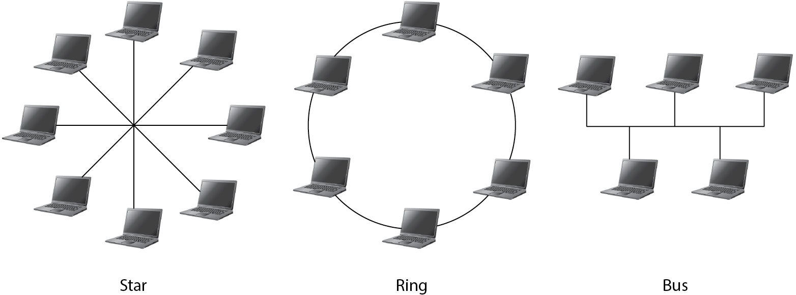
Figure 5-14 Network physical topologies: star, ring, and bus
Note that the logical function and physical topology of a network may vary. For instance, a Token Ring network may resemble a physical star (with all stations connected to a central device), but it will function logically as a ring. An Ethernet network functions as a bus, but it may be wired as a star, bus, or ring, depending on the type of cabling used (and, as indicated earlier, star topology is prevalent). The point is that logical function and physical topology often differ from each other.
Cabling Types Several types of cables have been used in LANs over the past several decades. This section will focus on the types in use today but will mention those that have been used in the past, which may still be in use in some organizations.
Twisted-Pair Cable Twisted-pair cabling is a thin cable that contains four pairs of insulated copper conductors, all surrounded by a protective jacket. Several varieties of twisted-pair cabling are suitable for various physical environments and provide various network bandwidth capabilities.
Because network transmissions can be subject to interference, network cabling may include shielding that protects the conductors from interference. Some of these types are
• Shielded twisted pair (U/FTP or STP) This type of cable includes a thin metal shield that protects each pair of conductors from electromagnetic interference (EMI), making it more resistant to interference.
• Screened unshielded twisted pair (S/UTP) Also known as foiled twisted pair (FTP), this type of cable has a thin metal shield that protects the conductors from EMI.
• Screened shielded twisted pair (S/STP or S/FTP) This type of cable includes a thin layer of metal shielding surrounding each twisted pair of conductors, plus an outer shield that protects all of the conductors together. This is all covered by a protective jacket.
• Unshielded twisted pair (UTP) This type of cable has no shielding and consists only of the four pairs of twisted conductors and the outer protective jacket.
The abbreviations for twisted-pair cable have recently changed in compliance with international standard ISO/IEC 11801, “Information technology—Generic cabling for customer premises.” The new standard takes the form X/YTP, where X denotes whether the entire cable has shielding, and Y indicates whether individual pairs in the cable are shielded. Table 5-1 shows the old and new names and their meanings. The old names are likely going to be in common use for many years, as office buildings and residences around the world are wired with twisted-pair cabling that is labeled with the old names; this wiring will likely last for decades in many locations.

Table 5-1 Old and New Twisted-Pair Cabling Abbreviations and Meaning
Twisted-pair network cabling is also available with different capacity ratings to meet various bandwidth requirements. The common ratings include
• Category 3 Known as “Cat-3,” this is the oldest still-recognized twisted-pair cabling standard, capable of transporting 10Mbit Ethernet up to 100 meters (328 ft.). The 100BASE-T4 standard permitted up to 100Mbit Ethernet over Cat-3 cable by using all four pairs of conductors. Cat-3 cable is no longer installed but is still found in older networks.
• Category 5 Cat-5 cabling grade has been in common use since the mid-1990s and is suitable for 10Mbit, 100Mbit, and 1000Mbit (1Gbit) Ethernet over distances up to 100 meters (328 ft.). Cat-5 cable is typically made from 24-gauge copper wire with three twists per inch. A newer grade, Category 5e, has better performance for Gigabit Ethernet networks.
• Category 6 This is the cabling standard for Gigabit Ethernet networks. Cat-6 cabling greatly resembles Cat-5 cabling, but Cat-6 has more stringent specifications for crosstalk and noise. Cat-6 cable is typically made from 23-gauge copper. Cat-6 cabling is “backward compatible” with Cat-5 and 5e cabling, which means that Cat-6 cables can be used for 10Mbit and 100Mbit Ethernet networks as well as 1000Mbit (1Gbit).
• Category 7 This cable standard has been developed to permit 10Gbit Ethernet over 100 meters of cabling. Cat-7 cabling is almost always made from S/FTP cabling to provide maximum resistance to EMI. A newer grade, Category 7a, is designed to have telephone, cable TV, and 1GB networking in the same cable. This newer grade is still under development.
• Category 8 This is a new cable standard designed for high-speed networking over short distances, intended for use in data centers.
Twisted-pair cable ratings are usually printed on the outer jacket of the cable. Figure 5-15 shows a short length of Category 5 cable with the rating and other information stamped on it.
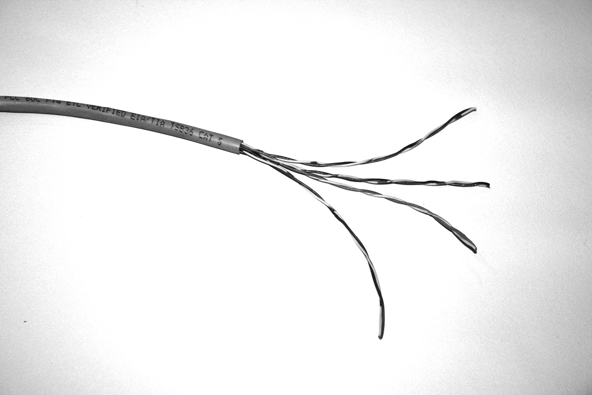
Figure 5-15 Category 5 twisted-pair cable (Image courtesy of Rebecca Steele)
Fiber Optic Cable Fiber optic cable is the transmission medium for fiber optic communications, which is the method of transmitting information using pulses of light instead of electric signals through metal cabling. The advantages of fiber optic cable are its much higher bandwidth, lower loss, and compact size. Because communications over fiber optic cable are based on light instead of electric current, they are immune from EMI.
In LANs, multimode-type fiber optic cable can carry signals up to 10 Gbit/sec up to 600 meters (and distances up to a few kilometers at lower bandwidths), sufficient for interconnecting buildings in a campus-type environment. For longer distances, single-mode–type fiber optic cable is used, usually by telecommunications carriers for interconnecting cities for voice and data communications.
Compared to twisted-pair and other network cable types, fiber optic cable is relatively fragile and must be treated with care. It can never be pinched, bent, or twisted—doing so will break the internal fibers. For this reason, fiber optic cabling is usually limited to data centers requiring high bandwidths between systems, where network engineers will carefully route fiber optic cabling from device to device, using guides and channels that will prevent the cable from being damaged. But the advantage of fiber optic cabling is its high capacity and freedom from EMI.
Figures 5-16 and 5-17 show fiber optic cable and connectors.

Figure 5-16 Fiber optic cable with its connector removed to reveal its interior (Image courtesy of Harout S. Hedeshian)

Figure 5-17 Connectors link fiber optic cable to network equipment. (Image courtesy of Stephane Tsacas)
Other Types of Network Cable Twisted-pair and fiber optic cable are the dominant LAN cable types. However, older types of cable have been used and are still found in many installations, including
• Coaxial Coaxial cable consists of a solid inner conductor that is surrounded by an insulating jacket, surrounded by a metallic shield. A plastic jacket protects the shield. Coaxial cables were used in early Ethernet networks with cable types such as 10BASE5 and 10BASE2. Twist-lock or threaded connectors were used to connect coaxial cable to computers or network devices. This is fundamentally the type of cable also used for “TV cable.” A typical coaxial cable is shown in Figure 5-18.

Figure 5-18 Coaxial cable (Image courtesy of Fdominec)
• Serial Point-to-point network connections can be established over USB or RS-232 serial cables. In the case of serial lines, in the 1980s, many organizations used central computers and user terminals that communicated over RS-232 serial cabling. At that time, these existing cable plants made the adoption of SLIP (Serial Line Internet Protocol) popular for connecting workstations and minicomputers to central computers using existing cabling. SLIP is all but obsolete now, displaced by USB.
Network Transport Protocols Many protocols, or standards, have been developed to facilitate data communications over network cabling. Ethernet, ATM, Token Ring, USB, and FDDI protocols are described in detail in the following sections.
Ethernet Ethernet is the dominant standard used in LANs. It uses a frame-based protocol, which means that data transmitted over an Ethernet-based network is placed into a “frame” that has places for source and destination addresses as well as contents.
Shared Medium Ethernet is a “broadcast” or “shared medium” type of protocol. This means that a frame that is sent from one station on a network to another station may be physically received by all stations that are connected to the network medium. When each station receives the frame, the station will examine the destination address of the frame to determine whether the frame is intended for that or another station. If the frame is destined for another station, the station will simply ignore the frame and do nothing. The destination station will accept the frame and deliver it to the operating system for processing.
Collision Detection Ethernet networks are asynchronous—a station that needs to transmit a frame may do so at any time. However, Ethernet also employs a “collision detection” mechanism whereby a station that wants to broadcast a frame will begin transmitting and also listen to the network to see if any other stations are transmitting at the same time. If another station is transmitting, the station that wants to transmit will “back off” and wait for a short interval and then try again (in a 10Mbit Ethernet, the station will wait for 9.6 microseconds). If a collision (two stations transmitting at the same time) does occur, both transmitting stations will stop, wait a short interval (the length of the interval is based on a randomly generated number), and then try again. The use of a random number as a part of the “back-off” algorithm ensures that each station has a statistically equal chance to transmit its frames on the network. This is essential for large networks with numerous stations.
Ethernet Addressing On an Ethernet network, each station on the network has a unique address called a Media Access Control (MAC) address, expressed as a six-byte hexadecimal value. A typical address is displayed in a notation separated by colons or dashes, such as F0:E3:67:AB:98:02.
The Ethernet standard dictates that no two devices in the entire world will have the same MAC address; this is established through the issuance of ranges of MAC addresses that are allocated to each manufacturer of Ethernet devices. Typically, each manufacturer will be issued a range, which consists of the first three bytes of the MAC address; the manufacturer will then assign consecutive values for the last three bytes to each device that it produces.
For example, suppose a company is issued the value A0-66-01 (called its Organizationally Unique Identifier, or OUI). The devices that the company produces will have that value as the first three bytes of its MAC address and assign three additional bytes to each device that it produces, giving addresses such as A0-66-01-FF-01-01, A0-66-01-FF-01-02, A0-66-01-FF-01-03, and so on. This will guarantee that no two devices in the world will have the same address.
Ethernet Frame Format An Ethernet frame consists of a header segment, a data segment, and a checksum. The header segment contains the destination MAC address, the source MAC address, and a two-byte Ethernet type field. The data segment ranges from 46 to 1,500 bytes in length—the maximum for any particular network is known as the maximum transmission unit (MTU). The checksum field is four bytes in length and is a CRC (cyclic redundancy check) checksum of the entire frame. An Ethernet frame is shown in Figure 5-19.
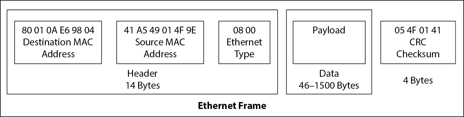
Figure 5-19 An Ethernet frame consists of a header, data, and checksum
Network Devices Network devices must not only facilitate the transmission of frames on Ethernet networks, but they must support all other network standards as well. These devices include
• Network adaptor A network adaptor, commonly known as a network interface card (NIC), is a device that is directly connected to a computer’s bus and contains one or more connectors to which an Ethernet network cable may be connected. Often, a computer’s NIC is integrated with the computer’s motherboard, but a NIC may also be a separate circuit card that is plugged into a bus connector.
• Hub Organizations came to realize that ring and bus topology networks were problematic with regard to cable failures. This gave rise to the star topology as a preferred network architecture, because a cable problem would affect only one station instead of many or all stations. A multiport repeater would be used to connect all of the devices to the network. Over time, this device became known as a hub. Like repeaters, Ethernet hubs propagate packets to all stations on the network.
• Gateway A gateway is a device that acts as a protocol converter or performs some other type of transformation of messages.
• Repeater A repeater is a device that receives and retransmits the signal on an Ethernet network. Repeaters are useful for situations in which cable lengths exceed 100 meters, or to interconnect two or more Ethernet networks. A disadvantage of repeaters is that they propagate collisions, errors, and other network anomalies onto all parts of the network. Repeaters as stand-alone devices are seldom used in Ethernet networks today; more modern devices have absorbed their functions.
• Bridge A bridge is a device used to interconnect Ethernet networks. For example, an organization may have an Ethernet network on each floor of a multistory building; a bridge can be used to interconnect each of the separate Ethernet segments. A bridge is similar to a repeater, except that a bridge does not propagate errors such as collisions, but instead propagates only well-formed packets. Bridges also, as stand-alone devices, are seldom seen in today’s Ethernet networks.
• Switch An Ethernet switch is similar to a hub, but with one important difference: a switch will listen to traffic and learn the MAC address(es) associated with each port (connector) and will send packets only to destination ports. The result is potentially greater network throughput, because each station on the network will be receiving only the frames that are specifically addressed to it. When only one station is connected to each port on an Ethernet switch, theoretically, collisions will never occur. Switches are the dominant method for contemporary networks.
Devices such as routers, layer 3 switches, layer 4 switches, and layer 4-7 switches are discussed in the section “TCP/IP Protocols and Devices,” later this chapter.
ATM ATM, or Asynchronous Transfer Mode, is a link-layer network protocol developed in the 1980s in response to the need to unify telecommunications and computer networks. ATM has been a dominant protocol in the core networks of telecommunications carriers, although IP is becoming more dominant.
Messages (called cells) on an ATM network are transmitted in synchronization with a network-based time clock. Stations on an Ethernet, on the other hand, transmit as needed, provided the network is quiet at the moment.
ATM cells are fixed at a length of 53 bytes (5-byte header and 48-byte payload). This small frame size improves performance by reducing jitter, which is a key characteristic of networks that are carrying streaming media such as broadcast television, VoIP, or video.
ATM is a connection-oriented link-layer protocol. This means that two devices on an ATM network that want to communicate with each other will establish a connection through a virtual circuit. A connection also establishes a Quality of Service (QoS) setting for the connection that defines the priority and sensitivity of the connection.
Cells that are transmitted from one station to another are transported through one or more ATM switches. The path that a cell takes is established at the time that the virtual circuit is established. An ATM switch is used even when two stations on the same LAN are communicating with each other.
Like Ethernet, ATM can be used to transport TCP/IP messages. TCP/IP packets that are larger than 48 bytes in length are transmitted over ATM in pieces and reassembled at the destination.
Token Ring Token Ring is a LAN protocol that was developed by IBM in the 1980s. Historically, Token Ring was prevalent in organizations that had IBM mainframe or midrange computer systems. However, as TCP/IP and Ethernet grew in popularity, Token Ring declined and it is rarely found today.
Token Ring networks operate through the passage of a three-byte token frame from station to station on the network. If a station needs to send information to another station on the network, it must first receive the token; then it can place a frame on the network that includes the token and the message for the destination station. When the token frame reaches the destination station, the destination station will remove the message from the token frame and then pass an empty token (or a frame containing the token and a message for another station) to the next station on the network.
The principal Token Ring device is the multistation access unit, or MAU. A MAU is a device that contains several Token Ring cable connectors and connects network cables from the MAU to each station on the network. A typical MAU contains as many as eight connectors; if a Token Ring network is to contain more than eight stations, MAUs can be connected together using their ring in/ring out connectors. Figure 5-20 shows small and large Token Ring networks.
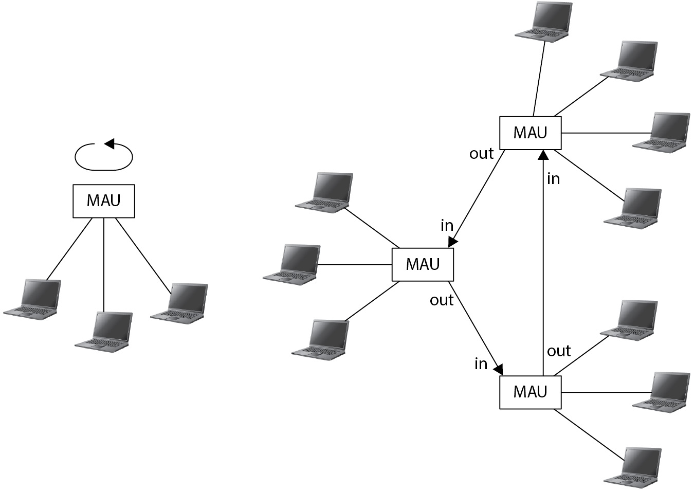
Figure 5-20 Token Ring network topologies
The design of Token Ring technology makes collisions impossible, since no station can transmit unless it possesses the token. A disadvantage of this design occurs if the station with the token encounters a malfunction that causes it not to propagate the token. This results in a momentary pause until the network goes into a recovery mode and regenerates a token.
Universal Serial Bus Universal Serial Bus (USB) is not typically considered a network technology, but rather a workstation bus technology. This is primarily because USB is used to connect peripherals such as mice, keyboards, storage devices, printers, scanners, cameras, microphones, and network adaptors. However, the USB specification indeed contains full networking capabilities, which makes use of those small USB hubs possible.
USB data rates are shown in Table 5-2.
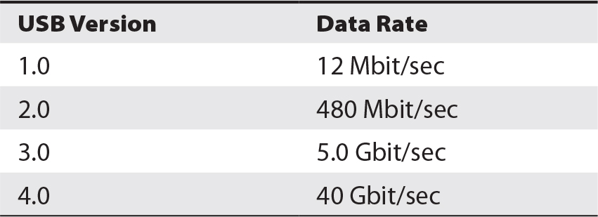
Table 5-2 USB Data Rates
Cable length for USB is restricted to 5 meters. The maximum number of devices on a USB network is 127.
One of the valuable characteristics of USB technology is the ability to “hot plug” devices. This means that USB devices can be connected and disconnected without the need to power down the workstation they are connected to. This is achieved primarily through the design specification for devices and device drivers that tolerate plugging and unplugging. This does not mean, however, that all types of USB devices may be plugged and unplugged at will. USB mass storage devices, for instance, should be logically “dismounted” to ensure the integrity of the file system on the device.
FDDI Fiber Distributed Data Interface (FDDI) is a LAN technology whose range can extend up to 200 kilometers over optical fiber. FDDI is a “dual ring” technology that utilizes redundant network cabling and counter-rotating tokens, which together make FDDI highly resilient. Each ring has a 100 Mbit/sec data rate, making the entire network capable of 200 Mbit/sec.
FDDI has been largely superseded by 100 Mbit/sec and 1 Gbit/sec Ethernet and is no longer common in commercial networks.
Wide Area Networks
Wide area networks (WANs) can extend for miles to thousands of miles between stations. The term WAN is generally used in two ways: to connote an organization’s entire regional or global data network and as the label for the long-distance network connections used to join individual networks together. In the second usage, the terms “WAN link” and “WAN connection” are used.
Wide Area Transmission Modes Before we discuss specific WAN protocols, it is important that you understand the basics of message transmission techniques used in WANs.
The basic problem of wide area communications is the need to route communications efficiently from many different endpoints to many destinations, without constructing dedicated connections between all possible communication sources and destinations. Instead, some scheme for sharing a common communication medium is needed. These methods are
• Circuit-switched Here, a dedicated, end-to-end communications channel is established that lasts for the duration of a connection. The best-known example of circuit-switched technology is the old public-switched telephone network, where a telephone call from one telephone to another occupied a dedicated circuit that was assigned at the onset of the call and used until the call was finished.
• Packet-switched Communications between endpoints takes place over a stream of packets, which are routed through switches until they reach their destination. Frame Relay and the TCP/IP Internet are good examples of packet-switched networks. And while landline telephone calls still have the appearance of being circuit-switched, telephone conversations are actually converted into packets for transmission through the core of a digital telecommunications network.
• Message-switched Each message is switched to its destination when a communications path is available. An example of message switching is the transmission of individual e-mail messages between servers on the Internet.
• Virtual circuit A logical communications channel is established between two endpoints on a packet-switched network. This communications channel may be known as a permanent virtual circuit (PVC) or a switched virtual circuit (SVC). Virtual circuits are used in ATM and Frame Relay networks. VPNs can also be thought of as virtual circuits.
Wide Area Network Protocols This section describes several well-known protocols used in WANs.
MPLS Multiprotocol Label Switching (MPLS) is a variable-length, packet-switched network technology. In an MPLS network, each packet has one or more labels affixed to it that contain information that helps MPLS routers to make packet-forwarding decisions, without having to examine the contents of the packet itself (for an IP address, for instance).
MPLS can be used to carry many types of traffic, including Ethernet, ATM, SONET, and IP. It is often used to trunk voice and data networks over WAN connections between business locations in an enterprise network. One of the strengths of MPLS is its QoS (quality of service) properties, which facilitate the rapid transfer of packets using time-sensitive protocols such as VoIP and H.323.
MPLS employs two types of devices: label edge routers (LERs) and label switch routers (LSRs). Label edge routers are used at the boundaries of an MPLS network; LERs push a label onto incoming packets that enter the network. LSRs make packet-forwarding decisions based upon the value of the label. When a packet leaves the MPLS network, another LER pops the label off the packet and forwards it out of the MPLS network.
SONET Synchronous Optical Networking (SONET) is a class of telecommunications network transport technologies transmitted over fiber optic networks. It is a multiplexed network technology that can be used to transport voice and data communications at very high speeds over long distances.
SONET networks are almost exclusively built and operated by telecommunications network providers that sell voice and data connectivity services to businesses. Often, the endpoint equipment for SONET networks provides connectivity using a native technology such as MPLS, Ethernet, or T-1.
Telecommunications service providers often encapsulate older services, such as DS0, DS-1, T-1, and Frame Relay, over SONET networks.
The data rates available in SONET networks are shown in Table 5-3. Rates are expressed using the term Optical Carrier Level, abbreviated OC.

Table 5-3 SONET OC Levels
T-Carrier The term T-Carrier refers to a class of multiplexed telecommunications carrier network technologies developed to transport voice and data communications over long distances using copper cabling.
The basic service in T-Carrier technology is known as DS-0, which is used to transport a single voice or data circuit. The data rate for a DS-0 is 64 Kbit/sec. Another basic T-Carrier service is the DS-1, also known as T-1. DS-1 contains 24 channels, each a DS-0. The total speed of a DS-1 is 1,544 Kbit/sec. There are additional services, all of which are shown, together with their respective data rates and channels, in Table 5-4. These services are unique to North America.
Table 5-4 T-Carrier Data Rates and Channels in North America
In Europe, T-Carrier circuits are known instead as E-1 and E-3, which multiplex 32 and 512 64 Kbit/sec circuits, respectively. The European E-Carrier standards are based on multiples of 32 circuits, whereas North American standards are based on multiples of 24 circuits. Otherwise, there isn’t much practical difference between them. E-Carrier services are shown in Table 5-5.
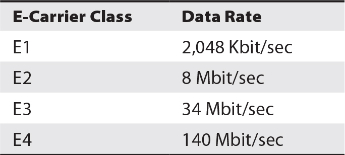
Table 5-5 E-Carrier Services
T-Carrier and E-Carrier protocols are synchronous, which means that packets transported on a T-Carrier or E-Carrier network are transmitted according to the pulses of a centralized clock that is usually controlled by the telecommunications carrier. This is contrasted with Ethernet, which is asynchronous, meaning a station on an Ethernet may transmit a frame at any time of its choosing (provided the network is not busy at that exact moment).
Organizations that use a T-Carrier or E-Carrier service to carry data can utilize individual DS-0 channels (which are the same speed as a dial-up connection) or an entire T-1 (or E-1) circuit without multiplexing. This enables use of the entire 1,544 Kbit/sec (T-1) or 2,048 Kbit/sec (E-1) as a single resource.
Frame Relay Frame Relay is a carrier-based, packet-switched network technology. It is most often used to connect remote data networks to a centralized network; for example, a retail store chain might use Frame Relay to connect each of its retail store LANs to the corporate LAN.
Frame Relay is often more economical than dedicated DS-0 or DS-1/T-1 circuits. By their nature, Frame Relay backbone networks are shared, in the sense that they transport packets for many customers.
Connections between locations using Frame Relay are made via a permanent virtual circuit (PVC), which is not unlike a VPN, except that the payload is not encrypted. For purposes of security and privacy, PVCs are generally considered private, like a T-1 circuit.
Frame Relay has all but superseded the older X.25 services. MPLS is rapidly overtaking Frame Relay.
ISDN ISDN, or Integrated Services Digital Network, is best described as a digital version of the public-switched telephone network. In many regions of the United States, ISDN was the first “high-speed” Internet access available for residential and small business subscribers.
A subscriber with ISDN service will have a digital modem with one connection to a digital ISDN voice telephone and one connection (typically Ethernet) to a computer. The speed of the computer connection in this configuration is 64 Kbits/sec. Alternatively, the ISDN modem could be configured in a “bonded” state with no voice telephone and only a computer connection at 128 Kbits/sec. Both of these configurations use a BRI (basic rate interface) type of connection.
Higher speeds are also available, up to 1,544 Kbits/sec, and are known as a PRI (primary rate interface) type of connection.
ISDN utilizes a separate, but similar, environment where an ISDN modem “dials” a phone number, similar to dial-up Internet service.
Wide Area Network Devices This section describes devices used to connect WAN components to each other and to an organization’s internal network.
Modem A modulator-demodulator unit, also known as a modem, is a device used to connect a telecommunications carrier network to a computer or a LAN. Early modems consisted of an analog telephone connector for connecting to the public telephone network and a serial port for connecting to a computer. Later versions connect to ISDN, cable, and DSL networks and include an Ethernet port for connecting to a single computer or a LAN.
Multiplexor A multiplexor connects several separate signals and combines them into a single data stream. There are four basic types of multiplexing:
• Time division Separate signals are combined into a pattern, where each individual signal occupies a separate dedicated timeslot.
• Asynchronous time division multiplexing Separate signals are allocated into timeslots of varying sizes depending on need.
• Frequency division multiplexing Separate signals are combined into a single stream, where each separate signal occupies a nonoverlapping frequency.
• Statistical multiplexing Separate signals are inserted into available timeslots. This is different from time division multiplexing, where input signals are assigned to timeslots. In statistical multiplexing, input signals are dynamically assigned to available timeslots.
Channel Service Unit/Digital Service Unit Also known as a CSU/DSU, this device is used to connect a telecommunications circuit (typically, a T-1 line) to a device such as a router. A CSU/DSU is essentially a modem for T-1 and similar telecomm technologies.
WAN Switch WAN switch is a general term that encompasses several types of WAN switching devices, including ATM switches, Frame Relay switches, MPLS switches, and ISDN switches. See the respective sections on these technologies earlier in this chapter.
Router A router is a device used to connect two or more logical local (occupying the same subnet) networks together. In the context of WANs, a router would be used to connect two or more WANs to each other.
See also the discussion of routers in the “TCP/IP Protocols and Devices” section, later in this chapter.
Wireless Networks
Several types of wireless technologies are available to organizations that want to implement data communications without constructing or maintaining a wiring plant. Furthermore, wireless networks permit devices to move from place to place, even outside of buildings, facilitating highly flexible and convenient means for high-speed communications.
The technologies discussed in this section are the type that an organization would set up on its own, without any services required from a telecommunications service provider.
Wi-Fi Wi-Fi describes several similar standards developed around the IEEE 802.11i/a/b/n/ac/ad/af/ah/aj/aq/ax/ay/n standards. Wi-Fi, or WLAN, permits computers to communicate with each other wirelessly at high speeds over moderate distances from each other. The term “Wi-Fi” is a trademark of the Wi-Fi Alliance for certifying products as compatible with IEEE 802.11 standards. The generic term describing networks based on IEEE 802.11 standards is wireless LAN, or WLAN, although this term is not often used.
Wi-Fi Standards The various Wi-Fi standards are outlined in Table 5-6.
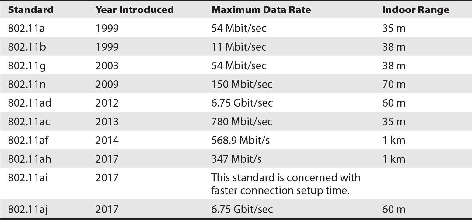
Table 5-6 Comparison of Wi-Fi Standards
Wi-Fi Security Wi-Fi networks can be configured with several security features that protect the privacy as well as the availability of the Wi-Fi network. Available features include
• Authentication Individual stations that want to connect with a Wi-Fi network can be required to provide an encryption key. Furthermore, the user may be required to provide a user ID and password. Without this information, a station is unable to connect to the Wi-Fi network and communicate with it. Wi-Fi access points can contain a list of user IDs and passwords, or they can be configured to utilize a network-based authentication service such as RADIUS, LDAP, or Active Directory. Use of the latter generally makes more sense for organizations that want to centralize user authentication information; this also makes access simpler for employees, who do not need to remember yet another user ID and password.
• Access control A Wi-Fi network can be configured to permit only stations with known MAC addresses or specific digital certificates to connect to it. Any station without a permitted address or certificate will not be able to connect.
• Encryption A Wi-Fi network can use encryption to protect traffic from interception through over-the-air eavesdropping. It can encrypt with the WEP (Wired Equivalent Privacy; now deprecated and should not be used), WPA (Wi-Fi Protected Access), WPA2, or WPA3 method. A Wi-Fi network can also be configured not to use encryption, in which case another station may be able to eavesdrop on any communications on the wireless network. When a Wi-Fi network uses encryption, only the airlink communications are encrypted; network traffic from the Wi-Fi access point to other networks will not be encrypted.
• Network identifier A Wi-Fi access point is configured with a service set identifier (SSID) that identifies the network. For organizations that provide network access only for their own personnel, it is recommended that the SSID not be set to a value that makes the ownership or identity of the access point obvious. Using a company name, for instance, is not a good idea. Instead, a word—even a random set of characters—that does not relate to the organization’s identity should be used. The reason for this is that the SSID will not itself identify the owner of the network, which could, in some circumstances, invite outsiders to attempt to access it. An exception to this is a “public hotspot” used to provide free network access, where the SSID will clearly identify the establishment providing access.
• Broadcast A Wi-Fi access point can be configured to broadcast its SSID, making it easier for users to discover and connect to the network. However, broadcasting SSIDs also alerts outsiders to the presence of the network, which can compromise network security by encouraging someone to attempt to connect to it. However, turning off the SSID broadcast does not make the network absolutely secure: a determined intruder can obtain tools that will enable him or her to discover the presence of a Wi-Fi network that does not broadcast its SSID.
• Signal strength The transmit signal strength of a Wi-Fi access point can be configured so that radio signals from the access point do not significantly exceed the service area. Often, signal strength of access points will be set to maximum, which provides persons outside the physical premises with a strong signal. Instead, transmit signal strength should be turned down so that as small a signal as possible leaves the physical premises. This is a challenge in shared-space office buildings, however, and thus cannot be used as a Wi-Fi network’s only security control.

CAUTION Because a Wi-Fi network utilizes radio signals, an untrusted outsider is able to intercept those signals, which could provide enough information for that outsider to penetrate the network. It is for this reason that all of the controls discussed in this section should be utilized to provide an effective defense-in-depth security protection.
WiMAX WiMAX (Worldwide Interoperability for Microwave Access) is a set of wireless telecommunications protocols that provides data throughput from 30 Mbit/sec to 1 Gbit/sec. WiMAX is an implementation of the IEEE 802.16 standard.
WiMAX networks were in service in the 2000s but have been largely discontinued in favor of LTE.
LTE LTE (Long Term Evolution) is a telecommunications standard for wireless voice and data communications for smartphones, mobile devices, and wireless broadband modems. LTE is a shared-medium technology that provides data rates up to 300 Mbit/sec.
Bluetooth Bluetooth is a short-range airlink standard for data communications between computer peripherals and low power consumption devices. Designed as a replacement for short-range cabling, Bluetooth also provides security via authentication and encryption.
Applications using Bluetooth include
• Mobile phone earsets
• In-car audio for smartphones
• Data transfer between smartphones and computers
• Music player headphones
• Computer mice, keyboards, and other low-power and low-speed peripherals
• Printers and scanners
Bluetooth is a lower-power standard, which supports the use of very small devices, such as mobile phone earsets. And yet, a new standard, Bluetooth Low Energy (BLE), uses far less power for devices such as security tokens. The Bluetooth standard includes one-time authentication of devices using a process called pairing. Communications over Bluetooth can also be encrypted so that any eavesdropping is made ineffective. Data rates range from 1 to 24 Mbit/sec.
WUSB Wireless USB (WUSB) is a short-range, high-bandwidth wireless protocol used for personal area networks (PANs). Data rates range from 110 to 480 Mbit/sec. WUSB is typically used to connect computer peripherals that would otherwise be connected with cables.
WUSB can be thought of as a competitor to Bluetooth, and due to Bluetooth’s success, WUSB is not widely used.
NFC Near-Field Communications (NFC) is a standard of extremely short-distance radio frequencies that are commonly used for merchant payment applications. The typical maximum range for NFC is 10 centimeters (4 in.).
NFC supports two types of communications: active-active and active-passive. In active-active mode, the base station and the wireless node electronically transmit messages over the NFC airlink. In active-passive mode, the wireless node has no active power supply and instead behaves more like an RFID (radio frequency identification) card. Throughput rates range from 106 to 848 Kbit/sec.
Common applications of NFC include merchant payments using a mobile phone or credit card–sized card, and advanced building access control systems.
IrDA IrDA (Infrared Data Association) is an organization that has developed technical standards for point-to-point data communications using infrared light. IrDA has been used for communications between devices such as laptop computers, PDAs, and printers.
IrDA is not considered a secure protocol: there is no authentication or encryption of IrDA-based communications.
Bluetooth and USB have largely replaced IrDA, and few IrDA-capable devices are now sold.
TCP/IP Protocols and Devices
TCP/IP, the technology that the Internet is built upon, contains numerous protocols. This section discusses many of the well-known protocols, layer by layer. First, link layer protocols are discussed, followed by Internet layer protocols, then transport layer protocols, and finally application layer protocols. This is followed by a discussion of network devices that are used to build TCP/IP networks.
Link Layer Protocols The link layer (sometimes referred to as the network access layer) is the lowest logical layer in the TCP/IP protocol suite. Several protocols have been implemented as link layer protocols, including
• ARP (Address Resolution Protocol) This protocol is used when a station on a network needs to find another station’s MAC address when it knows its Internet layer (IP) address. Basically, a station sends a broadcast on a local network, asking, in effect, “What station on this network has IP address xx.xx.xx.xx?” If any station on the network does have this IP address, it responds to the sender. When the sending station receives the reply, the receiving station’s MAC address is contained in the reply, and the sending station can now send messages to the destination station since it knows its MAC address. Another type of ARP message is known as a gratuitous ARP message that informs other stations on the network of the station’s IP and MAC addresses, regardless of whether it was requested to do so or not. Gratuitous ARP messages can be used in network attacks and are often blocked by the switch.
• RARP (Reverse Address Resolution Protocol) This protocol is used by a station that needs to know its own Internet layer (IP) address. A station sends a broadcast on a local network, asking, “This is my MAC address (xx.xx.xx.xx.xx.xx). What is my IP address supposed to be?” If a station configured to respond to RARP requests exists on the network, it will respond to the querying station with an assigned IP address. RARP has been largely superseded by BOOTP (Bootstrap Protocol) and later by DHCP.
• OSPF (Open Shortest Path First) This routing protocol is implemented in the TCP/IP Internet layer. The purpose and function of routing protocols are discussed in detail later in this section.
• L2TP (Layer 2 Tunneling Protocol) This tunneling protocol is implemented in the link layer. The purpose and function of tunneling protocols are discussed later in this section.
• PPP (Point-to-Point Protocol) This packet-oriented protocol is used mainly over point-to-point physical connections such as RS-232 or HSSI (High-Speed Serial Interface) between computers.
• Media Access Control (MAC) This is the underlying communications standard used by various media such as Ethernet, DSL, MPLS, and ISDN.
Internet Layer Protocols Internet layer protocols are the fundamental building blocks of TCP/IP. The Internet layer is the lowest layer where a frame or packet is uniquely TCP/IP.
Protocols in the TCP/IP Internet layer include
• IP
• ICMP
• IGMP
• IPsec
IP IP is the principal protocol used by TCP/IP at the Internet layer. The main transport layer protocols (discussed in the next section), TCP and UDP, are built on IP. The purpose of IP is to transport messages over internetworked networks. IP is the workhorse of the TCP/IP protocol suite: most communications used on the Internet are built on it.
Characteristics of IP include
• IP addressing At the IP layer, nodes on networks have unique addresses. IP addressing is discussed in detail later in this section.
• Best-effort delivery IP does not guarantee that a packet will reach its intended destination.
• Connectionless Each packet is individual and not related to any other packet.
• Out-of-order packet delivery No assurances for order of delivery are addressed by IP. Packets may arrive out of order at their destination.
Higher layer protocols such as TCP address reliability, connections, and sequence of delivery.
Multicast Multicast is a method for sending IP packets to multiple stations in a one-to-many fashion. This enables a sender to send a single packet to any number of receivers. Multicast uses the IP network range 224.0.0.0/24 for originating multicast traffic.
Network infrastructure such as switches and routers take care of the task of receiving individual multicast packets and relaying them to all receivers.
The list of receivers for any given multicast is maintained in multicast groups. Group membership can change in real time without involvement from the originator of the multicast traffic. The protocol used to manage group membership is the Internet Group Management Protocol (IGMP).
ICMP ICMP is used by systems for diagnostic purposes. Primarily, ICMP messages are automatically issued whenever there are problems with IP communications between two stations. For example, if one station attempts to send a message to another station, and a router on the network knows that there is no existing route to the destination station, the router will send an ICMP Type 3, Code 1 “No route to host” diagnostic packet back to the sending station to inform it that the destination station is not reachable.
ICMP message types are shown in Table 5-7.

Table 5-7 ICMP Message Types
The well-known “ping” command uses the ICMP 8 Echo Request packet type. If the target station is reachable, it will respond with ICMP 1 Echo Reply packets. The ping command is used to determine whether a particular system is reachable from another system over a TCP/IP network.
NOTE The absence of a response to a ping message does not necessarily mean that the system does not exist or is not communicating. Some organizations block ICMP echo request messages at their network boundaries for security purposes.
IGMP IGMP provides a type of communications called multicast. Multicast is discussed earlier in this section.
IPsec The IPsec suite of protocols is used to secure IP-based communication. The security that IPsec provides is in the form of authentication and encryption.
IPsec authentication is used to confirm the identity of a station on a network. This is used to prevent a rogue system from easily masquerading as another, real system. Authentication is achieved through the establishment of a security association (SA) between two nodes, which permits the transmission of data from the originating node to the destination node. If the two nodes need to send messages in both directions, two SAs need to be established. The Internet Key Exchange (IKE) protocol is used to set up associations.
IPsec has two primary modes of operation:
• Transport mode Only the payload of an incoming packet is authenticated or encrypted. The original IP header is left intact. The original headers are protected with hashes; if the headers are altered, the hashes will fail and an error will occur.
• Tunnel mode Each entire incoming packet is encapsulated within an IPsec packet. The entire incoming packet can be encrypted, which protects the packet against eavesdropping. This mode is often used for protecting network traffic that traverses the Internet, thereby creating a VPN between two nodes, between two networks, or between a remote node and a network. IPsec tunnel mode is shown in Figure 5-21.

Figure 5-21 IPsec tunnel mode protects all traffic between two remote networks.
Internet Layer Node Addressing: IPv4 To specify the source and destination of messages, TCP/IP utilizes a numeric address scheme. In TCP/IP, a station’s address is known as an “IP address.” On a given network, no two stations will have the same IP address; this uniqueness permits any station to communicate directly with any other station.
The TCP/IP address scheme also includes a subnet mask, which permits a station to determine whether any particular IP address resides on the same subnetwork. Furthermore, an IP address plan usually includes a default gateway, a station on the network that is able to forward messages to stations on other subnets or networks.
IP Addresses and Subnets The notation of an IP address is four sets of integers, separated by periods. The value of each integer may range from 0 through 255; hence, each integer is an eight-bit value. A typical IP address is 141.204.13.240. The entire IP address is 32 bits in length.
Each station on a network is assigned a unique IP address. Uniqueness permits any station to send messages to any other station; the station needs to know only the IP address of a destination station.
A larger organization may have hundreds, thousands, or even tens of thousands of stations on many networks. Typically, a network is the interconnection of computers within a single building or even part of a building. Within a larger building or collection of buildings, the individual networks are called subnetworks, or subnets. Those subnets are joined together by network devices such as routers or switches; they function as gateways between networks.
Subnet Mask A subnet mask is a numeric value that determines which portion of an IP address is used to identify the network and which portion is used to identify a station on the network.
For example, an organization has the network 141.204.13. On this network the organization can have up to 256 stations, numbered 0 through 255. Example station IP addresses on the network are 141.204.13.5, 141.204.13.15, and 141.204.13.200.
A subnet mask actually works at the bit level. A “1” signifies that a bit in the same position in an IP address is the network identifier, while a “0” signifies that a bit in the same position is part of the station’s address. In the previous example, where the first three numbers in the IP address signify the network, the subnet mask would be 255.255.255.0. This is illustrated in Figure 5-22.

Figure 5-22 A subnet mask denotes which part of an IP address signifies a network and which part signifies a station on the network.
Default Gateway Networks are usually interconnected so that a station on one network is able to communicate with a station on any other connected network (subject to any security restrictions). When a station wants to send a packet to another station, the sending station will examine its own network ID (by comparing its IP address to the subnet mask) and compare that to the IP address of the destination. If the destination station is on the same network, the station may simply send the packet directly to the destination station.
If, however, the destination station is on a different network, the sending station cannot send the packet to it directly. Instead, the sending station will send the packet to a node called the default gateway—usually a router that has knowledge of neighboring and distant networks and is capable of forwarding packets toward their destination. Any network that is interconnected to other networks will have a default gateway, which is where all packets for “other” or “unknown” networks are sent. The default gateway will forward the packet closer to its ultimate destination. A default gateway can be thought of as “the way out of this network to all other networks.”
For example, suppose a station at IP address 141.204.13.15 wants to send a packet to a station at IP address 141.204.21.110. The sending station’s subnet mask is 255.255.255.0, which means it is on network 141.204.13. This is a different network from 141.204.21.110, so the sending station will send the packet instead to the default gateway at 141.204.13.1, a router that can forward the packet to 141.204.21.110.
When the packet reaches a router that is connected to the 141.204.21 network, that router can send the packet directly to the destination station, which is on the same network as the router.
Classful Networks The original plan for subnets and subnet masks allowed for the network/node address boundary to align with the decimals in IP addresses. This was expressed in several classes of networks, shown in Table 5-8.
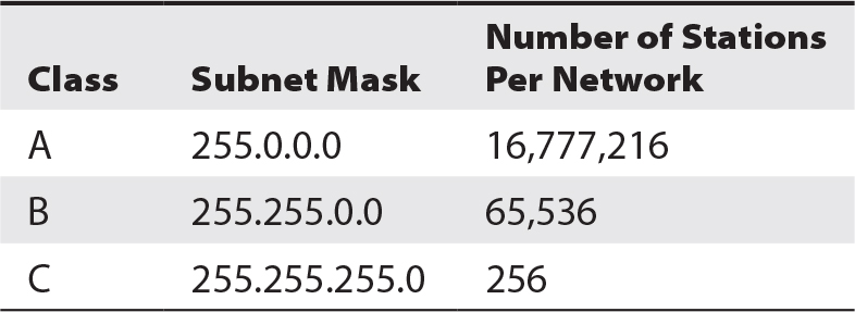
Table 5-8 Classes of Networks
The matter of the shortage of usable IP addresses in the global Internet is related to classful networks. This is discussed later in this chapter in the section “The Global Internet.”
Classless Networks It became clear that the rigidity of Class A, Class B, and Class C networks as the only ways to create subnets was wasteful. For instance, the smallest subnet available was a Class C network with its 256 available addresses. If a given subnet had only one station on it, the other 255 addresses were wasted and unused. This situation gave rise to classless networks, where subnet masks could divide networks at any arbitrary boundary.
Classless networks don’t have names like the classful networks’ Class A, Class B, and Class C. Instead, they just have subnet masks that help to serve the purpose of preserving IP addresses and allocating them more efficiently. The method, classless interdomain routing (CIDR), is used to create subnets with any arbitrary subnet mask.
Table 5-9 shows some example subnet masks that can be used to allocate IP addresses to smaller networks.
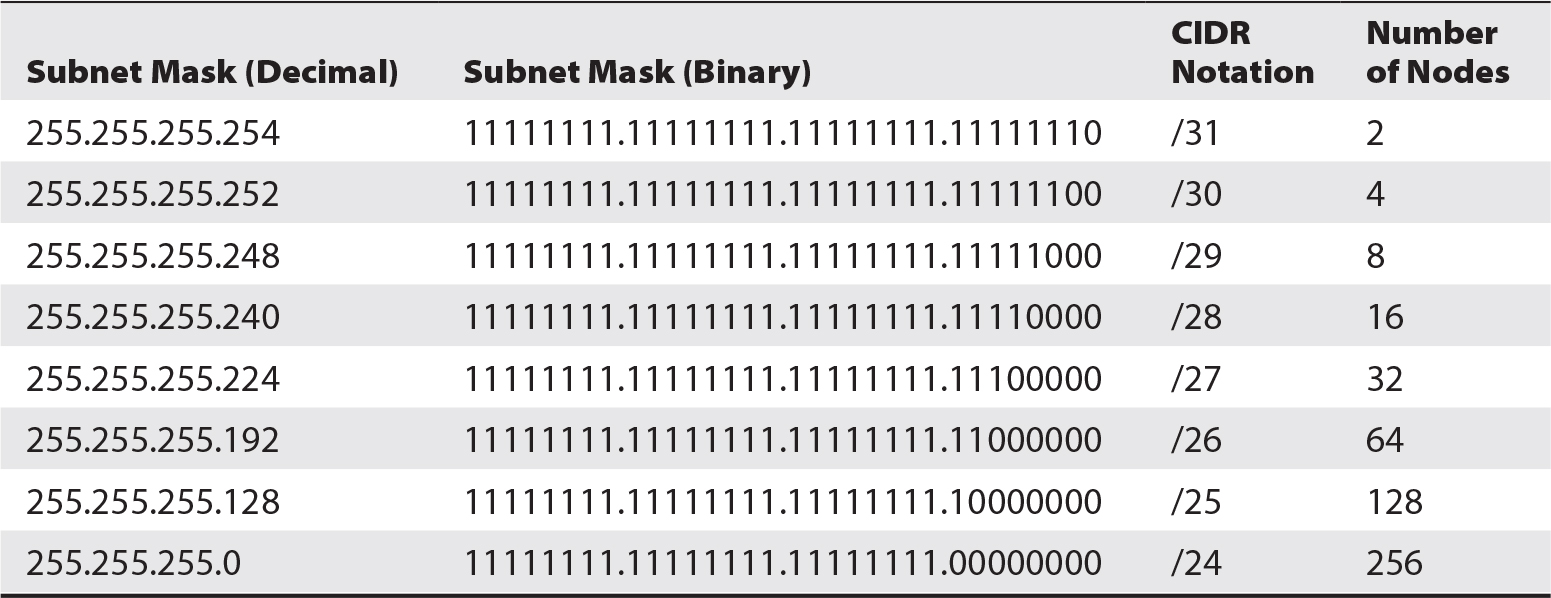
Table 5-9 Classless Network Subnet Masks
A more rapid way of expressing an IP address with its accompanying subnet mask has been developed, where the number of bits in the subnet mask follows the IP address after a slash. For example, the IP address 141.204.13.15/26 means the subnet mask is the first 26 bits (in binary) of the IP address, or 255.255.255.192. This is easier than expressing the IP address and subnet mask separately.
Virtual Networks (VLANs) In the preceding discussions of IP addresses and subnets, the classic design of TCP/IP LANs specifies that LANs are physically separate. Each LAN will have its own physical cabling and devices.
Virtual networks, known as VLANs, are logically separate networks that occupy the same physical network. VLANs are made possible through advanced configuration of network devices, including switches and routers.
The primary advantage of VLAN technology is the cost savings realized through the use of fewer network cables and devices. Another advantage of VLAN technology is the ability to divide a single network into logically separate networks, thereby creating smaller broadcast domains and reducing the potential for information leakage.
The main disadvantage is that, while they are logically separate, VLANs occupy a single physical medium: traffic on one VLAN has the potential to disrupt traffic on other VLANs, since they must share the physical network. Even with QoS capabilities, a given physical network has finite bandwidth that all VLANs must share.
Special IP Addresses Other IP addresses are used in IP that have not been discussed thus far. These other addresses and their functions are
• Loopback The IP address 127.0.0.1 (or any other address in the entire 127 address block) is a special “loopback” address that is analogous to earlier technologies, where a physical loopback plug would be connected to a network connector to confirm communications within a system or device. The 127.0.0.1 loopback address serves the same function. If a system attempts to connect to a system at IP address 127.0.0.1, it is essentially communicating with itself. A system that is able to connect to itself through its loopback address is testing its IP drivers within the operating system; during network troubleshooting, it is common to issue a “ping 127.0.0.1” or similar command to verify whether the computer’s IP software is functioning correctly.
• Broadcast The highest numeric IP address in an IP subnet is its broadcast address. When a packet is sent to a network’s broadcast address, all active stations on the network will logically receive and potentially act on the incoming message. For example, in the network 141.204.13/24, the broadcast address is 141.204.13.255. Any packet sent to that address would be sent to all stations. A ping command sent to a network’s broadcast address will cause all stations to respond with an echo reply.
Internet Layer Node Addressing: IPv6 The IP version IPv4 had a number of shortcomings, namely in the total number of available IP addresses for use in the global Internet. The new version, IPv6, takes care of the problem of available addresses, as well as other matters.
The total number of IP addresses available in IPv4 is 232, or 4,294,967,296 addresses. Because IP was originally designed prior to the proliferation of network-enabled devices, over 4 billion available IP addresses seemed more than sufficient to meet world demand. The number of IP addresses available in IPv6 is 2128, or about 3.4 × 1038 addresses.
Many new network-enabled devices support IPv6, which is enabling organizations to slowly migrate their networks. However, it is expected that IPv4 will be with us for many years. Network devices today support “dual stack” networks where IPv4 and IPv6 coexist on the same network medium.
The format of an IPv6 address is eight groups of four hexadecimal digits, separated by colons. For example,
2001:0db8:0000:0042:0000:07cc:1028:1948
Unlike IPv4 with its various schemes of subnetting, the standard size of an IPv6 subnet is 64 bits. Protocols for assigning addresses to individual nodes such as stateless address autoconfiguration generally work with /64 networks.
Transport Layer Protocols The two principal protocols in TCP/IP’s transport layer are TCP and UDP. The majority of Internet communications are based on these. This section explores TCP and UDP in detail.
TCP and UDP support the two primary types of Internet-based communication: that which requires highly reliable and ordered message delivery, and that which has a high tolerance for lost messages, respectively. TCP and UDP are uniquely designed for these two scenarios.
TCP TCP is a highly reliable messaging protocol that is used in situations where high-integrity messaging is required. The main characteristics of TCP-based network traffic are
• Unique connections TCP utilizes a connection between two stations. TCP supports several concurrent connections between any two stations, potentially numbering in the tens of thousands.
• Guaranteed message integrity TCP performs checks on the sent and received segments to ensure that the segments arrived at their destination fully intact. If the checksum indicates that the segment was altered in transit, TCP will handle retransmission.
• Guaranteed delivery TCP guarantees message delivery. This means that if an application sends a message to another application over an established TCP connection and the function sending the message receives a “success” code from the operating system, then the message was successfully delivered to the destination system. This is contrasted with the message delivery used by UDP that is discussed later in this section.
• Guaranteed delivery sequence Segments sent using TCP include sequence numbers so that the destination system can assemble arriving segments into the correct order. This guarantees that an application receiving segments from a sending application over TCP can be confident that segments are arriving in the same order in which they were sent.
UDP UDP is a lightweight messaging protocol used in situations where speed and low overhead are more important than guaranteed delivery and delivery sequence.
Unlike the connection-oriented TCP, UDP is connectionless. This means that UDP does not need to set up a connection between sending and receiving systems before datagrams can be sent; instead, the sending system just sends its datagrams to the destination system. Like TCP, datagrams can be sent to a specific port number on a destination system.
UDP does nothing to assure order of delivery. Hence, it is entirely possible that datagrams may arrive at the destination system out of order. In practice, this is a rarity, but the point is that UDP does not make any effort to reassemble datagrams into their original order upon arrival.
One might ask, why use UDP with all these shortcomings? The answer is efficiency and throughput. Without the overhead of connections and acknowledgment for every packet, UDP is simpler and requires far less bandwidth than TCP.
Protocol Data Units (PDUs)
In the telecommunications and network industry, discrete terms are used to signify the messages that are created at various layers of encapsulated protocols such as TCP/IP. These terms include

Frequently, the term packet is used to signify messages at every layer, although it is useful to know the specific terms used for each.
Furthermore, not only does UDP not guarantee the sequence of delivery, but it also does not even guarantee that the destination system will receive a datagram. In UDP, when an application sends a message to a target system, the “success” error code returned by the operating system means only that the datagram was sent. The sending system receives no confirmation that the datagram was received by the destination system.
Application Layer Protocols Scores of protocols have been developed for the TCP/IP application layer. Several are discussed in this section; they are grouped by the type of service that they provide.
File Transfer Protocols
• FTP (File Transfer Protocol) An early and still widely used protocol for batch transfer of files or entire directories from one system to another. FTP is supported by most modern operating systems, including Unix, OS X, and Windows. One drawback of FTP is that the login credentials (and all data) are transmitted unencrypted, which means that anyone eavesdropping on network communications can easily intercept them and reuse them for potentially malicious purposes.
• FTPS (File Transfer Protocol Secure, or FTP-SSL) This is an extension to the FTP protocol where authentication and file transfer are encrypted using SSL or TLS.
• SFTP (SSH File Transfer Protocol, also Secure File Transfer Protocol) This is an extension to the FTP protocol where authentication and file transfer are encrypted using SSH.
• SCP (Secure Copy) This is a file transfer protocol that is similar to rcp (remote copy) but which is protected using SSH.
• rcp (remote copy) This is an early Unix-based file transfer protocol that is used to copy files or directories from system to system. The main drawback with rcp is the lack of encryption of credentials for transferred data.
Messaging Protocols
• SMTP (Simple Mail Transfer Protocol) This is the protocol used to transport virtually all e-mail over the Internet. SMTP is used to route e-mail messages from their source over the Internet to a destination e-mail server. It is an early protocol that lacks authentication and encryption. It is partly for this reason that people should consider their e-mail to be nonprivate.
• SMTPS (Simple Mail Transfer Protocol Secure) This is a security-enhanced version of SMTP that incorporates TLS. It is sometimes known as “SMTP over TLS.”
• POP (Post Office Protocol) This is a protocol used by an end-user e-mail program to retrieve messages from an e-mail server. POP is not particularly secure because user credentials and messages are transported without encryption.
• IMAP (Internet Message Access Protocol) Like POP, this protocol is used by an end-user program to retrieve e-mail messages from an e-mail server.
• NNTP (Network News Transport Protocol) This is the protocol used to transport Usenet news throughout the Internet, and from news servers to end users using news-reading programs. Usenet news has been largely deprecated by web-based applications.
File and Directory Sharing Protocols
• NFS (Network File System) This protocol was developed to make a disk-based resource on another computer appear as a logical volume on a local computer. The NFS protocol transmits the disk requests and replies over the network.
• RPC (Remote Procedure Call) This protocol is used to permit a running process to make a procedure call to a process running on another computer. RPC supports a variety of functions that permit various types of client-server computing.
Session Protocols
• Telnet This is an early protocol that is used to establish a command-line session on a remote computer. Telnet does not encrypt user credentials as they are transmitted over the network.
• rlogin This is an early Unix-based protocol used to establish a command-line session on a remote system. Like Telnet, rlogin does not encrypt authentication or session contents.
• SSH (Secure Shell) This protocol provides a secure channel between two computers whereby all communications between them are encrypted. SSH can also be used as a tunnel to encapsulate and thereby protect other protocols.
• HTTP (Hypertext Transfer Protocol) This protocol is used to transmit web page contents from web servers to users who are using web browsers.
• HTTPS (Hypertext Transfer Protocol Secure) This is similar to HTTP in its use for transporting data between web servers and browsers. HTTPS is not a separate protocol, but instead is the instance where HTTP is encrypted with SSL or TLS.
• RDP (Remote Desktop Protocol) This proprietary protocol from Microsoft is used to establish a graphical console interface to another computer.
Management Protocols
• SNMP (Simple Network Management Protocol) This protocol is used by network devices and systems to transmit management messages indicating a need for administrative attention. SNMP is used to monitor networks and their components; SNMP messages are generated when events warrant attention by network engineers or system engineers. In larger organizations, SNMP messages are collected by a network management system that displays the network topology and devices that require attention.
• NTP (Network Time Protocol) This protocol is used to synchronize the time-of-day clocks on systems, using time-reference standards. The use of NTP is vital because the time clocks in computers often drift (run too fast or too slow), and it is important for all computers’ time clocks in an organization to be precisely the same so that complex events can be more easily managed and correlated.
Directory Services Protocols
• DNS (Domain Name System) This is a vital Internet-based service that is used to translate domain names (such as www.isecbooks.com) into IP addresses. A call to a DNS server is a prerequisite for system-to-system communications where one system wants to establish a communications session with another system and where it knows only the domain name for the target system.
• LDAP (Lightweight Directory Access Protocol) This protocol is used as a directory service for people and computing resources. LDAP is frequently used as an enterprise authentication and computing resource service. Microsoft Active Directory is an adaptation of LDAP.
• X.500 This protocol is a functional predecessor to LDAP that provides directory services.
TCP/IP Network Devices Network devices are required to facilitate the transmission of packets among TCP/IP networks. These devices include
• Router This device is used to connect two or more separate TCP/IP networks to each other. A router typically has two or more network interface connectors, each of which is connected to a separate network. A router that is used to connect LANs is typically equipped with Ethernet interfaces, while a router used to connect LANs with WANs will have one or more Ethernet connectors and one or more connectors for WAN protocols such as SONET or MPLS. A router may also have an access control list (ACL, which is functionally similar to a firewall) that the router uses to determine whether packets passing through it should be permitted to proceed to their destination.
• Firewall This device is used to control which network packets are permitted to cross network boundaries. Typically, a firewall will block or permit packets to pass based on their source IP address, destination IP address, and protocol. Firewalls are typically used at an organization’s network boundary to protect it from unwanted network traffic from the Internet but still permit traffic to the organization’s e-mail and web servers, for instance.
• Application firewall This device is used to control packets being sent to an application server, blocking those that contain unwanted or malicious content. An application firewall can help to protect a web server from attacks such as SQL injection or buffer overflow.
• Intrusion prevention system (IPS) This device is used to detect and potentially block network packets that may be malicious.
• Proxy server This device is typically used to control end-user access to web sites on the Internet. A proxy server typically controls access according to policy.
• Layer 3 switch This device routes packets between different VLANs. Functionally, this is the same as a router; a router performs network routing using software running on a microprocessor, while a layer 3 switch performs this routing using a dedicated application-specific integrated circuit (ASIC), giving it much better performance than a router.
• Layer 4 switch This device is used to route packets to destinations based on TCP and UDP port numbers.
• Layer 4-7 switch Also known as a content switch, web switch, or application switch, this device is used to route packets to destinations based on their internal content. Layer 4-7 switches can be used to route incoming network traffic intelligently to various servers based on policy, performance, or availability.
Interestingly, the names of layer 3, layer 4, and layer 4-7 switches are based on their OSI network model layers even though these are TCP network devices.
Other network devices such as hubs, switches, and gateways are discussed in the section “Ethernet,” earlier in this chapter.
Software-Defined Networking Software-defined networking (SDN) is a new class of capabilities where network infrastructure is created, configured, and managed in the context of virtualization. In SDN, routers, firewalls, switches, IPSs, and other network devices are no longer physical devices but software programs that run in virtualized environments.
SDN gives organizations greater agility with regard to their network infrastructure: instead of procuring additional network devices as network infrastructure needs grow and change, virtual network devices are instantiated and deployed immediately.
Organizations and groups of organizations are developing SDN standards, such as OpenFlow, to build consistent practices to SDN.
The Global Internet
The TCP/IP networks owned by businesses, government, military, and educational institutions are interconnected; collectively this is known as the global Internet—or just the Internet. It is in the context of the global Internet that TCP/IP topics such as node addressing, routing, domain naming, and other matters are most relevant.
IP Addressing The allocation of routable IP addresses is coordinated through a central governing body known as the Internet Assigned Numbers Authority (IANA). This coordination is necessary so that duplicate addresses are not allocated, which would cause confusion and unreachable systems.
The original IP address allocation scheme appears in Table 5-10.
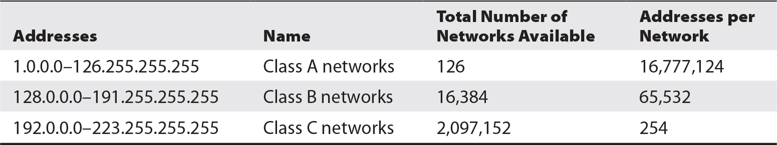
Table 5-10 Internet IP Address Allocation
When TCP/IP was established, the entire IP address space (that is, the entire range of possible addresses from 1.1.1.1 through 255.255.255.255) appeared to be far more than would ever be needed. However, it soon became apparent that the original IP address allocation scheme was woefully inadequate. This led to the establishment of ranges for private networks and rules for their use. Private address ranges are listed in Table 5-11.
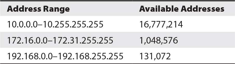
Table 5-11 Private Address Ranges
Availability of a sufficient number of publicly routable IP addresses has been addressed with IPv6. See the sidebar on IPv6 earlier in this chapter.
NOTE The number of available addresses does not take network IDs and broadcast addresses into account, which will make the number of actual addresses lower. This will vary, based upon how networks are subnetted.
The private addresses listed in Table 5-11 are not “routable.” This means that no router on the Internet is permitted to forward a packet with any IP address within any of the private address ranges. These IP addresses are intended for use wholly within organizations to facilitate communication among internal systems. When any system with a private address needs to communicate with a system on the Internet, its communication is required to pass through a gateway that will translate the internal IP address to a public routable IP address. The NAT (Network Address Translation) method is often used for this purpose.
Domain Name System The Internet utilizes the Domain Name System (DNS), a centrally coordinated domain name registration system. Several independent domain registrars are licensed to issue new domain names to individuals and corporations in exchange for modest fees. These domain registrars often also provide DNS services on behalf of each domain name’s owner.
New and changed domain names are periodically uploaded to the Internet’s “root” DNS servers, enabling users to access services by referring to domain names such as www.myblogsite.com.
Network Routing Routers used by Internet service providers (ISPs) receive and forward IP traffic to and from any of the millions of systems that are connected to the Internet. These big routers exchange information on the whereabouts of all publicly reachable networks in large “routing tables” that contain rules about the topology of the Internet and the addresses and locations of networks. Internet routers exchange this information through the use of routing protocols, which are “out-of-band” messages that contain updates to the topology and IP addressing of the Internet. Some of these protocols are
• BGP (Border Gateway Protocol)
• OSPF (Open Shortest Path First)
• IGRP (Interior Gateway Routing Protocol)
• EIGRP (Enhanced Interior Gateway Routing Protocol)
• EGP (Exterior Gateway Protocol, now obsolete)
• IS-IS (Intermediate System to Intermediate System)
• RIP (Routing Information Protocol; this is one of the earliest protocols and no longer used for Internet routing)
Organizations with several internal networks also use one or more of these routing protocols so that their routers can keep track of the changing topology and addressing of its network.
Global Internet Applications Applications are what make the Internet popular. From electronic banking to e-commerce, entertainment, news, television, and movies, applications on the Internet have made it possible for people anywhere to view or receive virtually any kind of information and content.
The World Wide Web The World Wide Web encompasses all of the world’s web servers, which are accessible from workstations of many types that use web browser programs. Requests to web servers, and content returned to browsers, are issued using HTTP and HTTPS. Content sent to browsers consists primarily of text written in HTML, as well as rich text, including images and dynamic content such as audio and video.
The World Wide Web rapidly gained in popularity because information and applications could be accessed from anywhere without any special software. Readily available tools simplified the publication of many types of data to the Web.
The most critical service that supports the World Wide Web is DNS. This service translates server domain names into IP addresses. For example, if a user wants to visit www.mheducation.com, the operating system running the user’s browser will make a request to a local DNS server for the IP address corresponding to www.mheducation.com. After the DNS server responds with the server’s IP address, the user’s browser can issue a request to the server (at 52.4.128.203) and then receive content from the server.
Web servers can act as application servers. Authenticated users can receive menus, data entry screens and forms, query results, and reports, all written in HTML, all with only web browser software. Web servers that function as application servers have built-in protocols to communicate to back-end application servers and database management systems.
E-mail Electronic mail was one of the Internet’s first applications. E-mail existed before the Internet, but it was implemented on the Internet as a way to send messages not only within organizations but also between them. The SMTP, POP, and IMAP protocols were developed and adopted early on, and are still widely used today. SMTP remains the backbone of Internet e-mail transport. Organizations increasingly are using SMTPS to protect the contents of e-mail messages.
Instant Messaging E-mail, while far more rapid than postal-delivered letters, can still be slow at times. Instant messaging (IM), originally developed on DEC PDP-11 computers in the 1970s and on Unix in the early 1980s, was adapted to the Internet in the early 1990s. Like all other Internet applications, IM is based on the TCP/IP protocol suite and enables people all over the world to communicate in real time via text, voice, and video.
Network Tunneling Tunneling refers to a number of protocols that permit communications between two endpoints to be encapsulated in a logical “tunnel.” Often, a tunnel is used to protect communications containing sensitive data that is transported over public networks such as the Internet. Packets in a tunnel can be encrypted, which hides the true endpoint IP addresses as well as the message contents, to prevent any intermediate system from eavesdropping on those communications. Tunnels are frequently called virtual private networks (VPNs), because they provide both security (through encryption and authentication) and abstraction (by hiding the details of the path between systems).
VPNs are frequently used for end-user remote access into an organization’s network. When an end user wants to connect to an organization’s internal network, the network will establish a session with a VPN server and provide authentication credentials. An encrypted tunnel will then be established that gives the end user the appearance of being connected to the internal network.
Network Management
Network management is the function of ensuring that a data network continues to support business objectives. The activities that take place include monitoring network devices, identifying problems, and applying remedies as needed to restore network operations.
The purpose of network management is the continued reliable operation of an organization’s data network. A properly functioning data network, in turn, supports business applications that support critical business processes.
Network Management Tools Network management requires tools that are used to monitor, troubleshoot, and maintain data networks. This permits an IT organization to ensure the continuous operation of its data network so that it has sufficient capacity and capability to support applications and services vital to the organization’s ongoing business operations.
The tools that are used to fulfill this mission include
• Network management system This software application collects network management messages that are sent from network devices and systems. These messages alert the management system that certain conditions exist on the device, some of which may require intervention. Some network management systems also contain the means for network administrators and engineers to diagnose and correct conditions that require attention.
• Network management report Network management systems generally have the ability to generate reports showing key metrics such as network availability, utilization, response time, and downtime. Reports from helpdesk systems or incident management systems also help in communicating the health of an organization’s networks.
• Network management agent An agent is a small software module that resides on managed network devices and other systems. Agents monitor operations on the device or system and transmit messages to a centralized network management system when needed.
• Incident management system This is a general-purpose ticketing engine that captures and tracks individual incidents and report on an organization’s timely response to them. Often, network management systems and incident management systems can be integrated together so that conditions requiring attention in the network can automatically create a ticket that will be used to track the course of the incident until it is closed.
• Sniffer This software program can be installed on a network-attached system or a separate hard device to capture and analyze network traffic.
• Security incident and event management (SIEM) system A SIEM (pronounced “sim”) system collects, correlates, analyzes, reports on, and creates actionable alerts based on the individual error and event messages generated by the systems and devices in an environment.
Organizations employing network management tools often implement a NOC staffed with personnel who monitor and manage network devices and services. Often this function is outsourced to a managed security service provider (MSSP).