Chapter 4
Radio Frequency Signal and Antenna Concepts
In this chapter, you will learn about the following:
 Azimuth and elevation charts (antenna radiation envelopes)
- Interpreting polar charts
- Beamwidth
- Antenna types
- Omnidirectional antennas
- Semidirectional antennas
- Highly directional antennas
- Sector antennas
- Antenna arrays
- Static beamforming
- Dynamic beamforming
- Transmit beamforming
- Visual line of sight
- RF line of sight
- Fresnel zone
- Earth bulge
- Antenna polarization
- Antenna diversity
- Multiple-input multiple-output (MIMO)
- MIMO antennas
- Indoor MIMO antennas
- Outdoor MIMO antennas
- Antenna connection and installation
- Voltage standing wave ratio (VSWR)
- Signal loss
- Antenna mounting
- Placement
- Outdoor mounting considerations
- Indoor mounting considerations
- Appropriate use and environment
- Ingress Protection Rating
- NEMA Enclosure Rating
- ATEX directives
- National Electrical Code (NEC)
- Orientation and alignment
- Safety
- Maintenance
- Antenna accessories
- Cables
- Connectors
- Splitters
- Amplifiers
- Attenuators
- Lightning arrestors
- Grounding rods and wires
- Regulatory Compliance
To be able to communicate between two or more transceivers, the radio frequency (RF) signal must be radiated from the antenna of the transmitter with enough power so that it is received and understood by the receiver. The installation of antennas has the greatest ability to affect whether or not the communication is successful. Antenna installation can be as simple as placing an access point in the middle of a small office to provide full coverage for your company, or it can be as complex as installing an assortment of directional antennas, kind of like piecing together a jigsaw puzzle. Do not fear this process; with proper understanding of antennas and how they function, you may find successfully planning for and installing antennas in a wireless network to be a skillful and rewarding task.
This chapter focuses on the categories and types of antennas and the different ways that they can direct an RF signal. Choosing and installing antennas is like choosing and installing lighting in a home. When installing home lighting, you have many choices: table lamps, ceiling lighting, narrow- or wide-beam directional spotlights. In Chapter 3, “Radio Frequency Components, Measurements, and Mathematics,” you were introduced to the concept of antennas focusing RF signal. In this chapter, you will learn about the various types of antennas, their radiation patterns, and how to use the different antennas in different environments. You will also learn that the installation and alignment of omnidirectional antennas should vary depending on whether the access point supports 802.11n, 802.11ac, or legacy physical layer technologies.
You will also learn that even though we often use light to explain RF radiation, differences exist between the way the two behave. You will learn about aiming and aligning antennas, and you will learn that what you see is not necessarily what you will get.
In addition to learning about antennas, you will learn about the accessories that may be needed for proper antenna installation. In office environments, you may simply need to connect the antenna to the access point. In outdoor installations, you will need special cable and connectors, lightning arrestors, and special mounting brackets. In this chapter, we will introduce you to the components necessary for successfully installing an antenna.
To summarize, in this chapter you will gain the knowledge that will enable you to properly select, install, and align antennas. These skills will help you successfully implement a wireless network, whether it is a point-to-point network between two buildings or a network providing wireless coverage throughout an office building.
Azimuth and Elevation Charts (Antenna Radiation Envelopes)
There are many types of antennas designed for many different purposes, just as there are many types of lights designed for many different purposes. When purchasing lighting for your home, it is easy to compare two lamps by turning them on and looking at the way each disperses the light. Unfortunately, it is not possible to compare antennas in the same way.
Actual side-by-side comparison of antennas requires you to walk around the antenna with an RF meter, take numerous signal measurements, and then plot the measurements either on the ground or on a piece of paper that represents the environment. Besides the fact that this is a time-consuming task, the results could be skewed by outside influences on the RF signal, such as furniture or other RF signals in the area. To assist potential buyers with their purchasing decision, antenna manufacturers create azimuth charts and elevation charts, commonly known as radiation patterns, for their antennas. These radiation patterns are created in controlled environments where the results cannot be skewed by outside influences and represent the signal pattern that is radiated by a particular model of antenna. These charts are commonly known as polar charts or antenna radiation envelopes.
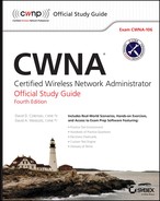
Figure 4.1 shows the azimuth and elevation charts of an omnidirectional antenna. The azimuth chart, labeled H-plane, shows the top-down view of the radiation pattern of the antenna. Since this is an omnidirectional antenna, as you can see from the azimuth chart, its radiation pattern is almost perfectly circular. The elevation chart, labeled E-plane, shows the side view of the radiation pattern of the antenna. There is no standard that requires the antenna manufacturers to align the degree marks of the chart with the direction that the antenna is facing, so unfortunately it is up to the reader of the chart to understand and interpret it.
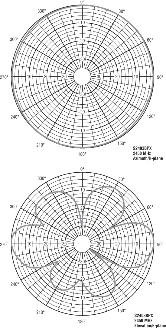
Figure 4.1 Azimuth and elevation charts
Here are a few statements that will help you interpret the radiation charts:
- In either chart, the antenna is placed at the center of the chart.
- Azimuth chart = H-plane = top-down view
- Elevation chart = E-plane = side view
The outer ring of the chart usually represents the strongest signal of the antenna. The chart does not represent distance or any level of power or strength. It represents only the relationship of power between different points on the chart.
One way to think of the chart is to consider the way a shadow behaves. If you were to move a flashlight closer or farther from your hand, the shadow of your hand would grow larger or smaller. The shadow does not represent the size of the hand. The shadow represents the relative shape of the hand. Whether the shadow is large or small, the shape and pattern of the shadow of the hand is identical. With an antenna, the radiation pattern will grow larger or smaller depending on how much power the antenna receives, but the shape and the relationships represented by the patterns will always stay the same.
Interpreting Polar Charts
As we stated, the antenna azimuth (H-plane) and elevation (E-plane) charts are commonly referred to as polar charts. These charts are often misinterpreted and misread. One of the biggest reasons these charts are misinterpreted is that they represent the decibel (dB) mapping of the antenna coverage. This dB mapping represents the radiation pattern of the antenna; however, it does this using a logarithmic scale instead of a linear scale. Remember that the logarithmic scale is a variable scale, based on exponential values, so the polar chart is actually a visual representation using a variable scale.
Take a look at Figure 4.2. The numbers inside the four boxes in the upper-left corner tell you how long and wide each box is. So, even though visually in our drawing we represented the boxes as the same size, in reality each one is twice as long and wide as the previous one. It is easier to draw the four boxes as the same physical size and just put the number in the box to represent the actual size of the box. In the middle drawing, we drew the boxes showing the relative size of the four boxes.
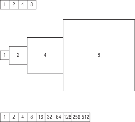
Figure 4.2 Logarithmic/linear comparison
What if we had more boxes, say 10? By representing each box using the same-sized drawing, it is easier to illustrate the boxes, as shown with the boxes in the lower-left corner. In this example, if we tried to show the actual differences in size, as we did in the middle of the drawing, we could not fit this drawing on the page in the book. In fact, the room that you are in may not have enough space for you to even draw this. Because the scale changes so drastically, it is necessary to not draw the boxes to scale so that we can still represent the information.
In Chapter 3, you learned about RF math. In that chapter, one of the rules that you learned was the rule of 6 dB, which indicates that a 6 dB decrease of power decreases the distance the signal travels by half. A 10 dB decrease of power decreases the distance the signal travels by approximately 70 percent. In Figure 4.3, the left polar chart displays the logarithmic representation of the elevation chart of an omnidirectional antenna. This is what you are typically looking at on an antenna brochure or specification sheet. Someone who is untrained in reading these charts would look at the chart and be impressed with how much vertical coverage the antenna provides but would likely be disappointed with the actual coverage. When reading the logarithmic chart, you must remember that for every 10 dB decrease from the peak signal, the actual distance decreases by 70 percent. Each concentric circle on this logarithmic chart represents a change of 5 dB. Figure 4.3 shows the logarithmic pattern of an elevation chart of an omnidirectional antenna along with a linear representation of it's coverage. Notice that the first side lobe is about 10 dB weaker than the main lobe. Remember to compare where the lobes are relative to the concentric circles. This 10 dB decrease on the logarithmic chart is equal to a 70 percent decrease in range on the linear chart. Comparing both charts, you see that the side lobes on the logarithmic chart are essentially insignificant when adjusted to the linear chart. As you can see, this omnidirectional antenna has very little vertical coverage.
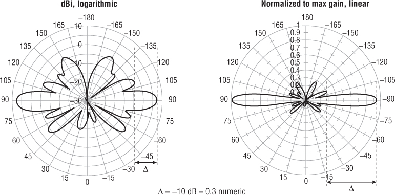
Figure 4.3 Omnidirectional polar chart (E-plane)
Image © Aruba Networks, Inc. All rights reserved. Used with permission.
To give you another comparison, Figure 4.4 shows the logarithmic pattern of the elevation chart of a directional antenna along with a linear representation of the vertical coverage area of this antenna. We rotated the polar chart on its side so that you can better visualize the antenna mounted on the side of a building and aiming at another building.
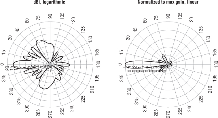
Figure 4.4 Directional polar chart (E-plane)
Image © Aruba Networks, Inc. All rights reserved. Used with permission.
Beamwidth
Many flashlights have adjustable lenses, enabling the user to widen or tighten the concentration of light. RF antennas are capable of focusing the power that is radiating from them, but unlike flashlights, antennas are not adjustable. The user must decide how much focus is desired prior to the purchase of the antenna.
Beamwidth is the measurement of how broad or narrow the focus of an antenna is—and is measured both horizontally and vertically. It is the measurement from the center, or strongest point, of the antenna signal to each of the points along the horizontal and vertical axes where the signal decreases by half power (–3 dB), as seen in Figure 4.5. These –3 dB points are often referred to as half-power points. The distance between the two half-power points on the horizontal axis is measured in degrees, giving the horizontal beamwidth measurement. The distance between the two half-power points on the vertical axis is also measured in degrees, giving the vertical beamwidth measurement.
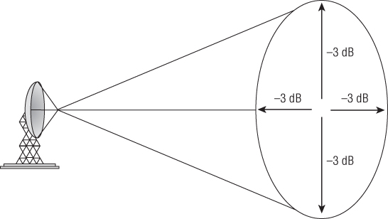
Figure 4.5 Antenna beamwidth
Most of the time when you are deciding which antenna will address your communications needs, you will look at the manufacturer's spec sheets to determine the technical specifications of the antenna. In these brochures, the manufacturer typically includes the numerical values for the horizontal and vertical beamwidths of the antenna. It is important for you to understand how these numbers are calculated. Figure 4.6 illustrates the process.
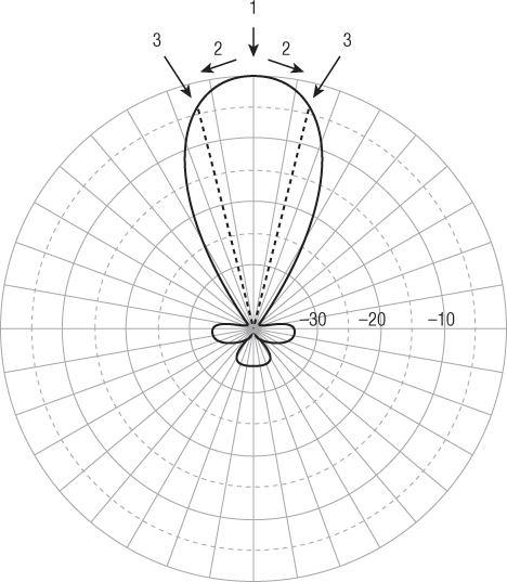
Figure 4.6 Beamwidth calculation
- First determine the scale of the polar chart.
On this chart, you can see that the solid circles represent the –10 dB, –20 dB, and –30 dB lines and the dotted circles therefore represent the –5 dB, –15 dB, and –25 dB lines. These represent the dB decrease from the peak signal.
- To determine the beamwidth of this antenna, first locate the point on the chart where the antenna signal is the strongest.
In this example, the signal is strongest where the number 1 arrow is pointing.
- Move along the antenna pattern away from the peak signal (as shown by the two number 2 arrows) until you reach the point where the antenna pattern is 3 dB closer to the center of the diagram (as shown by the two number 3 arrows).
This is why you needed to know the scale of the chart first.
- Draw a line from each of these points to the middle of the polar chart (as shown by the dark dotted lines).
- Measure the distance in degrees between these lines to calculate the beamwidth of the antenna.
In this example, the beamwidth of this antenna is about 28 degrees.
It is important to realize that even though the majority of the RF signal that is generated is focused within the beamwidth of the antenna, a significant amount of signal can still radiate from outside the beamwidth, from what is known as the antenna's side or rear lobes. As you look at the azimuth charts of different antennas, you will notice that some of these side and rear lobes are fairly significant. Although the signal of these lobes is drastically less than the signal of the main beamwidth, they are dependable, and in certain implementations very functional. It is important when aligning point-to-point antennas that you make sure they are actually aligned to the main lobe and not a side lobe.
Table 4.1 shows the types of antennas that are used in 802.11 communications.
Table 4.1 Antenna beamwidth
| Antenna types | Horizontal beamwidth (in degrees) | Vertical beamwidth (in degrees) |
| Omnidirectional | 360 | 7 to 80 |
| Patch/panel | 30 to 180 | 6 to 90 |
| Yagi | 30 to 78 | 14 to 64 |
| Sector | 60 to 180 | 7 to 17 |
| Parabolic dish | 4 to 25 | 4 to 21 |
Antenna Types
There are three main categories of antennas:
- Omnidirectional: Omnidirectional antennas radiate RF in a fashion similar to the way a table or floor lamp radiates light. They are designed to provide general coverage in all directions.
- Semidirectional: Semidirectional antennas radiate RF in a fashion similar to the way a wall sconce radiates light away from the wall or the way a street lamp shines light down on a street or a parking lot, providing a directional light across a large area.
- Highly directional: Highly directional antennas radiate RF in a fashion similar to the way a spotlight focuses light on a flag or a sign.
In addition to antennas acting as radiators and focusing signals that are being transmitted, they focus signals that are received. If you were to walk outside and look up at a star, it would appear fairly dim. If you were to look at that same star through binoculars, it would appear brighter. If you were to use a telescope, it would appear even brighter. Antennas function in a similar way. Not only do they amplify signal that is being transmitted, they also amplify signal that is being received. High-gain microphones operate in the same way, enabling you to not only watch the action of your favorite sport on television but to also hear the action.
Omnidirectional Antennas
Omnidirectional antennas radiate RF signal in all directions. The small, rubber-coated dipole antenna, often referred to as a rubber duck antenna, is the classic example of an omnidirectional antenna and is the default antenna of many access points, although most of the antennas nowadays are encased in plastic instead of rubber. A perfect omnidirectional antenna would radiate RF signal like the theoretical isotropic radiator from Chapter 3, “Radio Frequency Components, Measurements, and Mathematics.” The closest thing to an isotropic radiator is the omnidirectional dipole antenna.
An easy way to explain the radiation pattern of a typical omnidirectional antenna is to hold your index finger straight up (this represents the antenna) and place a bagel on it as if it were a ring (this represents the RF signal). If you were to slice the bagel in half horizontally, as if you were planning to spread butter on it, the cut surface of the bagel would represent the azimuth chart, or H-plane, of the omnidirectional antenna. If you took another bagel and sliced it vertically instead, essentially cutting the hole that you are looking through in half, the cut surface of the bagel would now represent the elevation, or E-plane, of the omnidirectional antenna.
In Chapter 3, you learned that antennas can focus or direct the signal that they are transmitting. It is important to know that the higher the dBi or dBd value of an antenna, the more focused the signal. When discussing omnidirectional antennas, it is not uncommon to initially question how it is possible to focus a signal that is radiated in all directions. With higher-gain omnidirectional antennas, the vertical signal is decreased and the horizontal power is increased.
Figure 4.7 shows the elevation view of three theoretical antennas. Notice that the signal of the higher-gain antennas is elongated, or more focused horizontally. The horizontal beamwidth of omnidirectional antennas is always 360 degrees, and the vertical beamwidth ranges from 7 to 80 degrees, depending on the particular antenna.
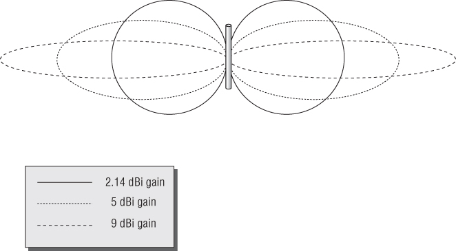
Figure 4.7 Vertical radiation patterns of omnidirectional antennas
Because of the narrower vertical coverage of the higher-gain omnidirectional antennas, it is important to carefully plan how they are used. Placing one of these higher-gain antennas on the first floor of a building may provide good coverage to the first floor, but because of the narrow vertical coverage, the second and third floors may receive minimal signal. In some installations, you may want this; in others, you may not. Indoor installations typically use low-gain omnidirectional antennas with gain of about 2.14 dBi.
Antennas are most effective when the length of the element is an even fraction (such as 1/4 or 1/2) or a multiple of the wavelength (λ). A 2.4 GHz half-wave dipole antenna (see Figure 4.8) consists of two elements, each 1/4 wave in length (about 1 inch), running in the opposite direction from each other. Higher-gain omnidirectional antennas are typically constructed by stacking multiple dipole antennas on top of each other and are known as collinear antennas.
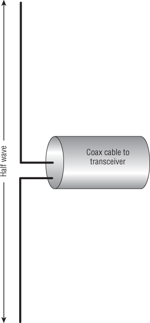
Figure 4.8 Half-wave dipole antenna
Omnidirectional antennas are typically used in point-to-multipoint environments. The omnidirectional antenna is connected to a device (such as an access point) that is placed at the center of a group of client devices, providing central communications capabilities to the surrounding clients. High-gain omnidirectional antennas can also be used outdoors to connect multiple buildings together in a point-to-multipoint configuration. A central building would have an omnidirectional antenna on its roof, and the surrounding buildings would have directional antennas aimed at the central building. In this configuration, it is important to make sure that the gain of the omnidirectional antenna is high enough to provide the coverage necessary but not so high that the vertical beamwidth is too narrow to provide an adequate signal to the surrounding buildings.
Figure 4.9 shows an installation where the gain is too high. The building to the left will be able to communicate, but the building on the right is likely to have problems. To solve the problem that is pictured in Figure 4.9, sector arrays using a down-tilt configuration are used instead of high-gain omnidirectional antennas. Sector antennas are discussed later in this chapter.
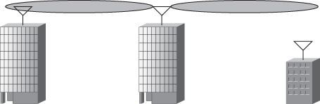
Figure 4.9 Improperly installed omnidirectional antenna
Semidirectional Antennas
Unlike omnidirectional antennas that radiate RF signals in all directions, semidirectional antennas are designed to direct a signal in a specific direction. Semidirectional antennas are used for short- to medium-distance communications, with long-distance communications being served by highly directional antennas.
It is common to use semidirectional antennas to provide a network bridge between two buildings in a campus environment or down the street from each other. Longer distances would be served by highly directional antennas.
Three types of antennas fit into the semidirectional category:
- Patch
- Panel
- Yagi (pronounced YAH-gee)
Patch and panel antennas, as shown in Figure 4.10, are more accurately classified or referred to as planar antennas. Patch refers to a particular way of designing the radiating elements inside the antenna. Unfortunately, it has become common practice to use the terms patch antenna and panel antenna interchangeably. If you are unsure of the antenna's specific design, it is better to refer to it as a planar antenna.
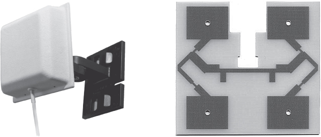
Figure 4.10 The exterior of a patch antenna and the internal antenna element
These antennas can be used for outdoor point-to-point communications up to about a mile but are more commonly used as a central device to provide unidirectional coverage from the access point to the clients in an indoor environment. It is common for patch or panel antennas to be connected to access points to provide directional coverage within a building. Planar antennas can be used effectively in libraries, warehouses, and retail stores with long aisles of shelves. Because of the tall, long shelves, omnidirectional antennas often have difficulty providing RF coverage effectively.
In contrast, planar antennas can be placed high on the side walls of the building, aiming through the rows of shelves. The antennas can be alternated between rows, with every other antenna being placed on the opposite wall. Since planar antennas have a horizontal beamwidth of 180 degrees or less, a minimal amount of signal will radiate outside of the building. With the antenna placement alternated and aimed from opposite sides of the building, the RF signal is more likely to radiate down the rows, providing the necessary coverage.
Planar antennas are also often used to provide coverage for long hallways with offices on each side or hospital corridors with patient rooms on each side. A planar antenna can be placed at the end of the hall and aimed down the corridor. A single planar antenna can provide RF signal to some or all of the corridor and the rooms on each side and some coverage to the floors above and below. How much coverage will depend on the power of the transmitter, the gain and beamwidth (both horizontal and vertical) of the antenna, and the attenuation properties of the building.
Before the advent of 802.11 MIMO radios, patch and panel antennas were used indoors with legacy 802.11a/b/g radios to help reduce reflections and hopefully reduce the negative effects of multipath. Semidirectional indoor antennas were often deployed in high multipath environments, such as warehouses or retail stores with a lot of metal racks or shelving. Now that MIMO technology is prevalent, patch and panel antennas are no longer needed to reduce multipath because multipath is constructive with MIMO technology.
802.11n and 802.11ac MIMO patch antennas are still used indoors but for a much different reason. The most common use case for deploying a MIMO patch antenna indoors is a high-density environment. A high-density environment can be described as a small area where numerous Wi-Fi client devices exist. An example might be a gymnasium at a school or a meeting hall packed with people using multiple Wi-Fi radios. In a high-density scenario, an omnidirectional antenna might not be the best solution for coverage. MIMO patch and panel antennas are often mounted from the ceiling downward to provide tight “sectors” of coverage. The most common use of indoor MIMO patch antennas is for high-density environments.
Yagi-Uda antennas, shown in Figure 4.11, are more commonly known as just Yagi antennas. They are typically used for short- to medium-distance point-to-point communications of up to about 2 miles, although high-gain Yagi antennas can be used for longer distances.
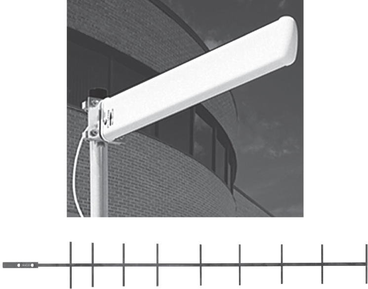
Figure 4.11 The exterior of a Yagi antenna and the internal antenna element
Another benefit of semidirectional antennas is that they can be installed high on a wall and tilted downward toward the area to be covered. This cannot be done with an omnidirectional antenna without causing the signal on the other side of the antenna to be tilted upward. Since the only RF signal that radiates from the back of a semidirectional antenna is incidental, the ability to aim it vertically is an additional benefit.
Figure 4.12 shows the radiation patterns of a typical semidirectional panel antenna. Remember that these are actual azimuth and elevation charts from a specific antenna and that every manufacturer and model of antenna will have a slightly different radiation pattern.
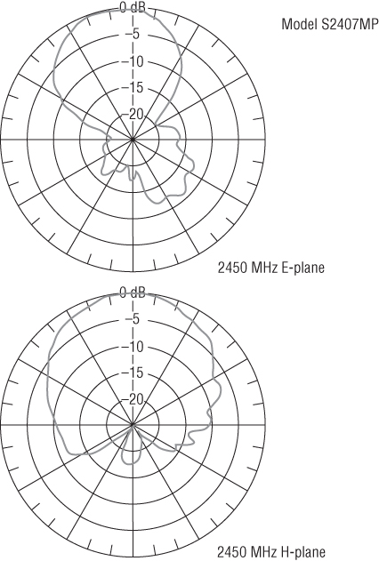
Figure 4.12 Radiation pattern of a typical semidirectional panel antenna
Highly Directional Antennas
Highly directional antennas are strictly used for point-to-point communications, typically to provide network bridging between two buildings. They provide the most focused, narrow beamwidth of any of the antenna types.
There are two types of highly directional antennas: parabolic dish antennas and grid antennas:
- Parabolic Dish Antenna The parabolic dish antenna is similar in appearance to the small digital satellite TV antennas that can be seen on the roofs of many houses.
- Grid Antenna As pictured in Figure 4.13, the grid antenna resembles the grill of a barbecue, with the edges slightly curved inward. The spacing of the wires on a grid antenna is determined by the wavelength of the frequencies that the antenna is designed for.
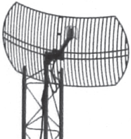
Figure 4.13 Grid antenna
Because of the high gain of highly directional antennas, they are ideal for long-distance point-to-point communications.
Because of the long distances and narrow beamwidth, highly directional antennas are affected more by antenna wind loading, which is antenna movement or shifting caused by wind. Even slight movement of a highly directional antenna can cause the RF beam to be aimed away from the receiving antenna, interrupting RF communications. In high-wind environments, grid antennas, because of the spacing between the wires, are less susceptible to wind load and may be a better choice.
Another option in high-wind environments is to choose an antenna with a wider beamwidth. In this situation, if the antenna were to shift slightly, the signal would still be received because of its wider coverage area. Keep in mind that a wider beam means less gain. If a solid dish is used, it is highly recommended that a protective cover known as a radome be used to help offset some of the effects of the wind. No matter which type of antenna is installed, the quality of the mount and antenna will have a huge effect in reducing wind load.
Sector Antennas
Sector antennas are a special type of high-gain, semidirectional antenna that provides a pie-shaped coverage pattern. These antennas are typically installed in the middle of the area where RF coverage is desired and placed back to back with other sector antennas. Individually, each antenna services its own piece of the pie, but as a group, all of the pie pieces fit together and provide omnidirectional coverage for the entire area. Combining multiple sector antennas to provide 360 degrees of horizontal coverage, as shown in Figure 4.14, is known as a sectorized array.
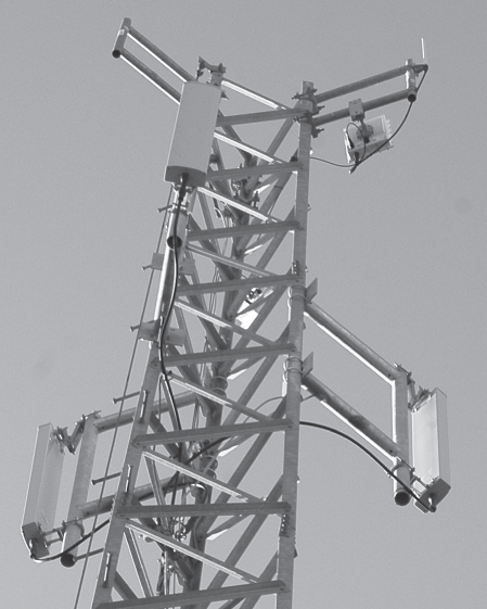
Figure 4.14 Sectorized array
Unlike other semidirectional antennas, a sector antenna generates very little RF signal behind the antenna (back lobe) and therefore does not interfere with the other sector antennas that it is working with. The horizontal beamwidth of a sector antenna is from 60 to 180 degrees, with a narrow vertical beamwidth of 7 to 17 degrees. Sector antennas typically have a gain of at least 10 dBi.
Installing a group of sector antennas to provide omnidirectional coverage for an area provides many benefits over installing a single omnidirectional antenna:
- To begin with, sector antennas can be mounted high over the terrain and tilted slightly downward, with the tilt of each antenna at an angle appropriate for the terrain it is covering. Omnidirectional antennas can also be mounted high over the terrain; however, if an omnidirectional antenna is tilted downward on one side, the other side will be tilted upward.
-
Since each antenna covers a separate area, each antenna can be connected to a separate transceiver and can transmit and receive independently of the other antennas.
This provides the capability for all the antennas to be transmitting at the same time, providing much greater throughput. A single omnidirectional antenna is capable of transmitting to only one device at a time.
- The last benefit of the sector antennas over a single omnidirectional antenna is that the gain of the sector antennas is much greater than the gain of the omnidirectional antenna, providing a much larger coverage area.
Historically, sector antennas were used extensively for cell phone communications. With the expansion of 802.11 networks in stadiums and outdoor venues, the use of sector antennas has increased.
Antenna Arrays
An antenna array is a group of two or more antennas that are integrated together to provide coverage. These antennas operate together to perform what is known as beamforming. Beamforming is a method of concentrating RF energy. Concentrating a signal means that the power of the signal will be greater and the SNR at the receiver should therefore also be greater, providing a better transmission.
There are three different types of beamforming:
- Static beamforming
- Dynamic beamforming
- Transmit beamforming
Each of these beamforming methods is explained in the following sections.
Static Beamforming
Static beamforming is performed by using directional antennas to provide a fixed radiation pattern. Static beamforming uses multiple directional antennas, all clustered together but aimed away from a center point or location. Static beamforming is just another term occasionally used when referring to an indoor sectorized array. Wi-Fi vendor Xirrus manufactures an indoor sectorized array solution that uses directional antennas to create multiple beam sectors.
As shown in Figure 4.15, each beam sector is assigned different nonoverlapping channels. If you want to use 8 antennas to cover a 360 degree area, by dividing 360 by 8, you will determine that each antenna must have at least a 45 degree beamwidth to cover the 360 degree area. Indoor sectorized array solutions are available with as many as 16 unidirectional antennas that together provide 360 degrees of high-density coverage.
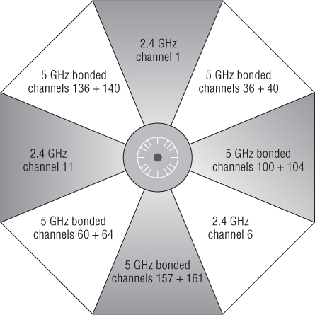
Figure 4.15 Static beamforming—indoor sectorized array
Dynamic Beamforming
Dynamic beamforming focuses the RF energy in a specific direction and in a particular shape. Like static beamforming, the direction and shape of the signal is focused, but unlike static beamforming, the radiation pattern of the signal can change on a frame-by-frame basis. This can provide the optimal power and signal for each station. As shown in Figure 4.16, dynamic beamforming uses an adaptive antenna array that maneuvers the beam in the direction of a targeted receiver. The technology is often referred to as smart antenna technology, or beamsteering. Currently, the only Wi-Fi vendor that offers dynamic beamforming capabilities in its access points is Ruckus Wireless. Dynamic beamforming capabilities are not available on the client side.
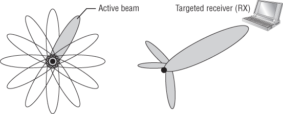
Figure 4.16 Dynamic beamforming—adaptive antenna array
Dynamic beamforming can focus a beam in the direction of an individual client for downstream unicast transmissions between an access point and the targeted client. However, any broadcast frames such as beacons are transmitted using an omnidirectional pattern so that the access point can communicate with all nearby client stations in all directions. Note that Figure 4.16 illustrates the concept; the actual beam is probably more like the signal pattern generated by the antenna in Figure 4.12.
Transmit Beamforming
Transmit beamforming (TxBF) is performed by transmitting multiple phase-shifted signals with the hope and intention that they will arrive in-phase at the location where the transmitter believes that the receiver is located. Unlike dynamic beamforming, TxBF does not change the antenna radiation pattern and an actual directional beam does not exist. In truth, transmit beamforming is not really an antenna technology; it is a digital signal processing technology on the transmitting device that duplicates the transmitted signal on more than one antenna to optimize a combined signal at the client. However, carefully controlling the phase of the signals transmitted from multiple antennas has the effect of improving gain, thus emulating a higher-gain unidirectional antenna. Transmit beamforming is all about adjusting the phase of the transmissions.
The 802.11n amendment defined two types of transmit beamforming, implicit TxBF and explicit TxBF. Implicit TxBF uses an implicit channel-sounding process to optimize the phase differentials between the transmit chains. Explicit TxBF requires feedback from the stations in order to determine the amount of phase-shift required for each signal. The 802.11ac amendment defines explicit TxBF, requiring the use of channel measurement frames, and both the transmitter and the receiver must support beamforming. 802.11ac will be discussed in greater detail in Chapter 19, “Very-High Throughput (VHT) and 802.11ac.”
Visual Line of Sight
When light travels from one point to another, it travels across what is perceived to be an unobstructed straight line, known as the visual line of sight (LOS). For all intents and purposes, it is a straight line, but because of the possibility of light refraction, diffraction, and reflection, there is a slight chance that it is not. If you have been outside on a summer day and looked across a hot parking lot at a stationary object, you may have noticed that, because of the heat rising from the pavement, the object that you were looking at seemed to be moving. This is an example of how visual LOS is sometimes altered slightly. When it comes to RF communications, visual LOS has no bearing on whether the RF transmission is successful.
RF Line of Sight
Point-to-point RF communication also needs to have an unobstructed line of sight between the two antennas. So, the first step for installing a point-to-point system is to make sure that, from the installation point of one of the antennas, you have a clear direct path to the other antenna. Unfortunately, for RF communications to work properly, this is not sufficient. An additional area around the visual LOS needs to remain clear of obstacles and obstructions. This area around the visual LOS is known as the Fresnel zone and is often referred to as RF line of sight.
Fresnel Zone
The Fresnel zone (pronounced FRUH-nel—the s is silent) is an imaginary, elongated, football-shaped area (American football) that surrounds the path of the visual LOS between two point-to-point antennas. Figure 4.17 shows an illustration of the Fresnel zone's football-like shape.
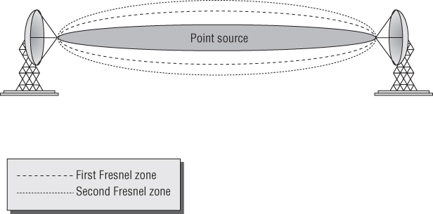
Figure 4.17 Fresnel zone
Theoretically, there are an infinite number of Fresnel zones, or concentric ellipsoids (the football shape), that surround the visual LOS. The closest ellipsoid is known as the first Fresnel zone, the next one is the second Fresnel zone, and so on, as depicted in Figure 4.17. For simplicity's sake, and because they are the most relevant for this section, only the first two Fresnel zones are displayed in the figure. The subsequent Fresnel zones have little effect on communications.
If the first Fresnel zone becomes even partly obstructed, the obstruction will negatively influence the integrity of the RF communication. In addition to the obvious reflection and scattering that can occur if there are obstructions between the two antennas, the RF signal can be diffracted or bent as it passes an obstruction of the Fresnel zone. This diffraction of the signal decreases the amount of RF energy that is received by the antenna and may even cause the communications link to fail.
Figure 4.18 illustrates a link that is 1 mile long. The top solid line is a straight line from the center of one antenna to the other. The dotted line shows 60 percent of the bottom half of the first Fresnel zone. The bottom solid line shows the bottom half of the first Fresnel zone. The trees are potential obstructions along the path.
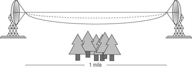
Figure 4.18 Fresnel zone clearances of 60 percent and 100 percent
Under no circumstances should you allow any object or objects to encroach more than 40 percent into the first Fresnel zone of an outdoor point-to-point bridge link. Anything more than 40 percent is likely to make the communications link unreliable. Even less than 40 percent obstruction is likely to impair the performance of the link. Therefore, we recommend that you do not allow any obstruction of the first Fresnel zone, particularly in wooded areas where the growth of trees may obstruct the Fresnel zone in the future.
The typical obstacles that you are likely to encounter are trees and buildings. It is important to periodically visually check your link to make sure that trees have not grown into the Fresnel zone or that buildings have not been constructed that encroach into the Fresnel zone. Do not forget that the Fresnel zone exists below, to the sides, and above the visual LOS. If the Fresnel zone does become obstructed, you will need to either move the antenna (usually raise it) or remove the obstacle (usually with a chain saw—just kidding).
To determine whether an obstacle is encroaching into the Fresnel zone, you need to be familiar with a few formulas that enable you to calculate its radius. Don't fret; you will not be tested on these formulas.
The first formula enables you to calculate the radius of the first Fresnel zone at the midpoint between the two antennas. This is the point where the Fresnel zone is the largest. This formula is as follows:
- D = distance of the link in miles
- F = transmitting frequency in GHz
This is the optimal clearance that you want along the signal path. Although this is the ideal radius, it is not always feasible. Therefore, the next formula will be very useful. It can be used to calculate the radius of the Fresnel zone that will enable you to have 60 percent of the Fresnel zone unobstructed. This is the minimum amount of clearance you need at the midpoint between the antennas. Here is this formula:
- D = distance of the link in miles
- F = transmitting frequency in GHz
Both of these formulas are useful, but in addition to their benefits, they have major shortcomings. These formulas calculate the radius of the Fresnel zone at the midpoint between the antennas. Since this is the point where the Fresnel zone is the largest, these numbers can be used to determine the minimum height the antennas need to be above the ground. You have to know this number, because if you place the antennas too low, the ground would encroach on the Fresnel zone and cause degradation to the communications. The problem is that if there is a known object somewhere other than the midpoint between the antennas, it is not possible to calculate the radius of the Fresnel zone at that point by using these equations. The following formula can be used to calculate the radius of any Fresnel zone at any point between the two antennas:
- N = which Fresnel zone you are calculating (usually 1 or 2)
- d1 = distance from one antenna to the location of the obstacle in miles
- d2 = distance from the obstacle to the other antenna in miles
- D = total distance between the antennas in miles (D = d1 + d2)
- F = frequency in GHz
Figure 4.19 shows a point-to-point communications link that is 10 miles long. There is an obstacle (tree) that is 3 miles away from one antenna and 40 feet tall. So, the values and the formula to calculate the radius of the Fresnel zone at a point 3 miles from the antenna are as follows:
- N = 1 (for first Fresnel zone)
- d1 = 3 miles
- d2 = 7 miles
- D = 10 miles
- F = 2.4 GHz
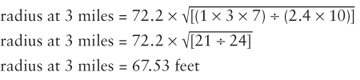
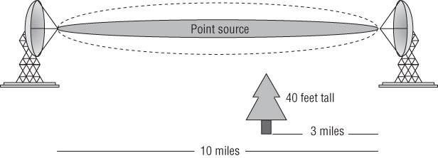
Figure 4.19 Point-to-point communication with potential obstacle
So, if the obstacle is 40 feet tall and the Fresnel zone at that point is 67.53 feet tall, the antennas need to be mounted at least 108 feet (40′ + 67.53′ = 107.53′; we rounded up) above the ground to have complete clearance. If we are willing to allow the obstruction to encroach up to 40 percent into the Fresnel zone, we need to keep 60 percent of the Fresnel zone clear. So 60 percent of 67.53 feet is 40.52 feet. The absolute minimum height of the antennas will need to be 81 feet (40′ + 40.52′ = 80.52′; again we rounded up). In the next section, you will learn that, because of the curvature of the earth, you will need to raise the antennas even higher to compensate for the earth's bulge.
When highly directional antennas are used, the beamwidth of the signal is smaller, causing a more focused signal to be transmitted. Many people think that a smaller beamwidth would decrease the size of the Fresnel zone. This is not the case. The size of the Fresnel zone is a function of the frequency being used and the distance of the link. Since the only variables in the formula are frequency and distance, the size of the Fresnel zone will be the same regardless of the antenna type or beamwidth. The first Fresnel zone is technically the area around the point source, where the waves are in phase with the point source signal. The second Fresnel zone is then the area beyond the first Fresnel zone, where the waves are out of phase with the point source signal. All of the odd-numbered Fresnel zones are in phase with the point source signal, and all of the even-numbered Fresnel zones are out of phase.
If an RF signal of the same frequency but out of phase with the primary signal intersects the primary signal, the out-of-phase signal will cause degradation or even cancellation of the primary signal (this was covered in Chapter 2 and demonstrated using the EMANIM software). One of the ways that an out-of-phase signal can intercept the primary signal is by reflection. It is, therefore, important to consider the second Fresnel zone when evaluating point-to-point communications. If the height of the antennas and the layout of the geography are such that the RF signal from the second Fresnel zone is reflected toward the receiving antenna, it can cause degradation of the link. Although this is not a common occurrence, the second Fresnel zone should be considered when planning or troubleshooting the connection, especially in flat, arid terrain, like a desert. You should also be cautious of metal surfaces or calm water along the Fresnel zone.
Please understand that the Fresnel zone is three-dimensional. Can something impede on the Fresnel zone from above? Although trees do not grow from the sky, a point-to-point bridge link could be shot under a railroad trestle or a freeway. In these rare situations, consideration would have to be given to proper clearance of the upper radius of the first Fresnel zone. A more common scenario would be the deployment of point-to-point links in an urban city environment. Very often building-to-building links must be shot between other buildings. In these situations, other buildings have the potential of impeding the side radiuses of the Fresnel zone.
Until now, all of the discussion about the Fresnel zone has related to point-to-point communications. The Fresnel zone exists in all RF communications; however, it is in outdoor point-to-point communications where it can cause the most problems. Indoor environments have so many walls and other obstacles where there is already so much reflection, refraction, diffraction, and scattering that the Fresnel zone is not likely to play a big part in the success or failure of the link.
Earth Bulge
When you are installing long-distance point-to-point RF communications, another variable that must be considered is the curvature of the earth, also known as the earth bulge. Because the landscape varies throughout the world, it is impossible to specify an exact distance for when the curvature of the earth will affect a communications link. The recommendation is that if the antennas are more than 7 miles away from each other, you should take into consideration the earth bulge, because after 7 miles, the earth itself begins to impede on the Fresnel zone. The following formula can be used to calculate the additional height that the antennas will need to be raised to compensate for the earth bulge:
- H = D2 ÷ 8
- H = height of the earth bulge in feet
- D = distance between the antennas in miles
You now have all of the pieces to estimate how high the antennas need to be installed. Remember, this is an estimate that is being calculated, because it is assumed that the terrain between the two antennas does not vary. You need to know or calculate the following three things:
- The 60 percent radius of the first Fresnel zone
- The height of the earth bulge
- The height of any obstacles that may encroach into the Fresnel zone, and the distance of those obstacles from the antenna
Taking these three pieces and adding them together gives you the following formula, which can be used to calculate the antenna height:
- H = obstacle height + earth bulge + Fresnel zone
- OB = obstacle height
- D = distance of the link in miles
- F = transmitting frequency in GHz
Figure 4.20 shows a point-to-point link that spans a distance of 12 miles. In the middle of this link is an office building that is 30 feet tall. A 2.4 GHz signal is being used to communicate between the two towers. Using the formula, we calculate that each of the antennas needs to be installed at least 96.4 feet above the ground:
- H = 30 + 18 + 48.4 = H = 96.4
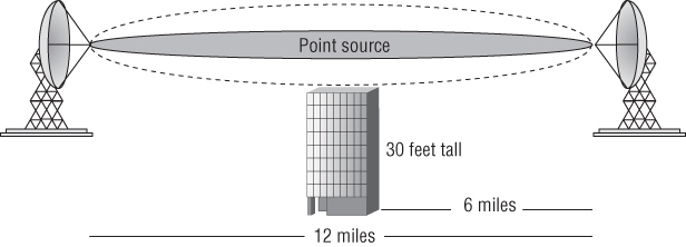
Figure 4.20 Calculating antenna height
Although these formulas are useful, the good news is that you do not need to know them for the test.
Antenna Polarization
Another consideration when installing antennas is antenna polarization. Although it is a lesser-known concern, it is extremely important for successful communications. Proper polarization alignment is vital when installing any type of antenna. As waves radiate from an antenna, the amplitude of the waves can oscillate either vertically or horizontally. It is important to have the polarization of the transmitting and receiving antennas oriented the same in order to receive the strongest possible signal. Whether the antennas are installed with horizontal or vertical polarization is usually irrelevant, as long as both antennas are aligned with the same polarization.
Polarization is not as important for indoor communications because the polarization of the RF signal often changes when it is reflected, which is a common occurrence indoors. Most access points use low-gain omnidirectional antennas, and they should be polarized vertically when mounted from the ceiling. Laptop manufacturers build antennas into the sides of the monitor. When the laptop monitor is in the upright position, the internal antennas are vertically polarized as well.
When aligning a point-to-point or point-to-multipoint bridge, proper polarization is extremely important. If the best received signal level (RSL) you receive when aligning the antennas is 15 dB to 20 dB less than your estimated RSL, there is a good chance you have cross-polarization. If this difference exists on only one side and the other has higher signal, you are likely aligned to a side lobe.
Antenna Diversity
Wireless networks, especially indoor networks, are prone to multipath signals. To help compensate for the effects of multipath, antenna diversity, also called spatial diversity, is commonly implemented in wireless networking equipment such as access points. Antenna diversity exists when an access point has two or more antennas with a receiver functioning together to minimize the negative effects of multipath.
Because the wavelengths of 802.11 wireless networks are less than 5 inches long, the antennas can be placed very near each other and still allow antenna diversity to be effective. When the access point senses an RF signal, it compares the signal that it is receiving on both antennas and uses whichever antenna has the higher signal strength to receive the frame of data. This sampling is performed on a frame-by-frame basis, choosing whichever antenna has the higher signal strength.
Most pre-802.11n radios use switched diversity. When receiving incoming transmissions, switched diversity listens with multiple antennas. Multiple copies of the same signal arrive at the receiver antennas with different amplitudes. The signal with the best amplitude is chosen, and the other signals are ignored. The AP will use one antenna as long as the signal is above a predefined signal level. If the signal degrades below the acceptable level, then the AP will use the signal received on the other antenna.
This method of listening for the best received signal is also known as receive diversity. Switched diversity is also used when transmitting, but only one antenna is used. The transmitter will transmit out of the diversity antenna where the best amplitude signal was last heard. The method of transmitting out of the antenna where the last best received signal was heard is known as transmit diversity.
Because the antennas are so close to each other, it is not uncommon to doubt that antenna diversity is actually beneficial. As you may recall from Chapter 3, the amount of RF signal that is received is often less than 0.00000001 milliwatts. At this level of signal, the slightest difference between the signals that each antenna receives can be significant. Other factors to remember are that the access point is often communicating with multiple client devices at different locations. These clients are not always stationary, thus further affecting the path of the RF signal.
The access point has to handle transmitting data differently than receiving data. When the access point needs to transmit data back to the client, it has no way of determining which antenna the client would receive from the best. An access point can handle transmitting data by using the antenna that it used most recently to receive the data. You will remember that this is often referred to as transmit diversity. Not all access points are equipped with this capability.
There are many kinds of antenna diversity. Laptops with internal cards usually have diversity antennas mounted inside the laptop monitor. Remember that because of the half-duplex nature of the RF medium, when antenna diversity is used only one antenna is operational at any given time. In other words, a radio card transmitting a frame with one antenna cannot be receiving a frame with the other antenna at the same time.
Multiple-Input, Multiple-Output
Multiple-input, multiple-output (MIMO) is another, more sophisticated form of antenna diversity. Unlike conventional antenna systems, where multipath propagation is an impairment, MIMO (pronounced MY-moh) systems take advantage of multipath. MIMO can safely be described as a wireless radio architecture that can receive or transmit using multiple antennas concurrently. Complex signal-processing techniques enable significant enhancements to reliability, range, and throughput in MIMO systems. These techniques send data by using multiple simultaneous RF signals, and the receiver then reconstructs the data from those signals.
802.11n and 802.11ac radios use MIMO technology. One of the key goals when installing a MIMO device is to make sure that each of the signals from the different radio chains travel with different signal polarization. This can be done by aligning or orienting the antennas so that the path that each signal travels is at least slightly different. This will help to introduce delay between the different MIMO signals, which will improve the ability for the MIMO receiver to process the different signals. Different types of MIMO antennas are discussed in the next section and MIMO technology is explored in much further detail in Chapter 18 and Chapter 19, as it is a key component of 802.11n and 802.11ac.
MIMO Antennas
With the need and desire to increase the throughput and capacity of wireless networks, the installation of 802.11n and 802.11ac access points has become the norm. 802.11n has become commonplace not only for indoor networks but also for outdoor networks and point-to-point networks. 802.11ac is quickly supplanting 802.11n networks indoors and will likely become commonplace in outdoor implementations. MIMO antenna selection and placement is important in each of these environments.
Indoor MIMO Antennas
There is usually not much decision making involved regarding the antennas on an indoor MIMO access point. Many of the new enterprise MIMO access points have the antennas integrated into the chassis of the access point, with no antennas protruding from the access point. If the antennas are not integrated in the access point chassis, the MIMO access point likely has three omnidirectional antennas directly attached to it. In some cases the antennas are detachable, allowing you to choose higher gain omnidirectional antennas.
When installing or configuring external MIMO antennas, some vendors require that they all be lined up parallel with each other. If the vendor does not specify this, then you should align them slightly off parallel with each other. One antenna should be aligned vertically, and the other two antennas should be tilted. How much the antennas should be tilted is a topic of much discussion. It is likely that with so many reflective surfaces indoors, the environment itself will provide the necessary multipath for the different signals. While this is likely, it may not be a bad idea to tilt the antennas slightly from an angle of about 15 degrees up to a maximum angle of about 30 degrees off of vertical. None of the antennas should be parallel with any of the other antennas. The goal of tilting the antennas is to help create multipath, but you do not want to change the coverage pattern of the antennas. It is important that all of the antennas are identical. As mentioned earlier, indoor MIMO antennas are often deployed in high-density environments.
Outdoor MIMO Antennas
Most outdoor MIMO access points currently have two antennas per radio, but three radio chain units are becoming more common. As with the indoor access points, multipath provides a benefit for successful and higher data rate communications with outdoor MIMO devices. This benefit may not be realized if the environment does not have reflective surfaces that induce multipath. Therefore, it is important to try to change the radiation path of the two or three antennas while maintaining the same range and coverage with all of the antennas. In the outdoor environment, achieving this goal requires more knowledge and technology than can usually be achieved by leaving the antenna choice and placement up to the designer or installer of the networks. Therefore, many of the access point and antenna manufacturers have designed both omnidirectional and directional MIMO antennas.
To distinguish the different radio chain signals from each other, the directional MIMO antennas incorporate two or three antenna elements within one physical antenna. With a two-element antenna, one of the elements is mounted with vertical polarization and the other with horizontal polarization. The antenna will have two connectors to connect it to the access point. If the access point that the antenna is being connected to is a multi-radio access point, the access point will have two antenna connectors for each radio. It is important to make sure that the two cables from the antenna are connected to the antenna jacks for the same radio. With a three-element antenna, typically two of the elements are mounted 90 degrees off of each other, and the third element is mounted 45 degrees off of the other two elements. The antenna will have three connectors to connect it to the access point. Again, if the access point has two radios, be careful which antenna jacks you use to connect the antenna.
To provide omnidirectional MIMO coverage with two radio chain APs, special pairs of omnidirectional antennas are available. Each pair is made up of an omnidirectional antenna with vertical polarization and a second omnidirectional antenna with horizontal polarization. It is a little strange using these antennas, because in the past with legacy non-802.11n access points, if two omnidirectional antennas were installed on an access point, it was important to purchase identical antennas. With outdoor MIMO omnidirectional antennas, the antennas are purchased as a set, but they are typically of different lengths and widths because of the different polarization that each antenna has. If you are not familiar with these new antenna pairs, you may think that you were shipped the wrong product, due to the antennas not looking the same. When trying to provide omnidirectional coverage using a three-radio-chain AP, special single chassis antennas have begun to appear. One particular type, known as a down-tilt antenna, is made up of three omnidirectional antenna elements, mounted within one antenna body. The antenna is typically mounted in a high location, mounted horizontally above the area of coverage, and is faced down at the floor or ground below. The horizontal coverage area is omnidirectional. The vertical coverage behaves like a typical omnidirectional antenna but with more vertical signal/coverage below the antenna than above.
Antenna Connection and Installation
In addition to the physical antenna being a vital component in the wireless network, the installation and connection of the antenna to the wireless transceiver is critical. If the antenna is not properly connected and installed, any benefit that the antenna introduces to the network can be instantly wiped out. Three key components associated with the proper installation of the antenna are voltage standing wave ratio (VSWR), signal loss, and the actual mounting of the antenna.
Voltage Standing Wave Ratio
Voltage standing wave ratio (VSWR) is a measurement of the change in impedances to an AC signal. Voltage standing waves exist because of impedance mismatches or variations between devices in an RF communications system. Impedance is a value of ohms of electrical resistance to an AC signal. A standard unit of measurement of electrical resistance is the ohm, named after German physicist Georg Ohm. When the transmitter generates the AC radio signal, the signal travels along the cable to the antenna. Some of this incident (or forward) energy is reflected back toward the transmitter because of impedance mismatch.
Mismatches may occur anywhere along the signal path but are usually due to abrupt impedance changes between the radio transmitter and cable and between the cable and the antenna. The amount of energy reflected depends on the level of mismatch between the transmitter, cable, and antenna. The ratio between the voltage of the reflected wave and the voltage of the incident wave, at the same point along the cable, is called the voltage reflection coefficient, usually designated by the Greek letter rho (ρ).
In an ideal system, where there are no mismatches (the impedance is the same everywhere), all of the incident energy will be delivered to the antenna (except for the resistive losses in the cable itself) and there will be no reflected energy. The cable is said to be matched, and the voltage reflection coefficient is exactly zero and the return loss, in dB, is infinite. Return loss is essentially the dB difference between the power sent to the antenna and the power reflected back, thus a higher value is better than a lower value. The combination of incident and reflected waves traveling back and forth along the cable creates a resulting standing wave pattern along the length of the line. The standing wave pattern is periodic (it repeats) and exhibits multiple peaks and troughs of voltage, current, and power.
VSWR is a numerical relationship between the measurement of the maximum voltage along the line (what is generated by the transmitter) and the measurement of the minimum voltage along the line (what is received by the antenna). VSWR is therefore a ratio of impedance mismatch, with 1:1 (no impedance) being optimal but unobtainable, and typical values range from 1.1:1 to as much as 1.5:1. VSWR military specs are 1.1:1.
When the transmitter, cable, and antenna impedances are matched (that is, there are no standing waves), the voltage along the cable will be constant. This matched cable is also referred to as a flat line because there are no peaks and troughs of voltage along the length of the cable. In this case, VSWR is 1:1. As the degree of mismatch increases, the VSWR increases with a corresponding decrease in the power delivered to the antenna. Table 4.2 shows this effect.
Table 4.2 Signal loss caused by VSWR
| VSWR | Radiated power | Lost power | Return loss | dB power loss |
| 1:1 | 100% | 0% | Infinite | 0 dB |
| 1.5:1 | 96% | 4% | 14 dB | Nearly 0 dB |
| 2:1 | 89% | 11% | 9.5 dB | < 1 dB |
| 6:1 | 50% | 50% | 2.9 dB | 3 dB |
If VSWR is large, this means that a large amount of voltage is being reflected back toward the transmitter. This of course means a decrease in power or amplitude (loss) of the signal that is supposed to be transmitted. This loss of forward amplitude is known as return loss and can be measured in dB. Additionally, the power that is being reflected back is then directed back into the transmitter. If the transmitter is not protected from excessive reflected power or large voltage peaks, it can overheat and fail. Understand that VSWR may cause decreased signal strength, erratic signal strength, or even transmitter failure.
The first thing that can be done to minimize VSWR is to make sure that the impedance of all of the wireless networking equipment is matched. Most wireless networking equipment has an impedance of 50 ohms; however, you should check the manuals to confirm this. When attaching the different components, make sure that all connectors are installed and crimped properly and that they are snugly tightened.
Signal Loss
When connecting an antenna to a transmitter, the main objective is to make sure that as much of the signal that is generated by the transmitter is received by the antenna to be transmitted. To achieve this, it is important to pay particular attention to the cables and connectors that connect the transmitter to the antenna. In the section “Antenna Accessories” later in this chapter, we review the cables, connectors, and many other components that are used when installing antennas. If inferior components are used, or if the components are not installed properly, the access point will most likely function below its optimal capability.
Antenna Mounting
As stated earlier in this chapter, proper installation of the antenna is one of the most important tasks to ensure an optimally functioning network. The following are key areas to be concerned with when installing antennas:
- Placement
- Mounting
- Appropriate use and environment
- Orientation and alignment
- Safety
- Maintenance
Placement
The proper placement of an antenna depends on the type of antenna. When installing omnidirectional antennas, it is important to place the antenna at the center of the area where you want coverage. Remember that lower-gain omnidirectional antennas provide broader vertical coverage, while higher-gain omnidirectional antennas provide wider but much flatter coverage. Be careful not to place high-gain omnidirectional antennas too high above the ground, because the narrow vertical coverage may cause the antenna to provide insufficient signal to clients located on the ground.
When installing directional antennas, make sure you know both the horizontal and vertical beamwidths so that you can properly aim the antennas. Also make sure that you are aware of the amount of gain the antenna is adding to the transmission. If the signal is too strong, it will overshoot the area that you are looking to provide coverage to. This can be a security risk, and you may want to decrease the amount of power that the transceiver is generating to reduce the coverage area, providing of course that this signal decrease does not compromise the performance of your link. Not only can it be a security risk, overshooting your coverage area is considered rude.
If you are installing an outdoor directional antenna, in addition to concerns regarding the horizontal and vertical beamwidths, make sure that you have correctly calculated the Fresnel zone and mounted the antenna accordingly.
Indoor Mounting Considerations
After deciding where to place the antenna, the next step is to decide how to mount it. There are numerous ways of mounting antennas indoors. Most access points have at least a couple of keyhole type mounts for hanging the access point off of a couple of screws on a wall. Most enterprise-class access points have mounting kits that allow you to mount the access point to a wall or ceiling. Many of these kits are designed to easily attach directly to the metal rails of a drop ceiling.
Two common concerns are aesthetics and security. Many organizations, particularly ones that provide hospitality-oriented services such as hotels and hospitals, are concerned about the aesthetics of the installation of the antennas. Specialty enclosures and ceiling tiles can help to hide the installation of the access points and antennas. Other organizations, particularly schools and public environments, are concerned with securing the access points and antennas from theft or vandalism. An access point can be locked in a secure enclosure, with a short cable connecting it to the antenna. There are even ceiling tiles with antennas built into them, invisible to anyone walking by. If security is a concern, mounting the antenna high on the wall or ceiling can also minimize unauthorized access.
If access points or antennas are installed below the ceiling, children or teens will often try to jump up and hit the antennas or throw things at them in an attempt to move them. This also needs to be considered when choosing locations to install antennas.
Outdoor Mounting Considerations
Many antennas, especially outdoor antennas, are mounted on masts or towers. It is common to use mounting clamps and U-bolts to attach the antennas to the masts. For mounting directional antennas, specially designed tilt-and-swivel mounting kits are available to make it easier to aim and secure the antenna. If the antenna is being installed in a windy location (and what rooftop or tower isn't windy?), make sure that you take into consideration wind load and properly secure the antenna.
Appropriate Use and Environment
Make sure that indoor access points and antennas are not used for outdoor communications. Outdoor access points and antennas are specifically built to withstand the wide range of temperatures that they may be exposed to. It is important to make sure that the environment where you are installing the equipment is within the operating temperature range of the access point and antennas. The extreme cold weather of northern Canada may be too cold for some equipment, whereas the extreme heat of the desert in Saudi Arabia may be too hot. Outdoor access points and antennas are also built to stand up to other elements, such as rain, snow, and fog. In addition to installing the proper devices, make sure that the mounts you use are designed for the environment in which you are installing the equipment.
With the expansion of wireless networking, it is becoming more common to not only install wireless devices in harsh environments but also to install them in potentially flammable or combustible environments, such as mines and oil rigs. Installation of access points and antennas in these environments requires special construction of the devices or the installation of the devices in special enclosures.
In the following sections, you will learn about four classification standards. The first two standards designate how a device will stand up to harsh conditions and the following two standards designate the environments in which a device is allowed to operate. These are just four examples of standards that exist and how they apply to equipment and environments. You will need to do research to determine if there are requirements to which you must (or should) adhere to in your country or region when installing equipment.
Ingress Protection Rating
The Ingress Protection Rating is sometimes referred to as the International Protection Rating and is commonly referred to as the IP Code (not to be confused with Internet Protocol, which is part of TCP/IP). The IP Rating system is published by the International Electrotechnical Commission (IEC). The IP Code is represented by the letters IP followed by two digits or a digit and one or two letters, such as IP66.
The first digit of the IP Code classifies the degree of protection that the device provides against the intrusion of solid objects, and the second digit classifies the degree of protection that the device provides against the intrusion of water. If no protection is provided for either of these classifications, the digit is replaced with the letter X.
The solids digit can be a value between 0 and 6 with protection ranging from no protection (0) up to dust tight (6). The liquids digit can be a value between 0 and 8, including, for example, no protection (0), dripping water (1), water splashing from any direction (4), powerful water jets (6), and immersion greater than one meter (8).
NEMA Enclosure Rating
The NEMA Enclosure Rating is published by the United States National Electrical Manufacturers Association (NEMA). The NEMA ratings are similar to the IP ratings, but the NEMA ratings also specify other features, such as corrosion resistance, gasket aging, and construction practices.
The NEMA enclosure types are defined in the NEMA Standards Publication 250-2008, “Enclosures for Electrical Equipment (1000 Volts Maximum).” This document defines the degree of protection from such things as solid foreign objects like dirt, dust, lint, and fibers along with the ingress of water, oil, and coolant. The rating for the NEMA enclosures is in the form of a number or a number followed by a letter, such as Type 2 or Type 12K.
ATEX Directives
There are two ATEX directives:
- ATEX 95 This pertains to equipment and protective systems that are intended to be used in potentially explosive atmospheres.
- ATEX 137 This pertains to the workplace and is intended to protect and improve the safety and health of workers at risk from explosive atmospheres.
Organizations in the European Union must follow these directives to protect employees. The ATEX directives inherits their name from the French title of the 94/9/EC directive: “Appareils destinés à être utilisés en ATmosphères EXplosibles.”
Employers must classify work areas where explosive atmospheres may exist into different zones. Areas can be classified for gas-vapor-mist environments or dust environments. These regulations apply to all equipment, whether mechanical or electrical, and are categorized for mining and surface industries.
National Electrical Code Hazardous Locations
The National Electrical Code (NEC) is a standard for the safe installation of electrical equipment and wiring. The document itself is not a legally binding document, but it can and has been adopted by many local and state governments in the United States, thus making it law in those places. A substantial part of the NEC discusses hazardous locations. The NEC classifies hazardous locations by type, condition, and nature. The hazardous location type is defined as follows:
- Class I—gas or vapor
- Class II—dust
- Class III—fibers and flyings
The type is further subdivided by the conditions of the hazardous location:
- Division 1—normal conditions (for example, a typical day at the loading dock)
- Division 2—abnormal conditions (same loading dock, but a container is leaking its contents)
A final classification defines a group for the hazardous substance, based on the nature of the substance. This value is represented by an uppercase letter ranging from A through G.
Orientation and Alignment
Before installing an antenna, make sure you read the manufacturer's recommendations for mounting it. This suggestion is particularly important when installing directional antennas. Since directional antennas may have different horizontal and vertical beamwidths, and because directional antennas can be installed with different polarization, proper orientation can make the difference between being able to communicate or not:
- Make sure that the antenna polarization is consistent on both ends of a directional link.
- Decide on the mounting technique and ensure that it is compatible with the mounting location.
- Align the antennas.
Remember that you need to align both the direction of the antenna and its vertical tilt.
- Weatherproof the cables and connectors and secure them from movement.
- Document and photograph each installation of the access point and antennas. This can help you troubleshoot problems in the future and allows you to more easily determine if there has been movement in the installation or antenna alignment.
As mentioned earlier in this chapter, with the transition to 802.11n, 802.11ac, and MIMO, special two radio chain, outdoor omnidirectional MIMO antennas have been designed to be installed as pairs, with one antenna generating a signal with vertical polarization and the other generating a signal with horizontal polarization.
Safety
We can't emphasize enough the importance of being careful when installing antennas. Most of the time, the installation of an antenna requires climbing ladders, towers, or rooftops. Gravity and wind have a way of making an installation difficult for both the climber and the people below helping.
Plan the installation before you begin, making sure you have all of the tools and equipment that you will need to install the antenna. Unplanned stoppages of the installation and relaying forgotten equipment up and down the ladder add to the risk of injury.
Be careful when working with your antenna or near other antennas. Highly directional antennas are focusing high concentrations of RF energy. This large amount of energy can be dangerous to your health. Do not power on your antenna while you are working on it, and do not stand in front of other antennas that are near where you are installing your antenna. You probably do not know the frequency or power output of these other antenna systems, nor the potential health risks that you might be exposed to.
When installing antennas (or any device) on ceilings, rafters, or masts, make sure they are properly secured. Even a 1-pound antenna can be deadly if it falls from the rafters of a warehouse.
If you will be installing antennas as part of your job, we recommend that you take an RF health and safety course. In the United States, these courses will teach you the FCC and the US Department of Labor Occupational Safety and Health Administration (OSHA) regulations and how to be safe and compliant with the standards. Similar courses can be found in many other countries around the world. We suggest looking for courses that are appropriate to your country or region.
If you need an antenna installed on any elevated structure, such as a pole, tower, or even a roof, consider hiring a professional installer. Professional climbers and installers are trained and, in some places, certified to perform these types of installations. In addition to the training, they have the necessary safety equipment and proper insurance for the job.
If you are planning to install wireless equipment as a profession, you should develop a safety policy that is approved by your local occupational safety representative. You should also receive certified training on climbing safety in addition to RF safety training. First aid and CPR training are also highly recommended.
Maintenance
There are two types of maintenance: preventive and diagnostic. When installing an antenna, it is important to prevent problems from occurring in the future. This seems like simple advice, but since antennas are often difficult to get to after they have been installed, it is especially prudent advice. Two key problems that can be minimized with proper preventative measures are wind damage and water damage. When installing the antenna, make sure all of the nuts, bolts, screws, and so on are installed and tightened properly. Also make sure all the cables are properly secured so that they are not thrashed about by the wind.
To help prevent water damage, cold-shrink tubing or coaxial sealant can be used to minimize the risk of water getting into the cable or connectors. Another common method is a combination of electrical tape and mastic, installed in layers to provide a completely watertight installation. If mastic is used, be sure to first tightly wrap the connection with electrical tape before applying the mastic. If the connection ever needs to be disconnected and reattached, it will be virtually impossible to remove the mastic if it has been applied directly to the connector.
Another cabling technique is the drip loop. To create a drip loop, when a cable is run down to a connector, run the cable down below the connector and then loop it up to the connector, creating a small loop or “U” of cable below the connector. Drip loops are also used when a cable is run into a building or structure. A drip loop prevents water from flowing down the cable and onto a connector or into the hole where a cable enters the building. Any water that is flowing down the cable will continue to the bottom of the loop and then drip off.
Antennas are typically installed and forgotten about until they break. It is advisable to periodically perform a visual inspection of the antenna and, if needed, verify its status with the installation documentation. If the antenna is not easily accessible, a pair of binoculars or a camera with a very high zoom lens can make this a simple task.
Antenna Accessories
In Chapter 3, we introduced the components of RF communications. In that chapter, the main components were reviewed; however, there are other components that are either not as significant or not always installed as part of the communications link. Important specifications for all antenna accessories include frequency response, impedance, VSWR, maximum input power, and insertion loss. In the following sections we will discuss some of these components and accessories.
Cables
Improper installation or selection of cables can detrimentally affect the RF communications more than just about any other component or outside influence. It is important to remember this fact when installing antenna cables. The following list addresses some concerns when selecting and installing cables:
-
Make sure you select the correct cable.
The impedance of the cable needs to match the impedance of the antenna and transceiver. If there is an impedance mismatch, the return loss from VSWR will affect the link.
-
Make sure the cable you select will support the frequencies that you will be using.
Typically, cable manufacturers list cutoff frequencies, which are the lowest and highest frequencies that the cable supports. This is often referred to as frequency response. For instance, LMR cable is a popular brand of coaxial cable used in RF communications. LMR-1200 will not work with 5 GHz transmissions. LMR-900 is the highest you can use. However, you can use LMR-1200 for 2.4 GHz operations.
Cables introduce signal loss into the communications link.
To determine how much loss, cable vendors provide charts or calculators to assist you. Figure 4.21 is an attenuation chart for LMR cable produced by Times Microwave Systems. The left side of the chart lists different types of LMR cable. The farther you move down the list, the better the cable is. The better cable is typically thicker, stiffer, more difficult to work with, and of course, more expensive. The chart shows how much decibel loss the cable will add to the communications link per 100 feet of cable. The column headers list the frequencies that may be used with the cable. For example, 100 feet of LMR-400 cable used on a 2.5 GHz network (2,500 MHz) would decrease the signal by 6.8 dB.
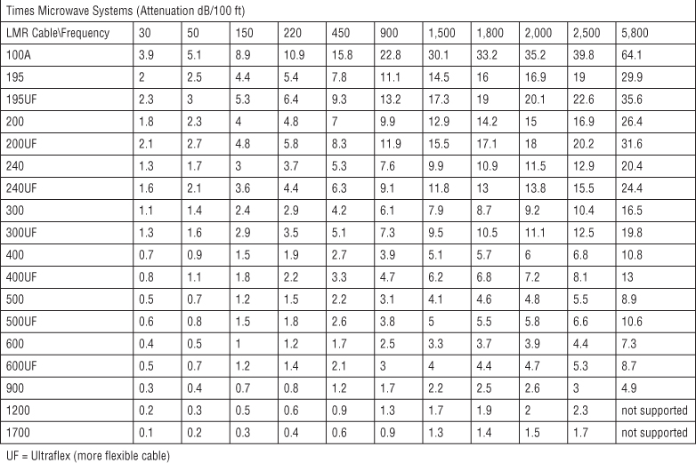
Figure 4.21 Coaxial cable attenuation
- Attenuation increases with frequency. If you convert from a 2.4 GHz WLAN to a 5 GHz WLAN, the loss caused by the cable will be greater.
-
Either purchase the cables precut and preinstalled with the connectors or hire a professional cabler to install the connections (unless you are a professional cabler).
Improperly installed connectors will add more loss to the communications link, which can nullify the extra money you spend for the better-quality cable. It can also introduce return loss in the cable due to reflections.
Connectors
Many types of connectors are used to connect antennas to 802.11 equipment. Part of the reason for this is that the FCC Report & Order 04-165 requires that amplifiers have either unique connectors or electronic identification systems to prevent the use of noncertified antennas. This requirement was created to prevent people from connecting higher-gain antennas, either intentionally or unintentionally, to a transceiver. An unauthorized high-gain antenna could exceed the maximum equivalent isotropically radiated power (EIRP) that is allowed by the FCC or other regulatory body.
In response to this regulation, cable manufacturers sell pigtail adapter cables. These pigtail cables are usually short segments of cable (typically about 2 feet long) with different connectors on each end. They act as adapters, changing the connector and allowing a different antenna to be used.
Many of the same principles of cables apply to the connectors as well as many of the other accessories. RF connectors need to be of the correct impedance to match the other RF equipment. They also support specific ranges of frequencies. The connectors add signal loss to the RF link, and lower-quality connectors are more likely to cause connection or VSWR problems. RF connectors on average add about 1/2 dB of insertion loss.
Splitters
Splitters are also known as signal splitters, RF splitters, power splitters, and power dividers. A splitter takes an RF signal and divides it into two or more separate signals. Only in an unusually special or unique situation would you need to use an RF splitter. One such situation would be if you were connecting sector antennas to one transceiver. If you had three 120-degree antennas aimed away from a central point to provide 360-degree coverage, you could connect each antenna to its own transceiver, or you could use a three-way splitter and equal-length cables to connect the antennas to a single transceiver. When you install a splitter in this type of configuration, not only will the signal be degraded because it is being split three times (known as through loss), but also each connector will add its own insertion loss to the signal. There are so many variables and potential problems with this configuration that we recommend this type of installation be attempted only by a very RF-knowledgeable person and only for temporary installations.
A more practical, but again rare, use of a splitter is to monitor the power that is being transmitted. The splitter can be connected to the transceiver and then split to the antenna and a power meter. This approach would enable you to actively monitor the power that is being sent to the antenna.
Amplifiers
An RF amplifier takes the signal that is generated by the transceiver, increases it, and sends it to the antenna. Unlike the antenna providing an increase in gain by focusing the signal, an amplifier provides an overall increase in power by adding electrical energy to the signal, which is referred to as active gain.
Amplifiers can be purchased as either unidirectional or bidirectional devices. Unidirectional amplifiers perform the amplification in only one direction, either when transmitting or when receiving. Bidirectional amplifiers perform the amplification in both directions.
The amplifier's increase in power is created using one of two methods:
- Fixed-Gain With the fixed-gain method, the output of the transceiver is increased by the amount of the amplifier.
- Fixed-Output A fixed-output amplifier does not add to the output of the transceiver. It simply generates a signal equal to the output of the amplifier regardless of the power generated by the transceiver.
Since most regulatory bodies have a maximum power regulation of 1 watt or less at the intentional radiator (IR), the main purpose of using amplifiers is to compensate for cable loss as opposed to boosting the signal for range. Therefore, when installing an amplifier, install it as close to the antenna as possible. Because the antenna cable adds loss to the signal, the shorter antenna cable will produce less loss and allow more signal to the antenna.
Additionally, it is important to note that an amplifier increases noise as well as signal strength. It is not uncommon for an amplifier to raise the noise floor by 10 dB or more.
Attenuators
In some situations, it may be necessary to decrease the amount of signal that is radiating from the antenna. In some instances, even the lowest power setting of the transceiver may generate more signal than you want. In this situation, you can add a fixed-loss or a variable-loss attenuator. Attenuators are typically small devices about the size of a C-cell battery, with cable connectors on both sides. Attenuators absorb energy, decreasing the signal as it travels through. Fixed-loss attenuators provide a set amount of dB loss. A variable-loss attenuator has a dial or switch configuration on it that enables you to adjust the amount of energy that is absorbed.
Variable-loss attenuators are often used during outdoor site surveys to simulate loss caused by various grades of cabling and different cable lengths. Another interesting use of a variable attenuator is to test the actual fade margin on a point-to-point link. By gradually increasing the attenuation until there is no more link, you can use that number to determine the actual fade margin of the link.
Lightning Arrestors
The purpose of a lightning arrestor is to redirect (shunt) transient currents caused by nearby lightning strikes or ambient static away from your electronic equipment and into the ground. Lightning arrestors are used to protect electronic equipment from the sudden surge of power that a nearby lightning strike or static buildup can cause. You may have noticed the use of the phrase nearby lightning strike. This wording is used because lightning arrestors are not capable of protecting against a direct lightning strike. Lightning arrestors can typically protect against surges of up to 5,000 amperes at up to 50 volts. The IEEE specifies that lightning arrestors should be capable of redirecting the transient current in less than 8 microseconds. Most lightning arrestors are capable of doing it in less than 2 microseconds.
The lightning arrestor is installed between the transceiver and the antenna. Any devices that are installed between the lightning arrestor and the antenna will not be protected by the lightning arrestor. Therefore, the lightning arrestor is typically placed closer to the antenna, with all other communications devices (amplifiers, attenuators, etc.) installed between the lightning arrestor and the transceiver. Figure 4.22 shows a properly grounded radio, cabling, and antenna. After a lightning arrestor has performed its job by protecting the equipment from an electrical surge, it will have to be replaced, or it may have a replaceable gas discharge tube (like a fuse). Most installations place the lightning arrestor at the egress to the building. Cable grounding kits can be installed near the antenna and at every 100 feet.

Figure 4.22 Installation of lightning protection equipment
Fiber-optic cable can also be used to provide additional lightning protection. A short piece of fiber-optic cable can be inserted into the Ethernet cable that connects the wireless bridge to the rest of the network. Ethernet-to-fiber adapters, known as transceivers, convert the electrical Ethernet signal to a light-based fiber signal and then back to Ethernet. Because fiber-optic cable is constructed of glass and it uses light and not electricity to transmit data, it does not conduct electricity. It is important to make sure that the power supply for the adapters is protected as well.
The fiber-optic cable acts as a kind of safety net should the lightning arrestor fail due to a much higher transient current or even a direct lightning strike. Realize that if there is a direct lightning strike to the antenna, you can plan on replacing all the components from the fiber-optic cable to the antenna. Furthermore, a direct lightning strike may also arc over the fiber link and still cause damage to equipment on the opposite side of the fiber link. Grounding the RF cables as well can help prevent this from happening.
Grounding Rods and Wires
When lightning strikes an object, it is looking for the path of least resistance, or more specifically, the path of least impedance. This is where lightning protection and grounding equipment come into play. A grounding system, which is made up of a grounding rod and wires, provides a low-impedance path to the ground. This low-impedance path is installed to encourage the lightning to travel through it instead of through your expensive electronic equipment.
Grounding rods and wires are also used to create what is referred to as a common ground. One way of creating a common ground is to drive a copper rod into the ground and connect your electrical and electronic equipment to this rod by using wires or straps (grounding wires). The grounding rod should be at least 6 feet long and should be fully driven into the ground, leaving enough of the rod accessible to attach the ground wires to it. By creating a common ground, you have created a path of least impedance for all of your equipment should lightning cause an electrical surge.
On tower structures, a grounding rod should be placed off of each leg with a No. 2 tinned copper wire. These connections should be exothermically welded to the tower legs. A No. 2 tinned copper wire should also form a ring around the grounding rods, as illustrated in Figure 4.23. The dashed lines are No. 2 tinned copper wire and the circles are grounding rods. Ice bridges and building grounds should also be bonded to this ring to provide equal grounding potentials.
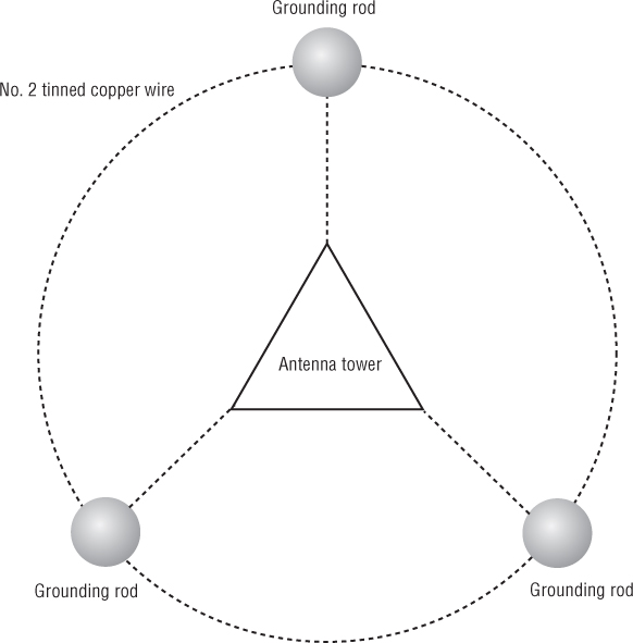
Figure 4.23 Grounding ring
Regulatory Compliance
In Chapter 3, you learned about the RF components along with the concepts of intentional radiator (IR) and equivalent isotropically radiated power (EIRP). In this chapter you learned about antennas and the many aspects of antenna operations and installation. Although there are many antenna, cabling, and component options when you are configuring a wireless network, the reality of it is that you are typically limited as to your antenna choices because of regulatory compliance. Although each regulatory body operates independently, there are similarities between how these organizations operate and certify equipment. This section will briefly explain the process in the United States, as regulated by the FCC.
In order for an access point manufacturer to sell its product within a country or region, it must prove that its product operates within the rules of the relevant regulatory domain, such as the FCC. The FCC creates documents that specify the rules that must be followed by the manufacturer, also referred to as the responsible party or the grant holder. The manufacturer will send its equipment to be tested by the regulatory body or an authorized testing organization, who will perform the compliance testing on the equipment. If the equipment passes the testing, the device will ultimately be issued an ID number and a Grant of Certification.
Most people are not familiar with this process and do not realize that when the company sends its product to be tested, what is submitted is the complete system that the manufacturer will market and sell as the product, which includes the intentional radiator (AP), any cabling and connectors, and the antenna or antennas that it wants to be able to use with the AP. Most companies will have their AP certified with a grouping of antennas that provide different gain and beamwidth characteristics.
An intentional radiator can be operated only with an antenna with which it is authorized. The FCC does allow an antenna to be substituted with a different one, providing two key conditions are met:
- The gain of the new antenna must be the same or lower than the antenna that the system was certified with.
- The new antenna must be of the same type, which means that the antenna must have the same in-band and out-of-band characteristics.
The gain of an antenna is easily identified and provided with most antennas, so the first criteria is relatively simple to meet. However, meeting the second criteria—for example, determining if one antenna is of the same type as another—requires verifying both the in-band and out-of-band characteristics of the antenna. How a new antenna will perform as part of a combined system for out-of-band requirements is very difficult to predict from datasheet information alone. The out-of-band requirements typically include spurious emissions limits over a very wide frequency range (9 KHz to 300 GHz), band edge emissions (a mask- type requirement), limits on harmonics generated, and very low limits on noise in specific restricted bands. Verifying a new antenna against all of these “out-of-band” requirements could require testing as extensive as the original certification testing itself. Therefore, if you wanted to replace your antenna with an antenna from a third-party manufacturer and wished to claim compliance of the resulting system, you could be asked to provide evidence that the combined system still passes all of these conditions with the new antenna. It is the manufacturer, or grant holder, who is responsible for adhering to the rules of the regulatory domain. Violation of regulatory domain rules could result in a manufacturer being fined or even denied the right to sell its product within the country or region where the violation occurred. Therefore, most manufacturers will not sell or support an antenna that is not on their list of approved antennas.
Summary
This chapter focused on RF signal and antenna concepts. The antenna is a key component of successful RF communications. Four types of antennas are used with 802.11 networks:
- Omnidirectional (dipole, collinear)
- Semidirectional (patch, panel, Yagi)
- Highly directional (parabolic dish, grid)
- Sector
The antenna types produce different signal patterns, which can be viewed on azimuth and elevation charts.
This chapter also reviewed some of the key concerns when installing point-to-point communications:
- Visual LOS
- RF LOS
- Fresnel zone
- Earth bulge
- Antenna polarization
The final section of this chapter covered VSWR and antenna mounting issues, along with antenna accessories and their roles.
Exam Essentials
- Know the different categories and types of antennas, how they radiate signals, and what type of environment they are used in. Make sure you know the three main categories of antennas and the different types of antennas. Know the similarities and differences between them, and understand when and why you would use one antenna over another. Make sure that you understand azimuth and elevation charts, beamwidth, antenna polarization, and antenna diversity.
- Fully understand the Fresnel zone. Make sure you understand all the issues and variables involved with installing point-to-point communications. You are not required to memorize the Fresnel zone or earth bulge formulas; however, you will need to know the principles regarding these topics and when and why you would use the formulas.
- Understand the concerns associated with connecting and installing antennas and the antenna accessories. Every cable, connector, and device between the transceiver and the antenna affects the signal that gets radiated from the antenna. Understand which devices provide gain and which provide loss. Understand what VSWR is and what values are good or bad. Know the different antenna accessories, what they do, and why and when you would use them.
Review Questions
- Which of the following refers to the polar chart of an antenna as viewed from above the antenna? (Choose all that apply)
- Horizontal view
- Vertical view
- H-plane
- E-plane
- Elevation chart
- Azimuth chart
- The azimuth chart represents a view of an antenna's radiation pattern from which direction?
- Top
- Side
- Front
- Both top and side
- What is the definition of the horizontal beamwidth of an antenna?
- The measurement of the angle of the main lobe as represented on the azimuth chart.
- The distance between the two points on the horizontal axis where the signal decreases by a third. This distance is measured in degrees.
- The distance between the two –3 dB power points on the horizontal axis, measured in degrees.
- The distance between the peak power and the point where the signal decreases by half. This distance is measured in degrees.
- Which antennas are highly directional? (Choose all that apply.)
- Omni
- Patch
- Panel
- Parabolic dish
- Grid
- Sector
- Semidirectional antennas are often used for which of the following purposes? (Choose all that apply.)
- Providing short-distance point-to-point communications
- Providing long-distance point-to-point communications
- Providing unidirectional coverage from an access point to clients in an indoor environment
- Reducing reflections and the negative effects of multipath
- The Fresnel zone should not be blocked by more than what percentage to maintain a reliable communications link?
- 20 percent
- 40 percent
- 50 percent
- 60 percent
- The size of the Fresnel zone is controlled by what factors? (Choose all that apply.)
- Antenna beamwidth
- RF line of sight
- Distance
- Frequency
- When a long-distance point-to-point link is installed, earth bulge should be considered beyond what distance?
- 5 miles
- 7 miles
- 10 miles
- 30 miles
- A network administrator replaced some coaxial cabling used in an outdoor bridge deployment after water damaged the cabling. After replacing the cabling, the network administrator noticed that the EIRP increased drastically and is possibly violating the maximum EIRP power regulation mandate. What are the possible causes of the increased amplitude? (Choose all that apply.)
- The administrator installed a shorter cable.
- The administrator installed a lower-grade cable.
- The administrator installed a higher-grade cable.
- The administrator installed a longer cable.
- The administrator used a different-color cable.
- Which of the following are true for antenna diversity used by 802.11a/b/g access points? (Choose all that apply.)
- The transceiver combines the signal from both antennas to provide better coverage.
- Transceivers can transmit from both antennas at the same time.
- The transceiver samples both antennas and chooses the best received signal from one antenna.
- Transceivers can transmit from only one of the antennas at a time.
- To establish a 4-mile point-to-point bridge link in the 2.4 GHz ISM band, what factors should be taken under consideration? (Choose all that apply.)
- Fresnel zone with 40 percent or less blockage
- Earth bulge calculations
- Minimum of 16 dBi of passive gain
- Proper choice of semidirectional antennas
- Proper choice of highly directional antennas
- The ratio between the maximum peak voltage and minimum voltage on a line is known as what?
- Signal flux
- Return loss
- VSWR
- Signal incidents
- What are some of the possible negative effects of an impendence mismatch? (Choose all that apply.)
- Voltage reflection
- Blockage of the Fresnel zone
- Erratic signal strength
- Decreased signal amplitude
- Amplifier/transmitter failure
- When determining the mounting height of a long-distance point-to-point antenna, which of the following needs to be considered? (Choose all that apply.)
- Frequency
- Distance
- Visual line of sight
- Earth bulge
- Antenna beamwidth
- RF line of sight
- Which of the following are true about cables? (Choose all that apply.)
- They cause impedance on the signal.
- They work regardless of the frequency.
- Attenuation decreases as frequency increases.
- They add loss to the signal.
- Amplifiers can be purchased with which of the following features? (Choose all that apply.)
- Bidirectional amplification
- Unidirectional amplification
- Fixed gain
- Fixed output
- The signal between the transceiver and the antenna will be reduced by which of the following methods? (Choose all that apply.)
- Adding an attenuator
- Increasing the length of the cable
- Shortening the length of the cable
- Using cheaper-quality cable
- Lightning arrestors will defend against which of the following?
- Direct lightning strikes
- Power surges
- Transient currents
- Improper common grounding
- The radius of the second Fresnel zone is _____. (Choose all that apply.)
- The area where the signal is out of phase with the point source
- The area where the signal is in phase with the point source
- Smaller than the first Fresnel zone
- Larger than the first Fresnel zone
- While aligning a directional antenna, you notice that the signal drops as you turn the antenna away from the other antenna, but then it increases a little. This increase in signal is cause by what?
- Signal reflection
- Frequency harmonic
- Side band
- Side lobe