Chapter 6
Wireless Networks and Spread Spectrum Technologies
In this chapter, you will learn about the following:
 Industrial, Scientific, and Medical bands (ISM)
- 900 MHz ISM band
- 2.4 GHz ISM band
- 5.8 GHz ISM band
- Unlicensed National Information Infrastructure bands (U-NII)
- U-NII-1 (lower band)
- U-NII-2 (middle band)
- U-NII-2 Extended
- U-NII-3 (upper band)
- Future U-NII bands
- 3.6 GHz band
- 4.9 GHz band
- Future Wi-Fi frequencies
- 60 GHz
- White-Fi
- Narrowband and spread spectrum
- Multipath interference
- Frequency hopping spread spectrum (FHSS)
- Hopping sequence
- Dwell time
- Hop time
- Modulation
- Direct sequence spread spectrum (DSSS)
- DSSS data encoding
- Modulation
- Packet Binary Convolutional Code (PBCC)
- Orthogonal Frequency Division Multiplexing (OFDM)
- Convolutional coding
- Modulation
- 2.4 GHz channels
- 5 GHz channels
- Adjacent, nonadjacent, and overlapping channels
- Throughput vs. bandwidth
- Communication resilience
In this chapter, you will learn about the different spread spectrum transmission technologies and frequency ranges that are supported by the 802.11 standard and amendments. You will learn how these frequencies are divided into different channels and some of the proper and improper ways of using the channels. Additionally, you will learn about the various types of spread spectrum technologies. You will also learn about Orthogonal Frequency Division Multiplexing (OFDM) and the similarities and differences between OFDM and spread spectrum.
Throughout this chapter are many references to FCC specifications and regulations. The CWNA exam does not test you on any regulatory domain–specific information. Any FCC references are strictly provided to help you understand the technology better. It is important to realize that similarities often exist between the regulations of different regulatory domains. Therefore, understanding the rules of another country's regulatory domain can help you interpret the rules of your regulatory domain.
Industrial, Scientific, and Medical Bands
The IEEE 802.11 standard and the subsequent 802.11b, 802.11g, and 802.11n amendments all define communications in the frequency range between 2.4 GHz and 2.4835 GHz. This frequency range is one of three frequency ranges known as the industrial, scientific, and medical (ISM) bands. The frequency ranges of the ISM bands are as follows:
- 902 MHz – 928 MHz (26 MHz wide)
- 2.4 GHz – 2.5 GHz (100 MHz wide)
- 5.725 GHz – 5.875 GHz (150 MHz wide)
The ISM bands are defined by the ITU Telecommunication Standardization Sector (ITU-T) in S5.138 and S5.150 of the Radio Regulations. Although the FCC governs the use of the ISM bands defined by the ITU-T in the United States, their usage in other countries may be different because of local regulations. The 900 MHz band is known as the industrial band, the 2.4 GHz band is known as the scientific band, and the 5.8 GHz band is known as the medical band.
Note that all three of these bands are license-free bands, and there are no restrictions on what types of equipment can be used in any of them. For example, a radio used in medical equipment can be used in the 900 MHz industrial band.
900 MHz ISM Band
The 900 MHz ISM band is 26 MHz wide and spans from 902 MHz to 928 MHz. In the past, this band was used for wireless networking. However, most wireless networks now use higher frequencies, which are capable of faster throughput.
Another factor limiting the use of the 900 MHz ISM band is that in many parts of the world, part of the 900 MHz frequency range has already been allocated to the Global System for Mobile Communications (GSM) for use by mobile phones. Although the 900 MHz ISM band is rarely used for networking, many products such as baby monitors, wireless home telephones, and wireless headphones use this frequency range.
802.11 radios do not operate in the 900 MHz ISM band, but many older legacy deployments of wireless networking did operate in this band. Some vendors still manufacture non-802.11 wireless networking devices that operate in the 900 MHz ISM band. This is a particularly popular frequency that is used for wireless ISPs because of its superior foliage penetration over the 2.4 GHz and 5 GHz frequency ranges.
2.4 GHz ISM Band
The 2.4 GHz ISM band is the most common band used for wireless networking communications. The 2.4 GHz ISM band is 100 MHz wide and spans from 2.4 GHz to 2.5 GHz. Use of the 2.4 GHz ISM for wireless LANs is defined by the IEEE in the 802.11-2012 standard. Even though most of the current 802.11 radio chipsets now include 5 GHz capabilities, the 2.4 GHz ISM band has been the primary band that is used by Wi-Fi devices, often making this band extremely overcrowded. The following wireless radios use this band:
- 802.11 (FHSS radios or DSSS radios)
- 802.11b (HR-DSSS radios)
- 802.11g (ERP radios)
- 802.11n (HT radios)
In addition to being used by 802.11 WLAN equipment, the 2.4 GHz ISM band is also used by microwave ovens, cordless home telephones, baby monitors, and wireless video cameras. The 2.4 GHz ISM band is heavily used, and one of the big disadvantages of using 802.11b/g/n 2.4 GHz radios is the potential for interference.
Please keep in mind that not every country's RF regulatory body will allow for transmissions across the entire 2.4 GHz – 2.5 GHz ISM band. The IEEE 802.11-2012 standard allows for WLAN transmissions in this band across 14 channels. However, each country can determine which channels can be used. A discussion of all the 2.4 GHz channels occurs later in this chapter.
5.8 GHz ISM Band
The 5.8 GHz ISM band is 150 MHz wide and spans from 5.725 GHz to 5.875 GHz. As with the other ISM bands, the 5.8 GHz ISM band is used by many of the same types of consumer products: baby monitors, cordless telephones, and cameras. It is not uncommon for novices to confuse the 5.8 GHz ISM band with the U-NII-3 band, which spans from 5.725 GHz to 5.85 GHz. Both unlicensed bands span the same frequency space. However, the 5.8 GHz ISM band is 25 MHz larger.
The IEEE 802.11a amendment (now part of 802.11-2012 standard) states that “the OFDM PHY shall operate in the 5 GHz band, as allocated by a regulatory body in its operational region.” Most countries allow for OFDM transmissions in channels of the various U-NII bands, which are discussed in this chapter. The United States has also always allowed OFDM transmissions on channel 165, which until April of 2014, resided in the 5.8 GHz ISM band. Historically, channel 165 has been sparsely used. In April of 2014, the U-NII-3 band was expanded to include channel 165.
From the perspective of Wi-Fi channels, the 5.8 GHz ISM band is no longer relevant, however, many of the consumer devices that operate in the 5.8 GHz ISM band can cause RF interference with 802.11 radios that transmit in the U-NII-3 band.
Unlicensed National Information Infrastructure Bands
The IEEE 802.11a amendment designated WLAN transmissions within the frequency space of the three 5 GHz bands, each with four channels. These frequency ranges are known as the Unlicensed National Information Infrastructure (U-NII) bands. The 802.11a amendment defined three groupings, or bands, of U-NII frequencies, often known as the lower, middle, and upper U-NII bands. These three bands are typically designated as U-NII-1 (lower), U-NII-2 (middle), and U-NII-3 (upper).
When the 802.11h amendment was ratified, the IEEE designated more frequency space for WLAN transmissions. This frequency space, which consists of 12 additional channels, is often referred to as U-NII-2 Extended.
Wi-Fi radios that currently transmit in the 5 GHz U-NII bands include radios that use the following technologies:
- 802.11a (OFDM radios)
- 802.11n (HT radios)
- 802.11ac (VHT radios)
Keep in mind that not every country's RF regulatory body will allow for transmissions in all these bands. The IEEE 802.11-2012 standard allows for WLAN transmissions in all four of the bands across 25 channels. However, each country may be different due to different channel and power regulations. A more detailed discussion of all the 5 GHz channels occurs later in this chapter.
U-NII-1 (Lower Band)
U-NII-1, the lower U-NII band, is 100 MHz wide and spans from 5.150 GHz to 5.250 GHz. A total of four 20 MHz 802.11 channels reside in the U-NII-1 band. In the past, the U-NII-1 band was restricted by the FCC for indoor use only in the United States. As of April 2014, the FCC lifted this restriction. Prior to 2004, the FCC required that all U-NII-1-capable devices have permanently attached antennas. This meant that any 802.11a device that supported U-NII-1 could not have a detachable antenna, even if the device supported other frequencies or standards.
In 2004, the FCC changed the regulations to allow detachable antennas, providing that the antenna connector is unique. This requirement is similar to the antenna requirements for the other U-NII bands and the 2.4 GHz ISM band. Always remember that the 5 GHz power and transmit regulations are often different in other countries. Take care to ensure that you do not exceed the limitations of your local regulatory body.
U-NII-2 (Middle Band)
U-NII-2, the middle U-NII band, is 100 MHz wide and spans from 5.250 GHz to 5.350 GHz. A total of four 20 MHz 802.11 channels reside in the U-NII-2 band. 802.11 radios that transmit in the U-NII-2 band must support dynamic frequency selection (DFS).
U-NII-2 Extended
The U-NII-2 Extended band is 255 MHz wide and spans from 5.470 GHz to 5.725 GHz. Most 5 GHz 802.11 radios can transmit on a total of eleven 20 MHz 802.11 channels that reside in the U-NII-2 band. However, with the advent of 802.11ac technology, a new channel 144 has been added to the U-NII-2 Extended band for a total of twelve channels. 802.11 radios that transmit in the U-NII-2 band must support dynamic frequency selection (DFS). Operations for WLAN communications were first allowed in this band with the ratification of the 802.11h amendment. Prior to the ratification of this amendment, 5 GHz WLAN communications were allowed in only U-NII-1, U-NII-2, and U-NII-3.
U-NII-3 (Upper Band)
U-NII-3, the upper U-NII band, is 125 MHz wide and spans from 5.725 GHz to 5.850 GHz. This band is typically used for outdoor point-to-point communications but can also be used indoors in some countries, including the United States. Many of the countries in Europe do not use the U-NII-3 band for WLAN unlicensed communications. Some European countries allow transmission in the U-NII-3 band with the purchase of an inexpensive license.
In Table 6.1, notice that five 20 MHz 802.11 channels reside in the U-NII-3 band. In April of 2014, the FCC expanded the size of the U-NII-3 band from 100 MHz to 125 MHz. Channel 165, formerly in the 5.8 GHz ISM band, is now available as part of the U-NII-3 band.
*NOTE: With the advent of 802.11ac technology, a new channel 144 has been added to the U-NII-2 Extended band for a total of 12 channels. Currently the majority of 5 GHz radios do not yet transmit on channel 144.
Future U-NII Bands
In January, 2013, the FCC announced that 195 MHz of additional spectrum space would be made available for unlicensed use and promptly released a Notice of Proposed Rulemaking (NPRM), document #13-22, which outlined new rules for how the additional spectrum might be used. FCC #13-22 is available for download at
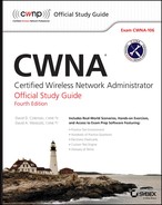
It proposes two new U-NII bands as shown in Figure 6.1. A new 120 MHz wide band called U-NII-2B occupies the frequency space of 5.35 GHZ – 5.47 GHz with six potential 20 MHz channels. Another new 75 MHz wide band called U-NII-4 occupies the 5.85 GHZ – 5.925 GHz frequency space with the potential of four more 20 MHz channels.
Figure 6.1 Proposed U-NII bands
As listed in Table 6.2, the U-NII-2 band would be renamed to U-NII-2A and the U-NII-2 Extended band would be renamed as U-NII-2C. In addition to ten new channels gained from the proposed two new bands, U-NII-2A would gain an extra channel and U-NII-2C would gain an extra channel in frequency space previously used as a guard bands. The FCC is still studying the proposal, but a total of twelve extra 20 MHz channels could become available once approved. Further study of the spectrum sharing and DFS mechanisms may take until late 2014, and we could possibly get approval to use the new spectrum by early 2015.
Table 6.2 The new 5 GHz U-NII bands
| Old Name | New Name | Frequency | Channels |
| U-NII-1 | U-NII-1 | 5.15 − 5.25 GHz | 4 channels |
| U-NII-2 | U-NII-2A | 5.25 − 5.35 GHz | 5 channels |
| U-NII-2B | 5.35 − 5.47 GHz | 6 channels | |
| U-NII-2 Extended | U-NII-2C | 5.47 − 5.725 GHz | 13 channels |
| U-NII-3 | U-NII-3 | 5.725 − 5.85 GHz | 5 channels |
| U-NII-4 | 5.85 − 5.925 GHz | 4 channels |
The good news is that the FCC recognizes the need for more unlicensed spectrum and the word Wi-Fi is mentioned multiple times in NPRM #13-22. The FCC is preparing for the advent of 802.11ac technology that can use 80 MHz and 160 MHz channels and, therefore, more unlicensed spectrum is needed. The FCC has also proposed simplification and standardization of the rules across the entire 5 GHz band. Another reassessment of how to prevent interference with radar satellite transmissions is also part of the proposal. Furthermore, the FCC proposal represents thinking on a global scale, as indicated by the following quote from the proposal: “We are particularly interested in gathering information on ongoing industry standards activity and international efforts to harmonize uses of the 5 GHz band to make more efficient use of the 5 GHz spectrum.”
The National Telecommunication and Information Agency (NTIA) is a US government agency that advises the United States President on spectrum policy and they have also made recommendations based on the FCC proposal. The NTIA document is available at
The growth and future of Wi-Fi in the years ahead will be significantly affected by the proposed FCC rules when they are implemented.
3.6 GHz Band
In 2008, the 802.11y amendment was ratified. This amendment specified the use of the frequency range of 3.65 GHz to 3.7 GHz. This was approved as a licensed band for use in the United States. Unlike other licensed frequencies, the use of this frequency range was nonexclusive and included limitations when used near certain satellite earth stations. Although the project was designed for use in the United States, it was carefully designed to be able to operate in other countries without the need to ratify a new amendment (a process that can take several years to complete). It was designed to operate in any 5 MHz, 10 MHz, or 20 MHz channel. Regulators can make any frequency range available for use.
4.9 GHz Band
The 802.11-2012 standard defines the frequency range of 4.94 GHz to 4.99 GHz in the United States for public safety organizations to use for the protection of life, health, or property. This band is actually a licensed band and is reserved strictly for public safety. This frequency range has also been approved in other countries, such as Canada and Mexico.
In 2004, the 802.11j amendment was ratified, providing support for the 4.9 GHz to 5.091 GHz frequency range for use in Japan. This amendment was later incorporated in the 802.11-2012 standard.
Because of the proximity of these frequencies to the U-NII-1 band, we are seeing more wireless radios providing support for this band.
Future Wi-Fi Frequencies
The 2.4 GHz ISM band has remained the dominant license-free range of frequencies, known as a frequency band, that has been used for Wi-Fi communications since 1997. Although 802.11a was ratified in 1999, the use of the 5 GHz U-NII bands really did not start to catch on until about 2006. Wi-Fi use in the 5 GHz frequency bands continues to expand for a number of reasons: the 2.4 GHz band remains overcrowded, the 5 GHz bands are wider and have more channels, and the advent of 802.11ac will require more frequency space. As mentioned earlier, the FCC has already proposed 195 MHz more frequency space to be made available in two new 5 GHz U-NII bands. In the meantime, the IEEE continues to look toward other spectrum space for future Wi-Fi communications.
60 GHz
As mentioned in Chapter 5, the 802.11ad ratified amendment defines Very High Throughput (VHT) technology that will operate in the unlicensed 60 GHz frequency band. New PHY and MAC layer enhancements have the potential of accomplishing speeds of up to 7 Gbps. Since these ultrahigh frequencies have difficulty penetrating through walls, the technology will most likely be used to provide bandwidth-intensive and short distance communications indoors, such as high definition (HD) video streaming. The technology will not be backward compatible with other 802.11 technology. In September of 2012, the Wi-Fi Alliance designated the WiGig certification to test interoperability of products that operate in the 60 GHz band. The WiGig certification brand was designated with the new logo shown in Figure 6.2.
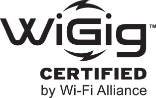
Figure 6.2 WiGig certification logo
Tri-band radios, such as the one in Figure 6.3, will have the capability to provide Wi-Fi access on 2.4 GHz, 5 GHz, and 60 GHz. This tri-band capability should provide for seamless handoff between devices in the short coverage area of the 60 GHz band and the greater coverage area of either the 2.4 GHz or 5 GHz band.
Figure 6.3 2.4 GHz, 5 GHz, and 60 GHz tri-band radio card
White-Fi
As mentioned in Chapter 5, White-Fi is a term used to describe the use of Wi-Fi technology in the unused television RF spectrum also known as TV white space. The 802.11af draft amendment proposes Wi-Fi operations within these unused frequency ranges. If this technology becomes a reality, one of the immediate gains will be greater range because the white space frequencies are below 1 GHz.
Narrowband and Spread Spectrum
There are two primary radio frequency (RF) transmission methods: narrowband and spread spectrum. A narrowband transmission uses very little bandwidth to transmit the data that it is carrying, whereas a spread spectrum transmission uses more bandwidth than is necessary to carry its data. Spread spectrum technology takes the data that is to be transmitted and spreads it across the frequencies that it is using. For example, a narrowband radio might transmit data on 2 MHz of frequency space at 80 watts, while a spread spectrum radio might transmit data over a 22 MHz frequency space at 100 milliwatts.
Figure 6.4 shows a rudimentary comparison of how a narrowband and spread spectrum signal relate to each other. Because narrowband signals take up a single or very narrow band of frequencies, intentional jamming or unintentional interference of this frequency range is likely to cause disruption in the signal. Because spread spectrum uses a wider range of frequency space, it is typically less susceptible to intentional jamming or unintentional interference from outside sources, unless the interfering signal was also spread across the range of frequencies used by the spread spectrum communications.
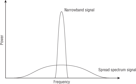
Figure 6.4 Overlay of narrowband and spread spectrum frequency use
Narrowband signals are typically transmitted using much higher power than spread spectrum signals. Typically, the FCC or other local regulatory bodies require that narrowband transmitters be licensed to minimize the risk of two narrowband transmitters interfering with each other. AM and FM radio stations are examples of narrowband transmitters that are licensed to make sure that two stations in the same or nearby market are not transmitting on the same frequency.
Spread spectrum signals are transmitted using very low power levels.
Multipath Interference
One of the problems that can occur with RF communications is multipath interference. Multipath occurs when a reflected signal arrives at the receiving antenna after the primary signal. Figure 6.5 illustrates a signal traveling from the client to the AP. In this illustration, you can see three different signals, each traveling a different path of different distance and duration. This is similar to the way an echo is heard after the original sound.
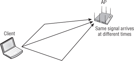
Figure 6.5 Multipath diagram
To illustrate multipath further, let us use an example of yelling to a friend across a canyon. Let's assume you are going to yell, “Hello, how are you?” to your friend. To make sure that your friend understands your message, you might pace your message and yell each word 1 second after the previous word. If your friend heard the echo (multipath reflection of your voice) a half-second after the main sound arrived, your friend would hear “HELLO hello HOW how ARE are YOU you” (echoes are represented by lowercase). Your friend would be able to interpret the message because the echo arrived between the main signals, or the sound of your voice. However, if the echo arrived 1 second after the main sound, the echo for the word hello would arrive at the same time the word HOW arrives. With both sounds arriving at the same time, it may not be possible to understand the message.
RF data communications behave the same way as the sound example. At the receiver, the delay between the main signal and the reflected signal is known as the delay spread. A typical delay spread in an indoor environment can vary from 30 to 270 nanoseconds (ns). If the delay spread is too great, data from the reflected signal may interfere with the same data stream from the main signal; this is referred to as intersymbol interference (ISI). Spread spectrum systems are not as susceptible to ISI because they spread their signals across a range of frequencies. These various frequencies produce different delays in multipath, such that some wavelengths may be affected by ISI whereas others may not. Because of this behavior, spread spectrum signals are typically more tolerant of multipath interference than narrowband signals.
802.11 (DSSS), 802.11b (HR-DSSS), and 802.11g (ERP) are tolerant of delay spread only to a certain extent. 802.11 (DSSS) and 802.11b (HR-DSSS) can tolerate delay spread of up to 500 nanoseconds. Even though the delay spread can be tolerated, performance is much better when the delay spread is lower. The 802.11b transmitter will drop to a lower data rate when the delay spread increases. Longer symbols are used when transmitting at the lower data rates. When longer symbols are used, longer delays can occur before ISI occurs. According to some of the 802.11b vendors, 65 nanoseconds or lower delay spread is required for 802.11b at 11 Mbps.
Because of OFDM's greater tolerance of delay spread, an 802.11g transmitter can maintain 54 Mbps with a delay spread of up to about 150 nanoseconds. This depends on the 802.11g chipset that is being used in the transmitter and receiver. Some chipsets are not as tolerant and switch to a lower data rate at a lower delay spread value.
Prior to 802.11n and 802.11ac MIMO technology, multipath had always been a concern. It was a condition that could drastically affect the performance and throughput of the wireless LAN. With the introduction of MIMO, multipath is actually a condition that can now enhance and increase the performance of the wireless LAN. The enhanced digital signal processing techniques of 802.11n and 802.11ac take advantage of multiple simultaneous transmissions and can actually benefit from the effects of multipath. You will learn more about 802.11n and MIMO in Chapter 18, “High Throughput (HT) and 802.11n.”
Frequency Hopping Spread Spectrum
Frequency hopping spread spectrum (FHSS) was used in the original 802.11 standard and provided 1 and 2 Mbps RF communications using the 2.4 GHz ISM band for legacy radios. The majority of legacy FHSS radios were manufactured between 1997 and 1999. The IEEE specified that in North America, 802.11 FHSS would use 79 MHz of frequencies, from 2.402 GHz to 2.480 GHz.
Generally, the way FHSS works is that it transmits data by using a small frequency carrier space, then hops to another small frequency carrier space and transmits data, then to another frequency, and so on, as illustrated in Figure 6.6. More specifically, FHSS transmits data by using a specific frequency for a set period of time, known as the dwell time. When the dwell time expires, the system changes to another frequency and begins to transmit on that frequency for the duration of the dwell time. Each time the dwell time is reached, the system changes to another frequency and continues to transmit.
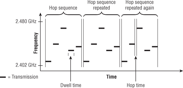
Figure 6.6 FHSS components
Hopping Sequence
FHSS radios use a predefined hopping sequence (also called a hopping pattern or hopping set) comprising a series of small carrier frequencies, or hops. Instead of transmitting on one set channel or finite frequency space, an FHSS radio transmits on a sequence of subchannels called hops. Each time the hop sequence is completed, it is repeated. Figure 6.6 shows a make-believe hopping sequence that consists of five hops.
The original IEEE 802.11 standard mandates that each hop is 1 MHz in size. These individual hops are then arranged in predefined sequences. In North America and most of Europe, the hopping sequences contain at least 75 hops, but no greater than 79 hops. Other countries have different requirements; for example, France uses 35 hops, while Spain and Japan use 23 hops in a sequence. For successful transmissions to occur, all FHSS transmitters and receivers must be synchronized on the same carrier hop at the same time. The 802.11 standard defines hopping sequences that can be configured on an FHSS access point, and the hopping sequence information is delivered to client stations via the beacon management frame.
Dwell Time
Dwell time is a defined amount of time that the FHSS system transmits on a specific frequency before it switches to the next frequency in the hop set. The local regulatory body typically limits the amount of dwell time. For example, the FCC specifies a maximum dwell time of 400 milliseconds (ms) per carrier frequency during any 30-second period of time. Typical dwell times are around 100 ms to 200 ms. The IEEE 802.11 standard specifies that a hopping sequence must consist of at least 75 frequencies, 1 MHz wide. Because the standard specifies a maximum bandwidth of 79 MHz, the maximum number of hops possible for a hop set would be 79. With an FHSS hop sequence consisting of 75 hops and a dwell time of 400 ms, it would take about 30 seconds to complete the hop sequence. After the hop sequence is complete, it is repeated.
Hop Time
Hop time is not a specified period of time but rather a measurement of the amount of time it takes for the transmitter to change from one frequency to another. Hop time is typically a fairly small number, often about 200 to 300 microseconds (μs). With typical dwell times of 100 to 200 milliseconds (ms), hop times of 200 to 300 μs are insignificant. Insignificant or not, the hop time is essentially wasted time, or overhead, and is the same regardless of the dwell time. The longer the dwell time, the less often the transmitter has to waste time hopping to another frequency, resulting in greater throughput. If the dwell time is shorter, the transmitter has to hop more frequently, thus decreasing throughput.
Modulation
FHSS uses Gaussian frequency shift keying (GFSK) to encode the data. Two-level GFSK (2GFSK) uses two frequencies to represent a 0 or a 1 bit. Four-level GFSK (4GFSK) uses four frequencies, with each frequency representing 2 bits (00, 01, 10, or 11). Because it takes transmission cycles before the frequency can be determined, the symbol rate (the rate that the data is sent) is only about 1 or 2 million symbols per second, a fraction of the 2.4 GHz carrier frequency.
Direct Sequence Spread Spectrum
Direct sequence spread spectrum (DSSS) was originally specified in the primary, or root, 802.11 standard and provides 1 and 2 Mbps RF communications using the 2.4 GHz ISM band. An updated implementation of DSSS (HR-DSSS) was also specified in the 802.11b addendum and provides 5.5 and 11 Mbps RF communications using the same 2.4 GHz ISM band. The 802.11b 5.5 and 11 Mbps speeds are known as High-Rate DSSS (HR-DSSS).
802.11b devices are backward compatible with the legacy 802.11 DSSS devices. This means that an 802.11b device can transmit using DSSS at 1 and 2 Mbps and using HR-DSSS at 5.5 and 11 Mbps. However, 802.11b devices are not capable of transmitting using FHSS; therefore, they are not backward compatible with 802.11 FHSS devices.
Unlike FHSS, where the transmitter jumped between frequencies, DSSS is set to one channel. The data that is being transmitted is spread across the range of frequencies that make up the channel. The process of spreading the data across the channel is known as data encoding.
DSSS Data Encoding
In Chapter 2, “Radio Frequency Fundamentals,” you learned about the many ways that RF signals can get altered or corrupted. Because 802.11 uses an unbounded medium with a huge potential for RF interference, it had to be designed to be resilient enough that data corruption could be minimized. To achieve this, each bit of data is encoded and transmitted as multiple bits of data.
The task of adding additional, redundant information to the data is known as processing gain. In this day and age of data compression, it seems strange that we would use a technology that adds data to our transmission, but by doing so, the communication is more resistant to data corruption. The system converts the 1 bit of data into a series of bits that are referred to as chips. To create the chips, a Boolean XOR is performed on the data bit and a fixed-length bit sequence pseudorandom number (PN) code. Using a PN code known as the Barker code, the binary data 1 and 0 are represented by the following chip sequences:
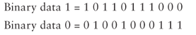
This sequence of chips is then spread across a wider frequency space. Although 1 bit of data might need only 2 MHz of frequency space, the 11 chips will require 22 MHz of frequency carrier space. This process of converting a single data bit into a sequence is often called spreading or chipping. The receiving radio converts, or de-spreads, the chip sequence back into a single data bit. When the data is converted to multiple chips and some of the chips are not received properly, the radio will still be able to interpret the data by looking at the chips that were received properly. When the Barker code is used, as many as 9 of the 11 chips can be corrupted, yet the receiving radio will still be able to interpret the sequence and convert them back into a single data bit. This chipping process also makes the communication less likely to be affected by intersymbol interference because it uses more bandwidth.
The Barker code uses an 11-chip PN; however, the length of the code is irrelevant. To help provide the faster speeds of HR-DSSS, another more complex code, Complementary Code Keying (CCK), is utilized. CCK uses an 8-chip PN, along with using different PNs for different bit sequences. CCK can encode 4 bits of data with 8 chips (5.5 Mbps) and can encode 8 bits of data with 8 chips (11 Mbps). Although it is interesting to learn about, a thorough understanding of CCK is not required for the CWNA exam.
Modulation
After the data has been encoded using a chipping method, the transmitter needs to modulate the signal to create a carrier signal containing the chips. Differential binary phase shift keying (DBPSK) utilizes two phase shifts, one that represents a 0 chip and another that represents a 1 chip. To provide faster throughput, differential quadrature phase shift keying (DQPSK) utilizes four phase shifts, allowing each of the four phase shifts to modulate 2 chips (00, 01, 10, 11) instead of just 1 chip, doubling the speed.
Table 6.3 shows a summary of the data encoding and modulation techniques used by 802.11 and 802.11b.
Table 6.3 DSSS and HR-DSSS encoding and modulation overview
| Data rate (Mbps) | Encoding | Chip length | Bits encoded | Modulation | |
| DSSS | 1 | Barker coding | 11 | 1 | DBPSK |
| DSSS | 2 | Barker coding | 11 | 1 | DQPSK |
| HR-DSSS | 5.5 | CCK coding | 8 | 4 | DQPSK |
| HR-DSSS | 11 | CCK coding | 8 | 8 | DQPSK |
Packet Binary Convolutional Code
Packet Binary Convolutional Code (PBCC) is a modulation technique that supports data rates of 5.5, 11, 22, and 33 Mbps; however, both the transmitter and receiver must support the technology to achieve the higher speeds. PBCC was developed by Alantro Communications, which was purchased by Texas Instruments. PBCC modulation was originally defined as optional under the 802.1b amendment. The introduction of the 802.11g amendment allowed for two additional optional ERP-PBCC modulation modes with payload data rates of 22 and 33 Mbps.
PBCC and ERP-PBCC technology was seen for a short time in the SOHO marketplace. However, the technology was rarely deployed in an enterprise environment.
Orthogonal Frequency Division Multiplexing
Orthogonal Frequency Division Multiplexing (OFDM) is one of the most popular communications technologies, used in both wired and wireless communications. The 802.11-2012 standard specifies the use of OFDM at 5 GHz and also specifies the use of ERP-OFDM at 2.4 GHz. As mentioned in Chapter 5, OFDM and ERP-OFDM are the same technology. OFDM is not a spread spectrum technology, even though it has similar properties to spread spectrum, such as low transmit power and using more bandwidth than is required to transmit data. Because of these similarities, OFDM is often referred to as a spread spectrum technology even though technically that reference is incorrect. OFDM actually transmits across 52 separate, closely and precisely spaced frequencies, often referred to as subcarriers, as illustrated in Figure 6.7.
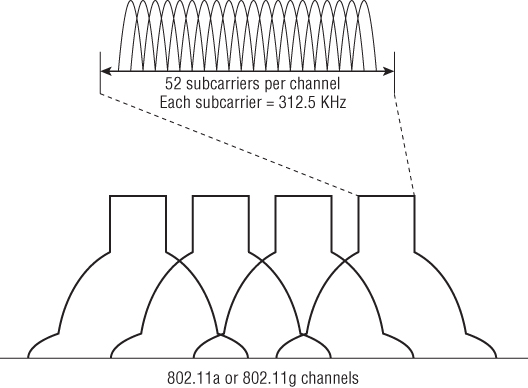
Figure 6.7 802.11 Channels and OFDM subcarriers
The frequency width of each subcarrier is 312.5 KHz. The subcarriers are also transmitted at lower data rates, but because there are so many subcarriers, overall data rates are higher. Also, because of the lower subcarrier data rates, delay spread is a smaller percentage of the symbol period, which means that ISI is less likely to occur. In other words, OFDM technology is more resistant to the negative effects of multipath than DSSS and FHSS spread spectrum technologies. Figure 6.8 represents four of the 52 subcarriers. One of the subcarriers is highlighted so that you can more easily understand the drawing. Notice that the frequency spacing of the subcarriers has been chosen so that the harmonics overlap and provide cancellation of most of the unwanted signals.
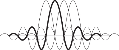
Figure 6.8 Subcarrier signal overlay
The 52 subcarriers are numbered from –26 to +26. Forty-eight of the subcarriers are used to transmit data. The other four, numbers –21, –7, +7, and +21, are known as pilot carriers. These four are used as references for phase and amplitude by the demodulator, allowing the receiver to synchronize itself as it demodulates the data in the other subcarriers.
Convolutional Coding
To make OFDM more resistant to narrowband interference, a form of error correction known as convolutional coding is performed. The 802.11-2012 standard defines the use of convolutional coding as the error-correction method to be used with OFDM technology. It is a forward error correction (FEC) that allows the receiving system to detect and repair corrupted bits.
There are many levels of convolutional coding. Convolutional coding uses a ratio between the bits transmitted vs. the bits encoded to provide these different levels. The lower the ratio, the less resistant the signal is to interference and the greater the data rate will be. Table 6.4 displays a comparison between the technologies used to create the different data rates of both 802.11a and 802.11g. Notice that the data rates are grouped by pairs based on modulation technique and that the difference between the two speeds is caused by the different levels of convolutional coding. A detailed explanation of convolutional coding is extremely complex and far beyond the knowledge needed for the CWNA exam.
Table 6.4 802.11a and 802.11g data rate and modulation comparison
| Data rates (Mbps) | Modulation method | Coded bits per subcarrier | Data bits per OFDM symbol | Coded bits per OFDM symbol | Coding rate (data bits/ coded bits) |
| 6 | BPSK | 1 | 24 | 48 | 1/2 |
| 9 | BPSK | 1 | 36 | 48 | 3/4 |
| 12 | QPSK | 2 | 48 | 96 | 1/2 |
| 18 | QPSK | 2 | 72 | 96 | 3/4 |
| 24 | 16-QAM | 4 | 96 | 192 | 1/2 |
| 36 | 16-QAM | 4 | 144 | 192 | 3/4 |
| 48 | 64-QAM | 6 | 192 | 288 | 2/3 |
| 54 | 64-QAM | 6 | 216 | 288 | 3/4 |
Modulation
OFDM uses binary phase shift keying (BPSK) and quadrature phase shift keying (QPSK) phase modulation for the lower ODFM data rates. The higher OFDM data rates use 16-QAM and 64-QAM modulation. Quadrature amplitude modulation (QAM) is a hybrid of phase and amplitude modulation. The 802.11ac amendment also introduced the use of 256-QAM. A constellation diagram, also known as a constellation map, is a two-dimensional diagram often used to represent QAM modulation. A constellation diagram is divided into four quadrants, and different locations in each quadrant can be used to represent data bits. Areas on the quadrant relative to the horizontal axis can be used to represent various phase shifts. Areas relative to the vertical axis are used to represent amplitude shifts. A 16-QAM constellation diagram uses sixteen different combinations of phase and amplitude shifts, as shown in Figure 6.9. Each of the sixteen different points within the four quadrants can be used to represent four data bits.
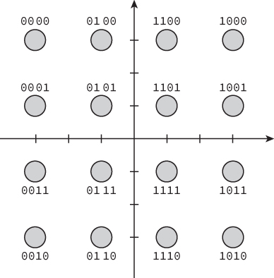
Figure 6.9 16-QAM constellation diagram
2.4 GHz Channels
To better understand how legacy 802.11 (DSSS), 802.11b (HR-DSSS), and 802.11g (ERP) radios are used, it is important to know how the IEEE 802.11-2012 standard divides the 2.4 GHz ISM band into 14 separate channels, as listed in Table 6.5. Although the 2.4 GHz ISM band is divided into 14 channels, the FCC or local regulatory body designates which channels are allowed to be used. Table 6.5 also shows a sample of how channel support can vary.
Table 6.5 2.4 GHz frequency channel plan
| Channel ID | Center frequency (GHz) | US (FCC) | Canada (IC) | Many European countries |
| 1 | 2.412 | X | X | X |
| 2 | 2.417 | X | X | X |
| 3 | 2.422 | X | X | X |
| 4 | 2.427 | X | X | X |
| 5 | 2.432 | X | X | X |
| 6 | 2.437 | X | X | X |
| 7 | 2.442 | X | X | X |
| 8 | 2.447 | X | X | X |
| 9 | 2.452 | X | X | X |
| 10 | 2.457 | X | X | X |
| 11 | 2.462 | X | X | X |
| 12 | 2.467 | X | ||
| 13 | 2.472 | X | ||
| 14 | 2.484 |
Channels are designated by their center frequency. How wide the channel is depends on the technology used by the 802.11 transmitter. When DSSS and HR-DSSS 802.11 radios are transmitting, each channel is 22 MHz wide and is often referenced by the center frequency ± 11 MHz. For example, channel 1 is 2.412 GHz ± 11 MHz, which means that channel 1 spans from 2.401 GHz to 2.423 GHz. It should also be noted that within the 2.4 GHz ISM band, the distance between channel center frequencies is only 5 MHz. Because each channel is 22 MHz wide, and because the separation between center frequencies of each channel is only 5 MHz, the channels will have overlapping frequency space. With the introduction of OFDM in 802.11a, along with its expanded use in 802.11g, 802.11n, and 802.11ac, the frequency width used by an OFDM channel is approximately 20 MHz (as defined by the spectral mask, which you will learn about later in this chapter).
Figure 6.10 shows an overlay of all the channels and how they overlap. Channels 1, 6, and 11 have been highlighted because, as you can see, they are separated from each other by enough frequencies that they do not overlap. In order for two channels to not overlap, they must be separated by at least five channels or 25 MHz. Channels such as 2 and 9 do not overlap, but when 2 and 9 are selected, there is no additional legal channel that can be chosen that does not overlap either 2 or 9. In the United States and Canada, the only three simultaneously nonoverlapping channels are 1, 6, and 11. In regions where channels 1 through 13 are allowed to be used, there are different combinations of three nonoverlapping channels, although channels 1, 6, and 11 are commonly chosen. Enterprise deployments of three or more access points in the 2.4 GHz ISM band normally use channels 1, 6, and 11, which are all considered nonoverlapping.
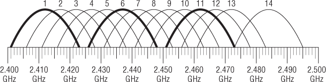
Figure 6.10 2.4 GHz channel overlay diagram
The IEEE 802.11-2012 definitions of nonoverlapping channels in the 2.4 GHz ISM band can be somewhat confusing if not properly explained. Legacy 802.11 (DSSS), 802.11b (HR-DSSS), and 802.11g (ERP) channels all use the same numbering schemes and have the same center frequencies. However, the individual channels' frequency space may overlap. Figure 6.11 shows channels 1, 6, and 11 with 25 MHz of spacing between the center frequencies. These are the most commonly used nonoverlapping channels in North America and most of the world for 802.11b/g/n networks.
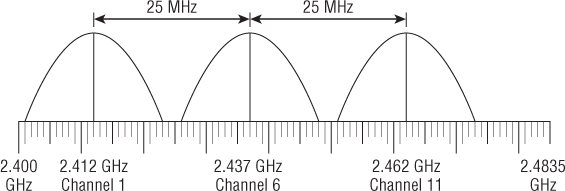
Figure 6.11 HR-DSSS center frequencies
What exactly classifies DSSS or HR-DSSS channels as nonoverlapping? According to the original 802.11 standard, legacy DSSS channels had to have at least 30 MHz of spacing between the center frequencies to be considered nonoverlapping. In a deployment of legacy DSSS equipment using a channel pattern of 1, 6, and 11, the channels were considered overlapping because the center frequencies were only 25 MHz apart. Although DSSS channels 1, 6, and 11 were defined as overlapping, these were still the only three channels used in channel reuse patterns when legacy networks were deployed. This is of little significance anymore because most 2.4 GHz deployments now use 802.11b/g/n technology.
HR-DSSS was introduced under the 802.11b amendment, which states that channels need a minimum of 25 MHz of separation between the center frequencies to be considered nonoverlapping. Therefore, when 802.11b was introduced, channels 1, 6, and 11 were considered nonoverlapping.
The 802.11g amendment, which allows for backward compatibility with 802.11b HR-DSSS, also requires 25 MHz of separation between the center frequencies to be considered nonoverlapping. Under the 802.11g amendment, channels 1, 6, and 11 are also considered nonoverlapping for both ERP-DSSS/CCK and ERP-OFDM.
Although it is very common to represent the RF signal of a particular channel with an arch-type line, this is not a true representation of the signal. As an example, in addition to the main carrier frequency, or main frequency, sideband carrier frequencies are generated, as shown in Figure 6.12. In this example, the IEEE defines a transmit spectrum mask, specifying that the first sideband frequency (–11 MHz to –22 MHz from the center frequency and +11 MHz to +22 MHz from the center frequency) must be at least 30 dB less than the main frequency. The mask also specifies that any additional sideband carrier frequencies (–22 MHz from the center frequency and beyond and +22 MHz from the center frequency and beyond) must be at least 50 dB less than the main frequency.
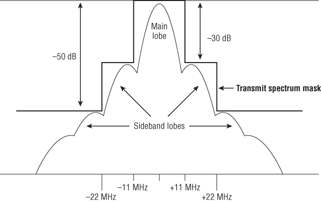
Figure 6.12 IEEE 802.11b transmit spectrum mask
Figure 6.12 illustrates the transmit spectrum mask of an HR-DSSS channel at 2.4 GHz. The transmit spectrum mask is defined to minimize interference between devices on different frequencies. Even though the sideband carrier frequencies are mere whispers of signals compared to the main carrier frequency, even a whisper is noticeable when the person whispering is close to you. This is true for RF devices too.
Figure 6.13 represents 802.11b RF signals on channels 1, 6, and 11. A signal-level line indicates an arbitrary level of reception by the access point on channel 6. At level 1, meaning the AP on channel 6 receives only the signals above the level 1 line, the signals from channel 1 and channel 11 do not intersect (interfere) with the signals on channel 6. However, at the level 2 line, the signals from channel 1 and channel 11 do intersect (interfere) slightly with the signals on channel 6. At the level 3 line, there is significant interference from the signals from channel 1 and channel 11. Because of the potential for this situation, it is important to separate access points (usually 5 to 10 feet is sufficient) so that interference from sideband frequencies does not occur. This separation is important both horizontally and vertically.
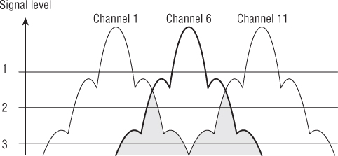
Figure 6.13 Sideband carrier frequency interference
5 GHz Channels
802.11a/n and 802.11ac radios transmit in the 5 GHz U-NII bands: U-NII-1, U-NII-2, U-NII-2 Extended, and U-NII-3. To prevent interference with other possible bands, extra bandwidth is used as a guard. In the U-NII-1 and U-NII-2 bands, the centers of the outermost channels of each band must be 30 MHz from the band's edge. An extra 20 MHz of bandwidth exits in the U-NII-3 band. The unused bandwidth at the edge of each band is known as a guard band. The original three U-NII bands each had four nonoverlapping channels with 20 MHz separation between the center frequencies. A fifth channel was recently added to U-NII-3. The U-NII-2 Extended band has twelve nonoverlapping channels with 20 MHz of separation between the center frequencies. The U-NII-2 Extended band was an eleven channel band for many years, but an extra channel, 144, was added to the band with the advent of 802.11ac. If you want to calculate the center frequency of a channel, multiply the channel by 5 and then add 5000 to the result. (e.g. Channel 36 times 5 equals 180, then add 5000, for a center frequency of 5180 MHz, or 5.18 GHz.)
Figure 6.14 shows the eight U-NII-1 and U-NII-2 channels in the top graphic, the twelve U-NII-2 Extended channels in the center graphic, and the five U-NII-3 channels in the bottom graphic. Channel 36 is highlighted so that it is easier to distinguish a single carrier and its sideband frequencies. The IEEE does not specifically define a channel width; however, the spectral mask of an OFDM channel is approximately 20 MHz.
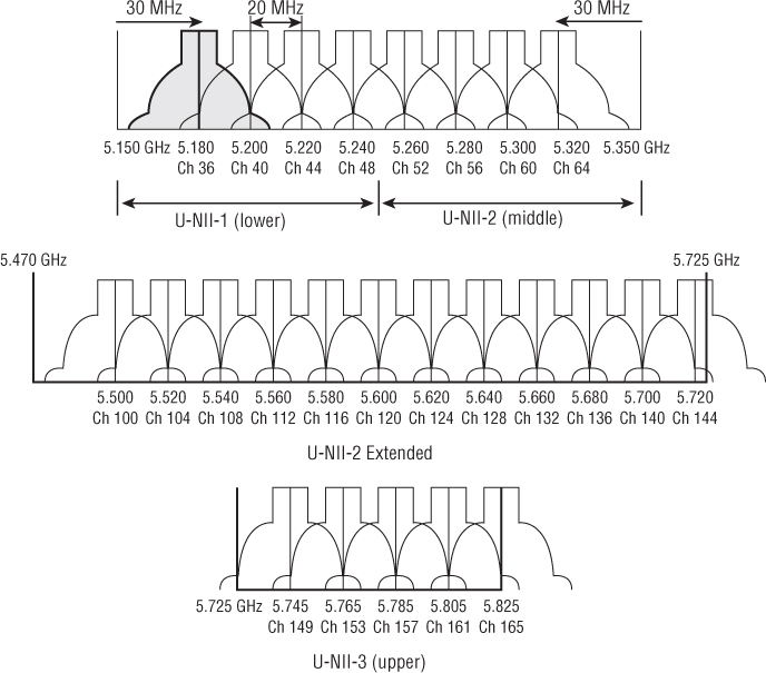
Figure 6.14 U-NII channels
Figure 6.15 depicts a wide overview of all of the 5 GHz channels that can currently be used by 802.11 transmitters. A total of twenty-five 20 MHz channels in the 5 GHz U-NII bands can be used when designing a WLAN with a channel reuse pattern. The channels you can use, of course, depend on the regulations of each country. For example, in most of Europe, the U-NII-3 band is still considered a licensed band, meaning that only twenty channels are available for a channel reuse pattern. In the United States, all the channels were available until 2009. Notice in Figure 6.15 that DFS is required in U-NII-2 and U-NII-2E channels. In these bands, 802.11 radios are required to use dynamic frequency selection (DFS) to avoid interference with radar. In 2009, the Federal Aviation Authority (FAA) reported interference with Terminal Doppler Weather Radar (TDWR) systems. As a result, the FCC suspended certification of 802.11 devices in the U-NII-2 and U-NII-2E bands that required DFS. Eventually, certification was reestablished; however, the rules changed and 802.11 radios were not allowed to transmit in the 5.60 GHz – 5.65 GHz frequency space where TDWR operates. As shown in Figure 6.15, channels 120, 124, and 128 reside in the TDWR frequency space and could not be used for many years in the United States; therefore not all channels were available for a 20 MHz channel reuse. The good news is that as of April 2014, the FCC changed the rules and the TDWR frequency space is once again available. It should also be noted that many enterprise WLAN deployments have completely avoided the use of the DFS channels altogether because many client devices simply have not been certified for any of the DFS channels. A more detailed discussion of 5 GHz Channel reuse patterns and channel planning will be covered in Chapter 12, “WLAN Troubleshooting.”
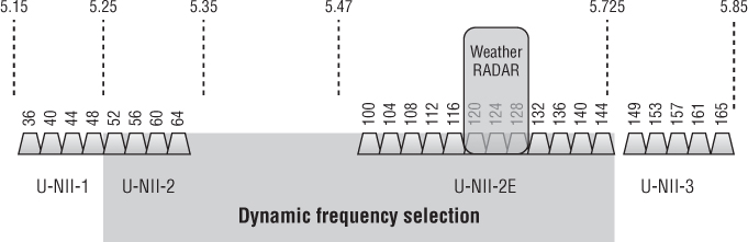
Figure 6.15 U-NII channel overview
802.11n technology introduced the capability of bonding together two 20 MHz channels to create a larger 40 MHz channel. Channel bonding effectively doubles the frequency bandwidth, meaning double the data rates that can be available to 802.11n radios. 40 MHz channels will be discussed in greater detail in Chapter 18, “802.11n.” As shown in Figure 6.16, a total of twelve 40 MHz channels are available to be used in a reuse pattern when deploying an enterprise WLAN. However, in the past, two of the 40 MHz channels have not been used in the United States because they fall within the TDWR band. In Europe, two of the 40 MHz channels cannot be used because they fall within the U-NII-3 band that requires licensing in many countries.
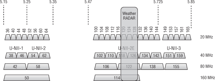
Figure 6.16 U-NII 40 MHz, 80 MHz, and 160 MHz channels
Figure 6.16 also depicts the 80 MHz channels and 160 MHz channels that could possibly be used by 802.11ac radios. In reality, there is not enough frequency space to provide for enough of these channels for proper channel reuse patterns. 802.11ac capabilities, including 80 MHz and 160 MHz channels, are discussed in Chapter 19, ”Very High Throughput (VHT) and 802.11ac.”
As mentioned earlier in this chapter, the FCC has proposed two more U-NII bands with 195 MHz of frequency space for unlicensed use by 802.11 radios. The FCC has also proposed the simplification and standardization of the rules across the entire 5 GHz band. As of April 2014, DFS rules for radar detection and avoidance have changed and the frequency band used for weather radar is now available for Wi-Fi radios. Should all these proposals be implemented and all the 5 GHz spectrum space be made available, there would be as many as thirty-seven 20 MHz channels that could be used by Wi-Fi radios, as depicted in Figure 6.17.
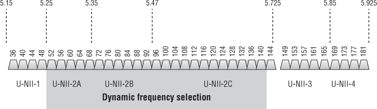
Figure 6.17 Potential U-NII-1 through U-NII-4 20 MHz channels
As 802.11ac technology becomes more commonplace, the need for the extra frequency space is even more important. As shown in Figure 6.18, if all the U-NII-1 through U-NII-4 spectrum is indeed made available, channel reuse patterns using larger channels can become a reality. A total of eighteen 40 MHz channels would be available for 802.11n or 802.11ac radios. A reuse pattern of nine 80-MHz channels could be designed for use by 802.11ac radios. There would even be enough frequency space for four 160 MHz channels that could be used by a second generation of 802.11ac radio chipsets in the near future. Please keep in mind that the proposed extra spectrum is still not currently available and that rules and regulations about frequency use can vary from country to country.
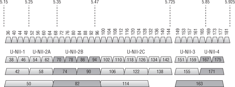
Figure 6.18 Potential 40 MHz, 80 MHz, and 160 MHz channels
As stated earlier, the IEEE does not specifically define a channel width; however, the spectral mask of an OFDM channel is approximately 20 MHz. The spectral mask of 802.11n or 802.11ac bonded channels is obviously much larger.
As seen in Figure 6.19 of the OFDM spectrum mask, the sideband carrier frequencies do not drop off very quickly, and therefore the sideband frequencies of two adjacent valid channels overlap and are more likely to cause interference. The 802.11a amendment, which originally defined the use of OFDM, required only 20 MHz of separation between the center frequencies for channels to be considered nonoverlapping. All 20 MHz channels in the 5 GHz U-NII bands use OFDM and have 20 MHz of separation between the center frequencies. Therefore, all 5 GHz OFDM channels are considered nonoverlapping by the IEEE. In reality, some sideband carrier frequency overlap exists between any two adjacent 5 GHz channels. Luckily, due to the number of channels and the channel spacing, it is easy to separate adjacent channels and prevent interference with a proper channel reuse plan.
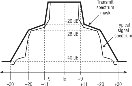
Figure 6.19 OFDM spectrum mask
Adjacent, Nonadjacent, and Overlapping Channels
In the preceding paragraphs, you learned how the IEEE 802.11-2012 standard defines nonoverlapping channels. DSSS (legacy) channels require 30 MHz of separation between the center frequencies to be considered nonoverlapping. HR-DSSS (802.11b) and ERP (802.11g) channels require 25 MHz of separation between the center frequencies to be considered nonoverlapping. And finally, 5 GHz OFDM channels require 20 MHz of separation between the center frequencies to be considered nonoverlapping. Why are these definitions important? When deploying a WLAN, it is important to have overlapping cell coverage for roaming to occur. However, it is just as important for these coverage cells not to have overlapping frequency space. A channel reuse pattern is needed because overlapping frequency space causes degradation in performance. The design aspects of channel reuse patterns are discussed in great detail in Chapter 12, “WLAN Troubleshooting.”
An often debated topic is what defines an adjacent channel. The 802.11-2012 standard loosely defines an adjacent channel as any channel with nonoverlapping frequencies for the DSSS and HR-DSSS PHYs. With ERP and OFDM PHYs, the standard loosely defines an adjacent channel as the first channel with a nonoverlapping frequency space. In other words, the IEEE definition of adjacent channels is almost exactly the same as the definition of nonoverlapping channels that has been discussed earlier. Although not specifically defined, single-channel 2.4 GHz HT (802.11n) devices would follow the 802.11g definitions, and single-channel 5 GHz HT devices would follow the 802.11a definitions. Confused? Table 6.6 illustrates the CWNP program's interpretation of these concepts.
Table 6.6 IEEE adjacent and overlapping channels
| DSSS (802.11) | HR-DSSS (802.11b) | ERP (802.11g) | OFDM (802.11a) | |
| Frequency band | 2.4 GHz ISM | 2.4 GHz ISM | 2.4 GHz ISM | U-NII bands |
| Adjacent | ≥ 30 MHz | ≥ 25 MHz | = 25 MHz | = 20 MHz |
| Overlapping | > 30 MHz | > 25 MHz | > 25 MHz | N/A |
Throughput vs. Bandwidth
Wireless communication is typically performed within a constrained set of frequencies known as a frequency band. This frequency band is the bandwidth. Frequency bandwidth does play a part in the eventual throughput of the data, but many other factors also determine throughput. In addition to frequency bandwidth, data encoding, modulation, medium contention, encryption, and many other factors also play a large part in data throughput.
Care should be taken not to confuse frequency bandwidth with data bandwidth. Data encoding and modulation determine data rates, which are sometimes also referred to as data bandwidth. Simply look at the 5 GHz channels and OFDM as an example. OFDM 802.11a radios can transmit at 6, 9, 12, 18, 24, 36, 48, or 54 Mbps, yet the frequency bandwidth for all the U-NII band channels is the same for all of these speeds. What changes between all of these speeds (data rates) is the modulation and coding technique. The proper term for the changes in speed due to modulation and coding is data rates; however, they are also often referred to as data bandwidth.
One of the surprising facts when explaining wireless networking to a layperson is the actual throughput that an 802.11 wireless network provides. When novices walk through a computer store and see the packages of 802.11 devices, they likely assume that a device that is labeled as 300 Mbps is going to provide throughput of 300 Mbps. A medium access method known as Carrier Sense Multiple Access with Collision Avoidance (CSMA/CA) attempts to ensure that only one radio device can be transmitting on the medium at any given time. Because of the half-duplex nature of the medium and the overhead generated by CSMA/CA, the actual aggregate throughput is typically 50 percent or less of the data rates for 802.11a/b/g legacy transmissions, and 60-70 percent of the data rates for 802.11n/ac transmissions. In addition to the throughput being affected by the half-duplex nature of 802.11 communications, the throughput is affected differently based on the frequency used. HT and OFDM technologies are used in both the 5 GHz and 2.4 GHz bands. Because of the higher level of RF noise that is typical in the 2.4 GHz ISM band, throughput of 2.4 GHz devices will typically be less than the 5 GHz devices.
It is also very important to understand that the 802.11 RF medium is a shared medium, meaning that in any discussion of throughput, it should be thought of as aggregate throughput. For example, if a data rate is 54 Mbps, because of CSMA/CA, the aggregate throughput might be about 20 Mbps. If five client stations were all downloading the same file from an FTP server at the same time, the perceived throughput for each client station would be about 4 Mbps under ideal circumstances. When 802.11n and 802.11ac radios are used, the aggregate throughput is typically 65 percent of the advertised data rate. The medium contention overhead created by CSMA/CA is typically about 35 percent of the bandwidth. Medium contention overhead is 50 percent or more when using legacy 802.11a/b/g radios.
RTS/CTS (which you will learn about in Chapter 9, “802.11 MAC Architecture”) can also affect throughput by adding communication overhead. In some environments, fragmentation and RTS/CTS can actually increase throughput if the initial throughput was low because of communication problems.
Variables at almost all layers of the OSI model can affect the throughput of 802.11 communications. It is important to understand the different causes, their effects, and what, if anything, can be done to minimize their effect on overall data throughput.
Communication Resilience
Many technologies that have been covered in this chapter either directly or indirectly provide resilience to 802.11 communications. Spread spectrum spreads the data across a range of frequencies, making it less likely for a narrowband RF signal to cause interference. FHSS is inherently more resilient to narrowband interference than OFDM, and OFDM is more resilient to narrowband interference than DSSS. Spread spectrum technology uses a range of frequencies, which inherently adds resilience because delay spread and ISI will vary between the different frequencies. Additionally, data encoding provides error recovery methods, helping to reduce the need for retransmission of the data.
Summary
This chapter focused on the technologies that make up wireless networking and spread spectrum. 802.11, 802.11b, 802.11g, and 802.11n radios use the 2.4 GHz ISM band, while 802.11a/n and 802.11ac radios use 5 GHz U-NII bands. 802.11n HT radios can use both the 2.4 GHz ISM band and the 5 GHz U-NII bands. The ISM and U-NII bands discussed in this chapter are as follows:
- ISM 902 – 928 MHz—industrial
- ISM 2.4 – 2.5 GHz—scientific
- ISM 5.725 – 5.875 GHz—medical
- U-NII-1 5.150 – 5.250 GHz—lower
- U-NII-2 5.250 – 5.350 GHz—middle (also known as U-NII-2A in the proposed frequency updates)
- U-NII-2 extended 5.470 – 5.725 GHz—Extended (also known as U-NII-2C in the proposed frequency updates)
- U-NII-3 5.725 – 5.85 GHz—upper
- Proposed U-NII-2B 5.35 – 5.47 GHz
- Proposed U-NII-4 5.85 – 5.925 GHz
In addition to the ISM and U-NII bands, the following bands were discussed:
- 4.94–4.99 GHz—US public safety
- 4.9–5.091 GHz—Japan
- 60 GHz
- < 1 GHz—White-Fi
Spread spectrum technology was introduced and described in detail along with OFDM and convolutional coding. The following are key spread spectrum technologies and terms that we discussed:
- FHSS
- Dwell time
- Hop time
- DSSS
This chapter ended with a comparison of throughput and bandwidth and a review of the communication resilience of the technologies used in 802.11.
Exam Essentials
- Know the technical specifications of all the ISM and U-NII bands. Make sure that you know all of the frequencies, bandwidth uses, and channels. Be sure to understand the potential effects of the proposed extra 195 MHz of frequency space and what it means for available channels in 5 GHz.
- Know spread spectrum. Spread spectrum can be complicated and has different flavors. Understand FHSS, DSSS, and OFDM (although OFDM is not a spread spectrum technology, it has similar properties and you have to know it). Understand how coding and modulation work with spread spectrum and OFDM.
- Understand the similarities and differences between the transmission methods discussed in this chapter. There are differences and similarities between many of the topics in this chapter. Carefully compare and understand them. Minor subtleties can be difficult to recognize when you are taking the test.
Review Questions
- Which of the following are valid ISM bands? (Choose all that apply.)
- 902 MHz – 928 MHz
- 2.4 GHz – 2.5 GHz
- 5.725 GHz – 5.85 GHz
- 5.725 GHz – 5.875 GHz
- Which of the following are valid U-NII bands? (Choose all that apply.)
- 5.150 GHz – 5.250 GHz
- 5.470 GHz – 5.725 GHz
- 5.725 GHz – 5.85 GHz
- 5.725 GHz – 5.875 GHz
- Which technologies are used in the 2.4 GHz ISM band? (Choose all that apply.)
- FHSS
- ERP
- DSSS
- HR-DSSS
- 802.11n (HT radios) can transmit in which frequency bands? (Choose all that apply.)
- 2.4 GHz – 2.4835 GHz
- 5.47 GHz – 5.725 GHz
- 902 GHz – 928 GHz
- 5.15 GHz – 5.25 GHz
- In the U-NII-1 band, what is the center frequency of channel 40?
- 5.2 GHz
- 5.4 GHz
- 5.8 GHz
- 5.140 GHz
- What is the channel and band of a Wi-Fi transmission whose center frequency is 5.300 GHz?
- U-NII-1 channel 30
- U-NII-1 channel 60
- U-NII-2 channel 30
- U-NII-2 channel 60
- The 802.11-2012 standard requires how much separation between center frequencies for HR-DSSS channels to be considered nonoverlapping?
- 22 MHz
- 25 MHz
- 30 MHz
- 35 MHz
- 40 MHz
- What best describes hop time?
- The period of time that the transmitter waits before hopping to the next frequency
- The period of time that the standard requires when hopping between frequencies
- The period of time that the transmitter takes to hop to the next frequency
- The period of time the transmitter takes to hop through all of the FHSS frequencies
- As defined by the IEEE-2012 standard, how much separation is needed between center frequencies of channels in the U-NII-2 Extended band?
- 10 MHz
- 20 MHz
- 22 MHz
- 25 MHz
- 30 MHz
- When deploying an 802.11g (ERP-OFDM) wireless network with only two access points, which of these channel groupings would be considered nonoverlapping? (Choose all that apply.)
- Channels 1 and 3
- Channels 7 and 10
- Channels 3 and 8
- Channels 5 and 11
- Channels 6 and 10
- Which spread spectrum technology specifies data rates of 22 Mbps and 33 Mbps?
- DSSS
- ERP-PBCC
- OFDM
- PPtP
- If data is corrupted by previous data from a reflected signal, this is known as what?
- Delay spread
- ISI
- Forward error creation
- Bit crossover
- Assuming all channels are supported by a 5 GHz access point, how many possible 20 MHz channels can be configured on the access point?
- 4
- 11
- 12
- 25
- Which of these technologies is the most resilient against the negative effects of multipath?
- FHSS
- DSSS
- HR-DSSS
- OFDM
- HR-DSSS calls for data rates of 5.5 Mbps, and 11 Mbps. What is the average amount of aggregate throughput percentage at any data rate when legacy 802.11a/b/g radios are transmitting?
- 80 percent
- 75 percent
- 50 percent
- 100 percent
- What are the names of the two additional U-NII bands proposed by the FCC that provide for 195 MHz of additional spectrum at 5 GHz? (Choose all that apply.)
- U-NII-1
- U-NII-2A
- U-NII-2B
- U-NII-2C
- U-NII-3
- U-NII-4
- In the United States, 802.11 radios were not allowed to transmit on which range of frequencies to avoid interference with Terminal Doppler Weather Radar (TDWR) systems?
- 5.15 GHz – 5.25 GHz
- 5.25 GHz – 5.25 GHz
- 5.60 GHz – 5.65 GHz
- 5.85 GHz – 5.925 GHz
- What are the modulation types used by OFDM technology? (Choose all that apply.)
- QAM
- Phase
- Frequency
- Hopping
- The Barker code converts a bit of data into a series of bits that are referred to as what?
- Chipset
- Chips
- Convolutional code
- Complementary code
- A 20 MHz OFDM channel uses how many 312.5 KHz data subcarriers when transmitting?
- 54
- 52
- 48
- 36