This chapter covers the minimum requirements for installation, testing, and commissioning of cathodic protection systems (impressed current and galvanic) for buried and immersed steel structures, such as buried pipelines, distribution networks, in-plant facilities, and marine structures, which includes installation, startup, measurements, testing, commissioning, and inspection procedures.
This chapter is generally applicable to buried structures. For specific structural systems (installations that require special attention, techniques, and materials are not covered. Each such installation requires special considerations based on many influencing factors and cannot be covered adequately in a single standard), this chapter could also be used in conjunction with the project specification and drawings for those structures.
This chapter covers the minimum requirements for installation, testing, and commissioning of cathodic protection (CP) systems (impressed current and galvanic) for buried and immersed steel structures such as buried pipelines, distribution networks, in-plant facilities, and marine structures, which includes installation, startup, measurements, testing, commissioning, and inspection procedures.
This chapter is generally applicable to buried structures. For specific structural systems (Installations that require special attention, techniques, and materials are not covered. Each such installation requires special considerations based on many influencing factors and cannot be covered adequately in a single standard), this chapter could also be used in conjunction with the project specification and drawings for those structures.
Because of the inaccessible nature of much of the CP equipment in service, it is necessary to confirm, prior to shipment to site and prior to installation, that materials and equipment comply with the appropriate standard specification to avoid unnecessary and protracted delays while replacements are sought or repairs are undertaken.
7.1. Galvanic Anodes
Anodes should be inspected for the following:
1. Freedom from electrical damage.
2. Electrical security and continuity of connections.
3. Anode-to-core continuity.
4. Correct metal mass.
5. Correct profile.
6. Compliance of anodes (including anode backfill) with “standards.”
Insulation of all cable tails should be inspected for the presence of nicks, cuts, or other forms of damage.
Packaged anodes should be inspected and steps taken to ensure that backfill material completely surrounds the anode. The individual container for the backfill material and anode should be intact. If individually packaged anodes are supplied in waterproof containers, that container must be removed before installation. Packaged anodes should be kept dry during storage. Electrical continuity between anode and lead wire should be tested without compromising the integrity of the package.
Other galvanic anodes, such as unpackaged “Bracelet” type or ribbon, should be inspected to ensure that dimensions conform to design specifications and that any damage during handling does not affect application. If a coating is used on bands and the inner side of “Bracelet” anode segments, it should be inspected and, if damaged, repaired before the anodes are installed.
When a separate suspension such as rope is used to support the weight of an anode, the suspension system should be inspected for damage, and all defects should be repaired.
In the case of weld-on type of galvanic anodes, steel cores should be inspected for conformance to specifications. If anode cores have welded joints or connections, these should be inspected to ensure compliance with structure-welding specifications.
When galvanic anode suspension cables are used for the lead wire, the cables should be inspected for strength and good electrical contact with the anode. Where separate suspension cables are used, care should be taken to ensure that anode lead wires are not in such tension so as to damage the lead wires or connections.
If coatings are specified for galvanic anode supports or suspension cables, they should be visually inspected and the coatings repaired if damaged.
7.2. Impressed Current Anodes
Impressed current anodes should be inspected for conformance to standard specifications concerning correct anode material and size, length of lead wire, and secure cap, if used. Care should be taken to avoid cracking or damaging anodes during handling and installation.
Lead wire should be carefully inspected to detect defects in insulation. Care should be taken to avoid damage to insulation on wires. Defects in the lead wire must be repaired, or the anode must be rejected. Anode backfill material should conform to standard specifications. Cables should be inspected to ensure that cable runs can be achieved, preferably in one take-off from a reel or drum and that the cable is of correct construction for the intended application. Insulation of all cables should be inspected for the presence of nicks, cuts, cracks, abrasions, and excessive thinning below a specified thickness or other forms of damage.
7.3. Transformer/Rectifier Equipment
Testing should be carried out before acceptance of a transformer/rectifier unit, to confirm compliance with the standard specifications and to ensure that the equipment is suitable for the intended purpose.
The following tests should be carried out on transformer/rectifier equipment:
1. Visual inspection to ensure that all rectifier and surge protection equipment and all specified current outputs have been provided.
2. Polarity check to ensure that output terminals are correctly identified.
3. A step-by-step check of the unit output against the calculated load, to ensure that a uniform control pattern is available.
4. Insulation resistance tests conducted and recorded on all transformer/rectifier(s) in accordance with company-approved testing method to ensure that the equipment has neither deteriorated nor has been damaged during shipment.
5. The contractor to ensure that Oil-cooled transformer/rectifier(s) be filled to the normal liquid level before being placed in operation. Five samples of insulation oil should be tested for dielectric strength and have the results and the average recorded if required by the Company.
6. Functional tests of time switches to be installed.
7. Functional tests of other special equipment to be fitted.
Where appropriate, each insulating joint should be electrically tested, pressure tested, and finally electrically retested. Where supplied for welding into position, the associated pipe pieces should be of a sufficient length to prevent damage to the joint insulation by heat transfer during the welding process. During welding, the manufacturer's recommendations on cooling rate should be followed.
7.4. Excavation and Backfilling
All necessary excavating, shoring, sheathing, bracing, pumping, and backfilling required to install ground beds, cables and connections as specified need to be provided. When excavation is carried below grade, the fill-to-grade material should be well tamped. In no case should any frozen earth be used for backfilling, nor should any backfilling be placed on or against frozen earth. Trenches under roads and paved areas should be backfilled with coarse sand to meet the approval of the Company. Excavated material should not be used.
Any earth excavating procedure presents safety hazards related to the presence of unstable soils, water, released products, and moving equipment. Personnel involved in excavation, equipment installation, and backfilling should be knowledgeable about and should follow the safety standards.
The excavation should provide adequate space for the installation of anodes, cables, and ancillary equipment. Special attention should be given to sloping or shoring the sides of the excavation to make them stable. Metallic pipelines should be located through the use of a line locator and mechanical probe. Excavations within 600mm of the pipe should be done by hand. Nonmetallic lines in the immediate proximity of excavations should be exposed by hand. Damage to pipelines, coatings, conduit, cable, or other buried equipment as a result of excavation should be repaired in accordance with standards at a cost to the contractor before backfilling.
All electrical and control equipment marred by shipment or erection should be touched up, using the same color and type of finish as the original, according to the standard for painting. The transformer/rectifier cabinet must not be coated with mastics, tars, or any other similar materials.
7.5. Installation of CP Systems for Buried Pipelines
This section specifies the minimum requirements for the installation of CP systems that will control corrosion of the buried pipelines.
7.5.1. Installation of Impressed Current Systems
• Ground beds
Because anodes are often brittle, care should be taken to ensure that they are not damaged by handling. Unless specially designed, they should not be suspended or lowered by their cable tails because connections are essentially electrical and not mechanical. Proper implements, tools, and facilities should be provided and used for the safe and convenient performance of the work.
All materials should be examined carefully for damage and other defects immediately before installation. Defective materials should be marked and held for inspection by the Company, so that they may prescribe corrective repairs or reject the materials.
Anodes should be installed in the center of any backfill, and the backfill should be gently tamped into place around the anode. Care should be taken to prevent anode breakage.
On completion of the installation of a ground bed, the resistance of the ground bed to the remote earth should preferably be measured by using an alternating current (AC) earth tester. Measured resistance should be compared with the design resistance.
Resistance in a ground bed may be lowered by permanently adding water to each anode by using plastic water piping and drip-irrigation fittings. However, where ground bed resistance is still too high, the ground bed will need to be extended.
The ground beds should be of the following forms as will be specified by the design documents.
• Horizontal ground bed
Horizontal ground beds should be constructed in locations as determined in the design drawings and with the following considerations:
• Anodes should be installed horizontally in a group and connected in parallel in the trench at a minimum depth of 2000- and at 4500-mm centers, unless otherwise specified by the design documents.
• A bedding of the trench should be made 600mm wide and with a depth and length as specified on the design drawings. The trench walls should be vertical throughout, and the bedding should be tamped to provide a uniform surface.
• Anodes should be installed with a minimum of 150-mm compacted metallurgical grade coke breeze encapsulating the circumference and a minimum of 2250-mm coke breeze extending beyond each end. The anode lead wires should then be brought out of the coke breeze and spliced, taped, and coated to the positive header cable.
• The coke breeze should be thoroughly and properly tamped; for maximum coupling between the anode and the earth. Care should be taken during backfilling to avoid damage to the anode. Loose backfill can give disappointingly high resistances and shorten the anode life.
• The process of tamping down should be achieved in stages after every 10-cm layer of coke breeze has been poured into the trench. The tamping down process while having to be very thorough should in no way damage the anodes.
The ground bed excavation should then be backfilled with fine soil by hand until a minimum cover of 200mm over coke breeze is achieved. Power equipment should then be used to restore the excavation to the original ground level.
Before backfilling the trench, vent pipes should be placed at their predetermined locations on each anode and filled with gravel. If the backfilling operation does not produce sufficient compaction to eliminate the possibility of future settling, a berm should be installed over the backfill such that original elevations will be met.
• The header cable should then be laid on a 100-mm layer of fine sand covered with a further 100mm of sand. The remaining space of the trench should be backfilled with earth to the ground level. For the protection of the cable, protective tiles or bricks should then be installed on top of the sand as shown in the standard drawing. The remaining space of the cable trench should be filled with backfill.
The following are to be noted:
1. In horizontal installations, ditch width at anode depth should be that of the design width of the carbonaceous backfill layer. Where this is not possible because of trenching conditions, form boards may be used to restrict the backfill. After the carbonaceous material and anodes have been placed inside the form boards and tamped earth outside, the form boards must be withdrawn. The coke breeze should be retamped to fill the space occupied by the form boards.
2. Top soil should be stripped and stockpiled at the commencement of excavation and redistributed over the excavated area upon completion.
3. Maximum anode loading should be determined by employing good engineering practices.
4. Due consideration to the use of anode irrigation equipment should be given by the contractor. Where applicable, complete details of the proposed equipment and installation methods should be provided for approval of the relevant experts.
• Vertical ground bed
Vertical ground beds should be constructed in locations as determined in design drawings and with the following considerations:
• Anodes should be installed vertically in a group (at straight line) in separate holes and connected in parallel.
• The anode hole should be made so that it is at least 1300mm (4ft) deeper than the length of the anode rod and 200mm (8in) larger in diameter than the diameter of the anode.
• The bottom of the hole should be filled to a depth of 300mm (1ft) of metallurgical grade coke breeze, and tamped until well packed. Tamping will reduce the anode-to-soil resistance, and will thereby increase the efficiency of the installation. The anode must be centered carefully in hole, and the backfill material should be poured into the hole to cover the anode. The backfill should be gently tamped into place around the anode. When tamping with power tampers (preferred) or by hand, particular care must be taken to prevent damage to the anode or to the anode lead wire.
• This procedure should be repeated until the anode is covered by at least 300mm (1ft) of backfill. After making the electrical connection of the anode lead wire-to-header cable the vent pipe should be placed in its predetermined location and filled with gravel.
The following should be noted:
The purpose of the gravel is to provide a gas vent for the oxygen, chlorine and, in some special cases, hydrogen, which may evolve under various conditions from the anode area.
• The hole should then be backfilled with the excavated earth to the ground level. The header cable should be laid on a 100-mm layer of fine sand covered with a further 100mm of sand. For the protection of the cable, protective tiles or bricks should be installed on top of the sand as shown in the standard drawing. The remaining space of the cable trench should be filled with backfill.
• Deep-well ground bed
Deep-well ground beds should be constructed in locations as determined in the design drawings, and with the following considerations:
– The anode bed for a deep-well ground bed should be drilled with a rotary rig (using mud or air) or by cable tools where applicable.
– Depending on the type of the drilling rig used, the following possibility may be considered: the use of the rig itself for placing the anode system in the hole where a well is being drilled in soft formations that cannot be depended on to hold an open hole without collapsing; a rotary rig can continue circulating drilling mud in the hole, after reaching the design depth, until just prior to placing the anode system.
– All drilling procedure and installation of casing and well head completions should be in accordance with public laws.
– Casing should be set prior to installation of anodes to prevent damage to the lead wires.
– Downhole components should not be bundled or fastened with materials that will cause gas entrapment or backfill bridging.
– The lead wire-to-anode connection resistance should be checked before installation.
– The lead wire insulation must be protected from abrasion and sharp objects. Prior to installation, lead wire insulation should be visually inspected for flaws or damage.
– Further assurance of lead wire insulation integrity may be achieved by conducting suitable wet tests using proper safety precautions.
– When installing a suspended anode, where separate suspension is required, care should be taken to ensure that the lead wire is not in sufficient tension to damage the anode lead wire or connections.
– The deep well should be either of the dry (closed hole) or the wet (open hole) type as specified by design documents.
The following are to be noted:
1. When possible, ground beds should be located at a minimum distance of 30m from any buried metal structures.
2. Salt should be added to deep-well ground beds for the purpose of lowering the resistance of the ground bed is absolutely forbidden.
• Closed well (closed hole)
• Individual anodes should be centered in the well with a suitable device that will allow passage of backfill material, will not entrap gases, and will not damage lead wire insulation or preclude proper placement of anodes.
• Before pumping backfill material, all anodes should be placed at the predetermined depth and the vent pipe should be set from the bottom anode to the top of the well.
• The following should be considered: Before pouring or shoveling backfill material from the top of the well, displace the drilling mud with clear water, and place the vent pipe and two deepest anodes at their predetermined depth. Pour backfill material into the well to cover the first anode, place the third anode, and repeat the procedure for each following anode.
• The backfill material should be wetted, as may be required to prevent bridging the well.
• The following should be considered: If strata resistivities permit moderate vertical shifting of anode position, the release of anode lead wire tension to provide slack may prevent excessive loading of the lead wire or the lead wire-to-anode connection in the event of caving or settling of the backfill material.
• Type 3 coke breeze should be used as a backfill unless specified otherwise by experts.
• All deep ground bed installations (rectifier, well, and venting location) should be marked with adequate signs so as to advise all personnel to vent the installation properly before commencing work and to keep fire away.
• One plastic vent pipe should be used to aid in dissipating gases to the atmosphere.
• The following criterion should be kept in mind: The plastic vent pipe that extends below the anodes normally has a series of small holes on 15- to 30-cm centers drilled in the immediate vicinity of the anodes. These holes should be of such a small diameter as to prevent the entry of the backfill material into the vent pipe.
• The vent pipe should be capped at both ends during the backfilling operation to minimize filling with backfill material or mud.
• The following should be considered: A threaded fitting installed at the surface end of the vent pipe will facilitate water or air injections that may be required to eliminate gas blockage. The use of a screened bushing on the threaded fitting will prevent the entry of insects and foreign objects. The connection of a hose to the vent pipe with the end inserted in an open water container will provide a visible test of gas venting.
• Vent pipes should be located so as to preclude the entry of corrosive gases into the test box and rectifier. All lead wire conduits should be sealed.
• A uniformly low resistivity backfill should be installed in the well until the top anode is adequately covered. Suitable backfill will decrease the anode resistance to the electrolyte, increase anode life, prevent caving, and facilitate gas venting. The remainder of the well should be filled with a nonconductive, nonabrasive permeable backfill material (sand or pea gravel).
• Backfilling may be accomplished by pumping, shoveling, or pouring. Backfilling method usually is determined by the characteristics of the strata and the backfill material used.
• The backfill material should be presoaked with water as is recommended to minimize the possibility of bridging. A wetting agent may be used.
• Backfilling of wells containing drilling mud and/or water may be accomplished by pumping the backfill material (in slurry form) to the bottom of the well and allowing the well to fill from the bottom up to displace the drilling mud and/or water.
• Observations of the change in anode resistance to the earth should be used to determine if the backfill material has been placed around the anode.
• Open well (open hole)
• Each anode should be suspended, placed in position, raised, lowered, or removed for inspection by individual polypropylene ropes.
• Anodes should be centered in the casing, considering the required spacing between them, within the aqueous electrolyte.
• The final depth of the well will depend on the subsurface strata and the number and length of the anodes. The approximate depth should be defined by the designer. Necessary precautions should be taken to prevent deleterious modification of ground water quality.
• Each anode should be provided with an individual insulated lead wire, or a cable sufficiently long should be connected to the anode lead wire with a cable connector (line tap) and in-line (two-way) splicing kit.
• Each cable group of each deep well should be brought inside the positive test box (type 2) located at the deep-well head.
• The test box should be installed as per the standard requirement for individual termination of anodes and rectifier positive lead wires.
• A shunt should be installed in each anode circuit to monitor the current output.
• Resistors should be installed in individual anode circuits to balance anode outputs.
• Anode wires should be sealed to prevent capillary action between insulation layers, as may be necessary to prevent corrosive elements from entering the test box.
• Lead wire entry should be sealed as may be necessary to prevent the entry of gases.
7.5.2. Installation of Transformer/Rectifier Equipment
It is essential that transformer/rectifier units be installed by suitably qualified personnel and be installed in accordance with the requirements of the National Electrical Code NFPA-70, Latest Edition and this Standard.
The manufacturer's installation and operating manuals should be available at the site before installation of the transformer/rectifier. The instructions contained therein should be adhered to.
Air-cooled transformer/rectifier(s) should be installed pole mounted by means of using four roll and plug-type connectors and in a free place for cooling purposes.
Oil-cooled transformer/rectifier(s) should be installed in nonhazardous areas and away from any equipment that creates heat. Oil-cooled transformer/rectifier(s) should be installed on a concrete plinth in accordance with the details specified by standards as required by the job.
Transformer/rectifiers should not be installed in series or in parallel in the same CP circuit. Transformer/rectifiers should be installed in nonhazardous area. If this is not possible, the construction of the rectifier units should fulfill the requirements of the hazardous area classification applicable for the site.
The following is to be noted:
When electrical work is carried out in hazardous areas, requirement of IEC 79.14 should be adhered to in conjunction with the area classification drawings and the standards.
If installed outdoors, the enclosure should have a minimum degree of protection IP 54 in accordance with IEC 529.
Transformer/rectifier foundations should contact tank support beams only.
Transformer/rectifier foundations should allow space below the tank bottoms to permit painting.
If the proposed rectifier site is in an area where flooding may be a problem, the maximum high water level should be ascertained and the transformer/rectifier should be mounted so that it will be above this level.
The transformer/rectifier should be firmly secured to the plinth with holding down bolts to be supplied by the Contractor to the approval of the Engineer.
The transformer/rectifier manufacturer's instructions should be followed completely.
The AC and direct current (DC) cabling should be installed through steel conduits to connect the transformer/rectifier.
The AC current cables and DC current cables should be placed in separate conduits.
After the installation of cables the ends of the steel conduit should be fitted with a suitable blanking disc and coated with waterproof sealing compound (plastic inserts should be used in conduit ends to protect cables).
The electricity supply should be taken from the nearest existing electricity pole or a new one to be installed and brought to a pole mounted electricity meter by underground cables. The T/R unit should then be supplied from this meter.
Before connecting the supply to the unit, it should be checked whether it is the correct voltage as stated on the rating plate of the transformer/rectifier.
The connections of DC cables to the transformer/rectifier must be mechanically secure and electrically conductive. Before the transformer/rectifier is energized, it must be verified whether the negative conductor is connected to the structure to be protected and the positive conductor is connected to the anodes at the power source output terminals.
Caution: The negative lead of the rectifier must be attached to the structure to be protected. If the structure is mistakenly attached to the positive lead, it will serve as an anode and rapid corrosion failure can result.
The transformer/rectifier should be connected into either the existing earthing circuit or should be separately earthed to a new earthing system according to design specifications.
When the metal work of the transformer/rectifier unit is bonded to the earthing terminal, precautions should be taken to ensure that there is no possibility of a metallic connection, even for a short period, between the earthing system and the ground bed of the CP installation.
After erection of a unit, it is important that the following be checked:
1. Oil level is correct, and if the unit is oil cooled.
2. Fuse ratings are correct.
3. Input and output cables are properly identified prior to connection to the electricity supply.
Transformer/rectifier(s) should not be energized until all check-out and commissioning tests have been completed.
The following is to be noted:
When electricity is connected, correct polarity and ground bed resistance should be verified by energizing the unit.
7.5.3. Cabling
All cabling should be routed and installed in accordance with the design drawings and to meet the approval of the engineer.
Sufficient information should be given in the design drawings to indicate the general routes of cables. Final routes are to be determined on site and changes made only where absolutely necessary and with the approval of the Engineer.
Cables for connection between the transformer/rectifier and pipe and ground bed should conform to the dimensions and characteristics indicated in the drawings and/or materials specifications.
Cables run between the ground bed and transformer/rectifier and between the transformer/rectifier and structure(s) should be continuous and free of splices.
To avoid kinks and knots, all cables should be carefully unreeled and laid directly into the prepared trench. Where cables are reeled on drums, the drums should be mounted on jacks.
Trenches should be kept away from buried pipes containing hot fluids and from pipes liable to temperature rise owing to steaming out.
The bottom of the trench receiving direct buried cables should contain relatively smooth, undisturbed, and well-tamped earth. Care should be taken to ensure that there are no sharp rocks or other objects in the cable trench bottom that could damage cable insulation.
Cables should be laid with sufficient “Slack” to avoid breaking during or after backfilling and to allow for shifting and settling. When connections are made to a pipe, the cable should be wrapped around the pipe twice and taped down. Each wire terminated in the test box should have at least 15cm of slack coiled.
Cable runs under roads and areas subject to vehicular traffic should be installed in a steel or aluminum conduit of a minimum size of 20mm.
The conduit used should be reamed carefully after cutting to length to remove all sharp edges. Bushings should be installed on both ends of the conduit.
The positive cable anode lead is especially critical to the operation of the system. It is imperative that insulation remain intact. Extreme care should be taken to ensure that the entire cable and all connections are waterproof. Care should be taken to ensure that there are no short circuits between the positive cable and the structure or conduit.
Cables should enter the rectifier, ground bed test box, and where applicable, other enclosures, in properly sized rigid conduit extending 450mm below the ground surface. Plastic inserts should be used in conduit ends to protect cables.
Cables should be installed as follows:
• Cables should be laid in prepared trenches.
• Before cables are placed, the trench bottom should be leveled and backfilled with a layer of soft sand of a 10-cm thickness.
• This soft sand should be leveled and the cable placed thereon. The laying of cables should be carefully done to avoid any damage to insulation. After laying and before covering, all cables should be examined for cuts, nicks, and any other damage. All damaged cables must be repaired before burying.
• The cable should then be covered with a layer of fine sand that is 20cm deep. The sand should be lightly tamped. Machine compaction should not be used.
• A protective covering warning device (bricks, tiles, or red concrete slab) should then be applied. The protective covering should be placed without disturbing the sand fill while pouring.
• The remainder of the trench should then be backfilled and compacted with soil such that existing elevations are met.
All cable main runs should be tagged at each end with waterproof identification tags as per cable schedules. Tagging method should be approved by an engineer prior to being carried out.
Color code of the cables should be as follows:
Between T/R and positive test box: Red
Between T/R and negative test box: Black
Between positive test box and ground bed: Red
Between negative test box and structure: Black
Between test point and pipeline: Black
Between test point and casing: Red
Between test point and foreign line: Red
Between test point and insulating joint/flange: Red
All cable runs should be identified with cable markers of the type shown in Standard drawings, installed at 50-m intervals and turning points. Markers should be installed at one edge of the trench.
The following information should be marked on each marker plate, with a steel die stamp:
• Direction of cable runs.
• Location of trench with respect to the marker.
Plates should have a blank space of approximately 15×50mm for the company's use.
The following are to be noted:
1. The distance between the top of a cable and the surface under which it is installed (depth of burial) should be sufficient to protect the cable from damage imposed by expected surface usage.
2. The top surface of the cable in the trench should be a minimum of 70cm below the finished grade.
3. Burial depth may be increased where necessary to meet underground conditions.
4. In areas where frost conditions could damage cables, greater burial depths than indicated above may be desirable.
5. Lesser depths than indicated above may be used in rocky terrains. Supplemental protection should be provided. Supplemental protection should be sufficient to protect the cable from damage imposed by expected surface usage.
6. Where the surface is not to final grade, under which a cable is to be installed, the cable should be placed so as to meet or exceed the requirements indicated above, both at the time of installation and subsequently thereto.
7. The horizontal separation between direct buried cables and other underground structures should not be <300mm to permit access to and maintenance of either facility without damage to the other.
8. Where a cable crosses under another underground structure, the structure should be suitably supported to prevent transfer of a harmful load onto the cable system.
9. Where a cable crosses over another underground structure, the cable should be suitably supported to prevent transfer of a harmful load onto the structure.
10. Adequate support may be provided by installing the facilities with sufficient vertical separation.
11. Adequate vertical separation should be maintained to permit access to and maintenance of either facility without damage to the other. A vertical separation of 300mm is, in general, considered adequate, but the parties involved may agree to a lesser separation in special cases.
12. Plowing in of cable in soil containing rock or other solid material should be done in such a manner that the solid material will not damage the cable, either during the plowing operation or afterward.
13. The design of cable plowing equipment and the plowing-in operation should be such that the cable will not be damaged by bending, side-wall pressure, or excessive cable tension.
14. At low temperatures, some plastics are so brittle that they may crack when bending the cable, and therefore, no cables should be installed during freezing weather.
7.5.4. Electrical Connections
• Attaching cables
The thermit-welding process (cad welding) should be used for attaching test leads, and bonding lead wires to structures.
The thermit-welding process should be such that copper penetration into the pipeline material should not be >1mm and that the hardness should remain within the original pipeline requirements.
Thermit welding should not be used for austenitic stainless steel and duplex steel pipelines.
Thermit welding should not be used for structures that contain or have contained flammable or combustible liquid.
The following are to be noted:
1. Connections of test lead wires to the structure must be installed so that they remain mechanically secure and electrically conductive. Care should be taken to ensure that cables and connections are not damaged during backfilling. Sufficient cable slack should be provided to avoid strain.
2. All cable attachments to structures should be coated with an electrically insulating material provided or approved by the Company. This coating should be compatible with the structure coating and cable insulation, and have good adhesion to both.
3. The following welding process, as an alternative to thermit welding, for the cable connections may be required:
• Welding
A metal plate, of a minimum size of 50×50mm, provided with a welded M 10 threaded stud bolt, should be welded to the pipeline by two continuous welds in the circumferential direction of the pipe only. The plate should be made of the same material as that of the pipeline.
The cables should be connected to the threaded stud bolt using crimped or brazed cable lugs, nuts, and serrated washers.
• Stud welding
Stud welding may be done using an electrical (resistance welding) or mechanical (friction welding) process that should be approved by the Company.
The stud material and consumables should be compatible with the pipeline material. The process should not influence the pipeline material properties to fall outside the original specifications.
The size of threaded studs should be ≥8mm to suit the cable size. The cables should be connected to the stud using crimped or brazed cable lugs, nuts, and serrated washers.
• Pinbrazing
The pinbrazing process should use specially designed cable lugs and brazing pins to braze the cables to the pipeline and should be approved by the Company.
The brazing materials should be compatible with the pipeline material. Penetration of copper and/or other brazing metals into the pipeline should not be >1mm, and the hardness should remain inside the original pipeline requirements.
Pinbrazing should not be used on austenitic stainless steel and duplex stainless steel pipelines.
• Glued connections
Where welding, brazing, or thermit welding is not possible, for example, for safety reasons, the contractor may design glued electrical connections using metal plates bonded with electrically conductive epoxy resin. This method should not be used for current carrying cables (drain cables, bond cables). The materials to be used and the installation procedure should be approved by the Company.
• Splicing cables
Cable splicing plays a very important role in a good CP system. Cable splices should be properly insulated to preclude current leak.
Anode lead wire-to-header cable connections and header cable splices should be made by using a split bolt connector (line tap). An epoxy resin-splicing kit should then be applied over the tightened zero resistance connection in accordance with the manufacturer's recommendations.
The following are to be noted:
1. For good insulation results, the manufacturer's instruction for epoxy resin-splicing kit installation should be rigidly followed.
2. The resin should not have exceeded its specified shelf life.
3. Buried connections must be protected with extreme precautions against the entrance of any moisture, because any discharge of current to the earth from the cable will destroy it in a matter of days or hours.
4. Proper cleaning (degreasing and abrading) of the insulation is necessary to ensure that a watertight bond is achieved between the insulation and the cable-jointing compound. Where repairs are carried out, a minimum of 50mm of cable insulation, on each side of the repair, should be contained within the repair.
5. Random checks should be made during installation of joints in accordance with the manufacturer's instructions. Where applicable, these checks should ensure that
a. the joint area is dry;
b. the resin compound has not overrun its expiry date;
c. sheath abrasion, if specified, is properly carried out;
d. the connector stagger and other dimensions are observed;
e. the preparation, installation, and tightening of conductor connectors are correct;
f. the appropriate tools, particularly for compression connectors, are used by the installer;
g. the cable is laid straight and the box and cable are well supported so that movement when pouring the encapsulant is not likely;
h. the cold pour encapsulant is thoroughly mixed;
i. the encapsulant fills the mold and does not distort its shape significantly;
The electrical testing of the installation is deemed to be completed by final system installation/commissioning tests.
• Cable-jointing procedure
• The instructions and procedures given in this Clause should be observed at all times during the preparation and installation of a cable joint.
• Joint kits should be inspected before use and any defect should be corrected.
• When using resin compounds, good housekeeping practices should at all times be observed in accordance with the manufacturer's instructions. The following precautions should be taken when handling jointing materials used in the preparation of cable joints.
– Avoid using in a confined unventilated area.
– Avoid breathing the vapors.
– Wear protective clothing at all times when handling cold pour resins.
– Avoid contact with the skin and eyes.
The following are to be noted:
In the case of accidental contact with the skin, treat the affected area with copious quantities of water (or with the reaction agent recommended by the resin manufacturer). For the eyes, follow the same treatment and immediately obtain medical aid.
– Containers of resin compounds should be kept closed at all times except when actually in use.
– Smoking should be prohibited.
– Accidental spillage should be cleared immediately.
– After use, all containers should be disposed of strictly in accordance with the manufacturer's instructions.
d. The following equipment may be required for use:
– a basic jointer's tool kit including consumable materials;
– a tent or some effective means of protecting the jointing operations from moisture, rain, or excessive cold or heat;
– those tools supplied or recommended by the splicing kit manufacturer, for example, compression tools;
– special equipment, for example, fire extinguishers and pumps.
e. The equipment used in making cable joints should be regularly maintained in accordance with the manufacturer's instructions.
f. At all times, every effort should be made to ensure dirt does not become entrapped in a joint. Tools should be laid out in an orderly manner and when not in use replaced in their chosen place. Waste products, for example, trimmings from sheaths or insulation, should be placed in a receptacle provided for the purpose.
• Jointing application
• Before starting the joint, the jointer should ensure that all the correct materials are available.
• The cables to be joined should be lined up approximately in the position required for the joint.
• The outer covering(s) of the cable(s) should be removed to the dimensions given in the jointing instructions, followed by the removal of other cable materials to expose the cores. The core insulation(s) should then be removed or partly removed over sufficient lengths to take the connectors.
• Polyvinyl chloride (PVC) sheaths should be removed with a sharp knife or special tool designed for the purpose, by making a circumferential cut for cable ends or tow cuts at joint positions, plus one longitudinal cut. The circumferential cut(s) is made first and the PVC is cut through about two-thirds of its thickness to avoid damaging the cable component below the sheath. The longitudinal cut is then made with the knife blade almost tangential to the cable. The PVC sheath is completely penetrated when making this cut. The sheath can then be removed by tearing it away at the circumferential cut(s).
• Polymeric insulation should be removed with a knife, and care should be taken not to damage the conductor.
The following are to be noted:
Polymeric material is easily cut when slightly warm, but care should be taken not to overheat it.
• The conductors and connectors should be cleaned before the connections are made. It is important that the cleaning of conductors be strictly in accordance with the manufacturer's instructions.
• Mechanical connectors should be tightened in accordance with the manufacturer's instructions.
• The joint mold should be presented to the joint to ensure adequate clearances. When satisfactory, secure the mold and fill with encapsulating compound where appropriate.
The following is to be noted:
In low-temperature conditions, cold pour compounds can be harder to mix and will have longer curing times. Every effort should be made to store the compound at an ambient temperature >5°C, and at all times, the manufacturer's storage instructions should be observed.
7.5.5. Installation of Test Stations (Test Points)
The contractor should install the CP test points that should be as indicated in the Standard drawings. The contractor should supply the necessary materials for installation of test point when required by the Company.
The contractor should install CP test points at locations specified in the design drawings. Precise location of test point connections to the structure should be subject to the engineer's approval prior to their attachment.
Unless specified otherwise, CP test facilities should be installed at distances of a maximum of 1000m along the pipeline and at 250–300m in urban or industrial areas and, in addition, at all foreign pipeline crossings, insulating flanges/joints, cased crossings, on both sides of river crossings, and at any location where interference with other buried installations is found at the time of starting up of the CP system in accordance with the design drawings.
Care should be taken to avoid damage to structure coating during excavation and backfill.
If pipelines are running in parallel, but are not in the same trench, each pipeline should be provided with separate potential-monitoring facilities. Test points should be installed not more than 2.5m away from the pipeline.
Cables necessary for the connections between structure and test point should be as specified in the design drawings. Cables should be laid on a padding of soft earth at least 10cm thick in trench at least 0.80m deep and should be covered with at least 15 (15) centimeters of soft earth. Cables should be so placed that they will not be subject to excessive strain and damage during backfill operation. All test point cables should be installed with a sufficient slack.
The structure and test lead wires should be clean, dry, and free of foreign materials at points of connection when the connections are made. Connections of test lead wires to the structure must be installed so that they will remain mechanically secure and electrically conductive.
The test lead connections should be properly bonded to the structure by the thermit-welding process.
The thermit weld on the structure should be made after installation of the structure. In any case, the contractor should ensure that the cables are maintained intact. Splicing of the cable should not be permitted.
All test lead wire attachments and all bared test lead wires should be coated with an electrically insulating material. If the structure is coated, the insulating material should be compatible with the structures coating and wire insulation.
Conductor connections at bonds to other structures or across insulating joints should be mechanically secure, electrically conductive, and suitably coated. Bond connections should be accessible for testing.
CP test points attached to the structure should be tested for electrical continuity between structure and test connection, before commissioning of the CP system. Any cable not passing the final tests should be replaced.
All test point cable leads should be color coded or otherwise fitted with identification tags adjacent to the cable lug. Damage to wire insulation should be avoided. Test leads should not be exposed to excessive heat and sunlight.
Each test point should be clearly labeled and/or marked with a specific number as follows:
• For above-ground test points, this should be achieved by stamping a plate attached to the test point.
• For grade level test points, marker plates should be installed on the nearest adjacent building or the wall in-built up areas.
• Types of test points
Type A—Single test points
– Above-ground test points for desert or rural area installation: this type should be installed along the main branch and/or crosscountry lines in accordance with standard drawings. It utilizes a combined line marker and a terminal box with a screw-on cover with test wire coiled and left in the box through a conduit with its ends taped to avoid contact.
– Grade level test points for urban area installation: this type should be installed in sight holes (embed into the ground) in the pipeline axis, off limits of road crossings in accordance with standard drawings. It utilizes a street sight hole with a cover with test wires coiled and left in the terminal board. Ample wire slack should be left in the housing below the terminal panel to allow for backfill settlement and for withdrawing the terminal panel.
Type B—Crossings and parallelism with existing pipelines
This type will consist of two separate cables attached to each individual pipeline, terminating in a test box (type 1) with suitable facilities to install direct or resistive bonds. The cables to each pipeline should be identified by color coding or tags.
Type C—Casing test point
This type should be installed in accordance with standard drawings. It utilizes a combined line marker and a terminal box with a screw-on cover with test wires coiled and left in the box through a conduit with their ends taped to avoid contact and clearly labeled.
If the casing is >30m, the test point should be installed at both ends of the casing. Shorter casings should be provided with a test point at one end only.
In each test point, one test cable should be connected to the pipeline, and one test cable should be connected to the casing. Both cables should be terminated in the test point.
Type D—Insulating joint/flange test point
This type should be installed across each insulating joint/flange in easily accessible locations. Two cables should be connected to each side of the joint or flange. All cables should be separately terminated in a common test box (type 1) with suitable facilities to install direct or resistive bonds. The cables to each side of the insulating joint/flange should be identified by color coding or tags.
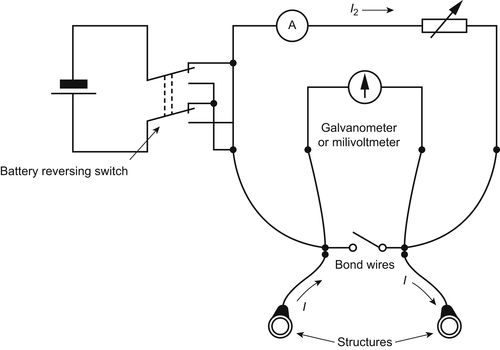
Type E—Line current measurement test point
This type should consist of two pairs of cables, each pair connected to the pipeline 30–60m apart. All cables should be separately terminated in a common test box (type 1) with suitable facilities. The cables should be identified by color coding or tags.
7.5.6. Installation of Test Box(es)
The test box(es) internally equipped with a copper bus bar, copper links, copper terminals, and a proper rotary resistor should be installed for the following purposes:
1. Connection of anodic cables (header cable and positive cable) between ground bed and positive pole of transformer/rectifier, and control of the ground bed current through the rotary resistor circuit (as a positive test box).
2. Connection of cathodic cables (negative cables) between the structure and negative pole of transformer/rectifier, and control of the CP system (as a negative test box).
3. Bonding between different cathodic circuits.
The box(es) should be installed in accordance with standard drawings.
7.5.7. Earthing of CP Equipment
The object of electrical earthing is to ensure effective operation of the transformer/rectifier in the event of earth fault current, which might otherwise cause damage to property, and protect against danger to life through shock due to the installation metal work being maintained at a dangerous potential relative to earth.
Local earthing circuit should be installed at the CP station(s), in accordance with 6.2.8.3 and as detailed on the standard drawings.
Each earthing system will be composed of the following:
• Earthing pits for connection and inspection of the copper rods.
• Copper rods inserted in the earth.
• Bonding header cables between the pits.
• Earthing cables from header cable to CP equipment and fence.
The requirements for the connection of metal works of CP station(s) are specified in the following:
BS 7430 (1991) “Code of Practice for Earthing”
Formerly C.P. 1013 (1956)
BS 6651 (1985) “Code of Practice for Protection of Structures Against Lightning”
The following are to be noted:
1. Earthing should be installed fully underground.
2. Earthing should be carried out at locations where the soil resistance is the lowest. Sandy soil should be avoided.
3. The grounding resistance should be kept as low as possible by adding salt, coke, or any other kind of backfilling.
If CP station(s) to be installed inside the area with individual earthing system, such as compressor station, valve station, and city gate station. The CP equipment should be adequately bonded together and connected to the existing earthing system.
In the absence of earthing drawings, CP equipment should be adequately bonded together and connected to the earth electrodes.
7.5.8. Fencing
Fencing should be erected by competent laborers, experienced in industrial-type fence erection.
Particular care should be taken during fence erection so that no underground piping, cable, or other appurtenances are touched or damaged.
On completion of the work, all excess and waste materials resulting from fence construction should be removed from the site by the contractor.
7.5.9. Parallel Power Lines
If the pipeline runs in the vicinity of high-voltage power lines, the contractor should investigate whether high AC voltages can be present on the pipeline by induction or otherwise and whether devices have to be installed for protection of the pipeline and personnel.
The contractor should show (by calculation or otherwise) that no harmful voltages will be present or design additional facilities to prevent excessive voltages. Such facilities may consist of dedicated pipeline earthing and/or the installation of polarization cells or surge arrestors across isolating joints/flanges and across the output terminals of DC voltage sources.
7.5.10. Lightning Protection
In areas of lightning activity, the contractor should install suitable lightning protection to protect the pipeline isolation and CP equipment. This should consist of suitably rated surge arrestors. Surge arrestors should be mounted across isolating joints/flanges and across the output terminals of DC voltage sources.
7.5.11. Surge Arrestors
Surge arrestors required to prevent elevated voltages due to faults in adjacent electrical power systems or lightning should be of the spark gap type and should be such that the following are criteria met:
• The impulse breakdown voltage of the electrodes is lower than that of the isolating joint across which they are mounted.
• The spark gap is capable of discharging the expected lightning currents without sustaining damage.
• The spark gaps are fully encapsulated to prevent sparks in open atmosphere and to protect the spark gaps from moisture.
7.6. Installation of Galvanic Anode Systems
Anodes should be installed according to design specifications and drawings. Before the anode is buried, it is important that any waterproof wrapping material be removed. Typical galvanic anode installations should be of the following types:
7.6.1. Single Packaged Anode
Anodes should be installed at a minimum distance of 1.5m from the pipeline and at least 30cm (1ft) deeper than the pipeline.
The native earth should be thoroughly tamped around the anode, watered, and then backfilled to the surface (after making all anode lead connections and insulating them).
Anodes should be placed 2m away from any secondary buried structure, so that the secondary structure does not lie between the anode and the primary structure.
In distribution systems, where space limitations are extremely critical and where soil resistivities and auguring conditions permit, anodes should be placed in auger holes alongside the pipe with the hole being deep enough that reasonable spacing between pipe and anode is obtained.
7.6.2. Multiple Galvanic Anodes
In multiple galvanic installation, anodes should be placed in a straight-line configuration for the lowest resistance to the earth. The line of the anodes may be either perpendicular to the pipeline, or may be along a line parallel to the pipe.
A Parallel line of magnesium anodes should be about 5m away from the pipeline, with zinc; this distance should be about 3m for optimum performance.
Where anodes and backfill are provided separately, anodes should be centered in the backfill, and the backfill should be compacted before any additional backfill soil is added. The backfill should be thoroughly wetted before burial is completed.
The connection to the pipe should be made before more than one anode is installed; it will then be possible to observe the current output of successive anodes as they are connected, and installation should be halted before the average output per anode falls below 150% of the designed value.
One 0.01-ohm measuring shunt should be installed; in each lead wire, current limiting resistors are not permitted.
The anodes thus installed should be permitted to operate unrestricted for a period of three weeks or more. This will permit adequate polarization and stabilization of current output. After this time, a current output and pipe-to-soil potential survey should be made. Resistors should be installed where needed, and the current should be reduced to the designed value. It is particularly important to check the potential at the midpoints between stations (if they are unequal in size, then at the low point). If these potentials should all be found to be >0.85, then the installation is said to be complete.
7.6.3. Extruded Ribbon Anodes
Extruded ribbon anodes (of either magnesium or zinc), should be plowed-in parallel to the pipeline along sections of bare or poorly coated lines where continuous local protection is required.
Connections between the pipeline and anode core wire should be made at intervals to complete the protection circuit. The crossconnections should be made at test points at a convenient location, to measure current flow periodically and estimate the rate of anode material consumption. Intervals between crossconnections should not be >300m.
Spacing between the ribbon anode and pipeline is not critical. To remain clear of the pipe during plowing-in operations, a spacing of 1.5m may be used.
The anode strip should be deep enough to be in continuously moist soil (at least 0.6m).
Extruded ribbon anodes of magnesium (or zinc) are furnished bare. Using anodes in the earth without a special backfill involves the risk of anode passivation and inadequate amounts of current. The anodes should be plowed-in with suitable special backfill according to the design specification. An adequate allowance for satisfactory dispersion around the anode is 32kg of backfill per 30m (100ft) of ribbon anode.
7.6.4. Connection of Galvanic Anodes to the Pipeline
The anodes should be connected to the pipeline using the combined marker, test point, and bond box. This equipment should be made for the following purposes:
• Pipe-to-anode ground bed connection;
• Pipe-to-soil potential measurement;
• Installation of a rotary resistor between anodes and the pipeline to allow the anode current control;
• Marking the location of the anodes.
Anode lead wire should be connected to a loop shaped cable (called header cable), using a suitably sized split bolt (line tap) or compression-type connectors and a proper branch type (3 way) splicing kit. The splicing compound should be applied over the tightened zero resistance connection.
The coated splice should be insulated by taping with at least one half-lapped layer of rubber tape and one half-lapped layer of electrical insulating tape, with the joint insulation overlapping the wire insulation by a minimum of 50mm.
The current-carrying cable is composed of two sections in black color: One section will connect the header cable to terminal No. 1 of “Combined Marker, Test Point, and Bond box,” the other section connects the pipeline to terminal No. 2.
A test wire should be connected between the pipeline and terminal No. 3 at “Combined Marker, Test Point, and Bond box.”
Thermit welding (cad welding process) should be used to connect the anode lead wire to the pipeline.
The copper wire connection to the steel main is the most critical insofar as insulation is concerned. At this point, all copper at the connection must be coated completely to avoid the possibility of a shielded copper–steel corrosion cell.
All connections must be permanently of a low resistance. Any gradual development of joint resistance can reduce the anode output.
Insulation of underground connections on galvanic anode installations should be well done to prevent current wastage. The connection should be waterproofed completely to prevent the possible development of resistance within the joint.
Care should be taken so that lead wires and connections are not damaged during backfill operations. Lead wires should have enough slack to prevent strain. Anodes should not be carried or lowered into the excavation area by the lead wire.
The following are to be noted:
1. The chemical backfill in packaged galvanic anodes will take up moisture slowly even if wetted with water after placing in the auger hole and before completing the earth fill. For this reason, the anode will not attain full output immediately. Depending on the amount of moisture in the earth, it may be a matter of days or even weeks before the full output is attained.
2. When bare galvanic anodes are placed in auger holes and backfilled with a separate chemical backfill, it is the usual practice to install the backfill dry. There will be a time lag before the full current output is attained as in the case with packaged anodes. It is possible to mix the chemical backfill with water and pour the slurry into the auger hole to surround the anode. The full output will be attained immediately. There is, however, the danger of shrinkage as the excess water leaves the slurry. This shrinkage may operate to cause the ultimate reduction in current output. Backfill installed dry, on the other hand, tends to swell upon taking up moisture to develop maximum coupling between the anode and the surrounding earth. For this reason, the use of dry backfill is considered the best practice.
7.7. Installation of CP Systems for Compact Buried Structures
This section outlines the procedures for the installation of CP systems for the of external surfaces of compact buried structures, including tank farms, service station tanks, tower, footings, steel pilings (in soil), short well casings, compressor and pump stations, refineries, petrochemical plants, and associated pipework.
The installation of CP systems for compact buried structures is basically similar to the installation of buried pipelines, so many of the requirements outlined in the previous section in respect of buried pipelines are applicable to compact buried structures, with the following exceptions:
1. Before any work is carried out on or near an insulated flange, the area should be checked for hazardous atmospheres.
2. To avoid the risk of electric shock and the possibility of sparking, it is advisable that insulating joints be crossbonded before being disassembled. This precaution is essential for hydrocarbon product lines.
3. Galvanic anodes should preferably be sited on a line normal to the long axis of the tanks at a distance of about 5m from the outside surface of the tank; if two anodes are used, one should be positioned on each side of the tank. For a well-coated tank, the siting of the anodes is not critical, and they may be sited to suit conditions, at a distance of approximately 3–6m from the tank.
The anodes should be buried at a depth that places them in permanently moist soil if possible.
The lifting lugs situated at either end of the tank provide convenient points of attachment for anode cables. The lugs should be scraped carefully to expose the bare metal, and the cable end should be attached by a bulldog clamp or by thermit welding; the coating should then be made good.
For tanks that are already buried, the cable can be connected to the vent pipe.
The cables from the tanks should preferably be connected to the cables from the anodes via a test box, including a measuring wire from the tank to enable periodic checks of the steel-to-soil potential to be made, as well as current measurements of the anodes.
4. Impressed current ground beds should be arranged symmetrically around a tank or group of tanks. Dependent upon the space available, the ground beds should be located not less than one tank diameter from the tank periphery to provide optimum current distribution over the tank bottom. If this is not possible, consideration should be made to distribute a number of anodes or ground beds evenly around the periphery of the tank or to install borehole ground beds. The top anode of a borehole ground bed should be at a minimum depth of 10m to facilitate current distribution.
If flammable liquids are being stored in the tanks, the preferred siting of the ground beds is outside of the bund walls. Where this is not possible, the ground beds and all connections should either be totally buried or, if above ground, comply with the requirements of the electrical classification of the hazardous area. This should also apply to any negative drain point connection to the tank. If borehole ground beds are used, any steel casing should be finished below the ground level to ensure that any spark hazard due to inadvertent contact between the casing and protected steelwork cannot occur.
7.7.1. Structure Preparation (to be Considered by the Structural Constructor)
The tank foundation mound should as far as possible be constructed so that it will distribute protection current uniformly to the whole of the underside of the tank. This means that the use of rubble, rock fill, etc., should be avoided and the mound should consist of fine-grained and well-compacted material, to a minimum depth of 150mm.
Storage tank bottoms are generally constructed by lap welding individual plates and are therefore electrically continuous. Where groups of tanks are to be cathodically protected, provision should be made for bonding between individual tanks.
If it is desired to confine the protection current to the tanks; isolating joints should be installed in all pipelines and fittings connected to the tanks including electrical and instrumentation connections.
If flammable liquids are being stored, such joints should be located outside the tank bund. Earthing electrodes connected to the tank should be of zinc, stainless, or galvanized steel.
7.7.2. Installation of Permanent Reference Electrodes
If the installation of the metallic structure is likely to obstruct correct electrode placement, permanent reference electrodes should be installed immediately prior to construction. For large structures, consideration should be given to installation of reference electrodes and associated cabling prior to the laying of foundations. Cabling should be laid with sufficient free play to allow for foundation movement and structural loading.
Reference electrodes should be installed as close as possible to the buried structure without touching or shielding the surface. The backfill around the electrode should have a resistivity not greater than that of the soil surrounding the buried structure. Allowance should be made for foundation settling when locating reference electrodes.
Where reinforced concrete foundations are to be laid, care should be taken to ensure that all reference and test point cabling and equipment are electrically isolated from metallic reinforcement materials.
Reference electrodes, associated cabling, and connections should all be checked for damage prior to installation. Correct operation and electrical isolation of the system should be confirmed prior to the final reinstatement of backfill material.
The actual location of permanent reference electrodes and cabling should be accurately documented on the as-built drawings.
7.7.3. Installation of Insulating Flanges, Joints, and Couplings
All insulating flanges, joints, and couplings should be installed in accordance with the requirements outlined in the standards.
The assembly of an insulating flange requires particular care, to ensure that insulation is not lost due to mechanical failure of the components.
It is to be noted that the use of resistance methods to determine the integrity of insulating flanges in the field can produce unreliable results.
Completed flanges should be coated in accordance with design specifications.
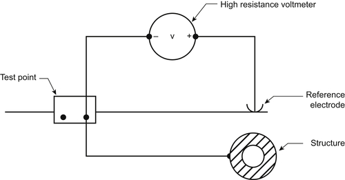
Insulating joints should be checked for insulation integrity by measurement of structure-to-soil potential on each side of the joint, with the reference electrode in the same location. Different potential readings indicate adequate insulation. If the potential readings are the same, a CP current (or changed CP current) should be applied to one side of the joint, and the potential should be remeasured. If the potentials remain the same on both sides, the joint is not adequately insulating.
7.8. Installation of CP Systems for Internal Surfaces
This Clause outlines procedures for the installation of CP systems for internal surfaces of pipes and structures, including heat exchangers, hot water systems, clarifiers, ballast and water storage tanks, cooling conduits, and reservoirs, that are in contact with natural waters including sea water and waters of near neutral pH.
Full construction details and installation procedures of the CP system for each specific type of structure will be specified in design specifications and drawings.
Many of the requirements outlined in previous sections in respect of buried pipelines are applicable to internal surfaces.
The installer should be thoroughly familiar with the specifications for the work, and should ensure that all work is completed in accordance with good industrial practice and the relevant specifications. Departures from design specifications should be approved by the designer and/or Company and permanently recorded for future reference.
Care should be taken to ensure that cables and other components are protected from damage during installation. All cable connections need to provide reliable long-term low-resistance electrical contact.
7.8.1. Materials and Equipment Acceptance (or Compliance)
Impressed current anodes should be provided with individual lead wires to the rectifier for control and measurement of current output from each individual anode.
Because anode cables may be subject to attack from a high chlorine environment found near some anodes, it is important that the cable insulation and sheathing be resistant to such an environment, or otherwise be suitably oversheathed or protected.
7.8.2. Installation of Impressed Current Systems
Impressed current anodes should be installed in accordance with design specification and drawings.
Impressed current anodes should not be directly attached to the internal part of the structure. They are required to be insulated from the structure and, in all cases, the electrical connection is to the positive terminal of the DC power source.
Because anodes are often brittle or have thin film electrodeposited coatings, care should be exercised to ensure that they are not damaged during handling.
Certain anodes are specifically designed for suspension by their cable tails, and may be lowered into position by the cable. Other anodes generally of the direct immersion type may require to be lowered into position by separate ropes, as their cable tails are designed for electrical purposes only and not for mechanical suspension. The installation drawings should be checked before the commencement of anode installation.
The following are to be noted:
1. Anodes that are in close proximity to a coated steel structure should be provided with an adequate dielectric shield, designed so that the potential at the periphery of the shield does not exceed −1.2V with reference to a copper/copper sulfate electrode.
2. In the case of cantilever anodes, which are generally rod shaped and project from the structure, obstruction of the active anode surface can be avoided by using an adequate shroud length to prevent the build-up of a calcareous deposit on the structure surface.
3. For safety reasons, suspended anodes, other than light anodes of platinized titanium or mixed metal oxides that are specifically designed to be suspended by their cable tails, should be supported by a suitable rope of polypropylene, to prevent the anode cable from bearing the anode weight.
Cable supports should be corrosion resistant and located so that the cable insulation does not become abraded due to cable movement from wind or electrolyte forces. Cable routes should also avoid areas of likely damage from physical operations on the structure.
Cable joints should be completely waterproofed using an appropriate cable-jointing compound. Waterproofing is particularly important on the positive side of an impressed current system to prevent localized rapid corrosion and subsequent failure of the corrosion protection system.
The following are to be noted:
Proper cleaning (degreasing and abrading) of the insulation is necessary to ensure that a watertight bond is achieved between the insulation and the cable-jointing compound. Where repairs are carried out, a minimum of 50mm of cable insulation should be applied to each side of the repaired cable joint.
Anode-to-cable tail encapsulation for immersed anodes is generally fitted at the factory. Prior to installation, the encapsulation should be carefully inspected for any faults or handling damage during transit.
Anodes that project from support pipes or require centering through insulating sleeves may require inspection after installation.
The following are to be noted:
Of special importance to be inspected during the installation is to ensure that the anode material and size are in accordance with the relevant standard, where applicable and/or to the approved specifications.
Warning:
Where underwater diving inspection or maintenance is likely, structures should have warning notices displayed advising of the danger of electrical gradients near the anodes and the need to switch off the system prior to diving.
Caution:
Signs should be displayed indicating the presence of any immersed cables or anode support ropes that are not physically protected.
Anodes and their support cables on structures located in flowing fluids should be designed to withstand vibration and impact.
Requirements of this standard and local authorities should be observed during the installation of a transformer/rectifier especially with regard to AC input, cabling, and positioning.
After installation of a unit, it is important that the following be checked:
1. The input and output terminals are correctly identified, and the structure cable is connected to the negative output terminal prior to connection to the electricity supply.
The following is to be noted:
When electricity is connected, correct polarity and loop resistance should be verified by energizing the unit, and checking that the structure potential is shifted in the negative direction.
2. The oil level is correct (if the unit is oil cooled).
3. The fuse ratings are correct.
7.8.3. Safety Precautions
Precautions must be taken to avoid the following:
1. The effects of lightning, both on the protected structure and via the electricity distribution system (personnel protection aspects should also be included), should be taken into account.
2. Electrical gradients resulting from impressed current systems occurring in water around fully and partially submerged anodes and in waterways adjacent to anode installations should be considered.
The following are to be noted:
Paralysis and respiratory failure may result if a person comes into contact with electric field strengths >3V/m in water. Should the design result in a possible electric field strength exceeding this value in waters located close to impressed current anodes, warnings should be given and access to such areas prevented by shielding or by other means.
3. Sparks in the presence of flammable substances and explosive gas mixtures that may be present around oil treating vessels should be avoided.
4. The cable-to-anode connections in impressed current systems should never be disconnected, nor should the anode be removed while the rectifier is in operation.
5. Usual precautions to prevent fire or explosion must be taken before a CP system can be installed or repaired in a vessel handling water mixed with oil or gas.
6. The rectifier case, external AC disconnect switch box, and any related metallic equipment must be properly grounded using recognized safe grounding practices.
7. Special gaskets capable of withstanding high temperatures should be used to mount anodes in fired vessels, particularly if the gaskets are located near fire tubes.
7.8.4. Installation of Galvanic Anode Systems
Anodes should be installed according to design specification and drawings.
The common methods of installation of galvanic anodes are as follows:
1. by direct attachment to the internal part of the structure; or
2. by suspension in the electrolyte from the structure using a cable or a rigid metal support; the cable is connected to the structure above electrolyte.
The following are to be noted:
For safety reasons, suspended anodes should be supported by a suitable rope of polypropylene to prevent the anode cable bearing the anode weight.
Anodes that are to be installed flush with the structure may be attached to the structure by either of the following methods:
1. Welding of the anode core to the structure.
2. The use of structure studs nuts to attach the anode core.
In all cases, the anode should be in reliable long-term low-resistance metallic contact with the structure. This may be achieved by the use of fusion joints, bolted connections, or by direct screwing into the structure surface. Ensure that corrosion resistant materials are used and the joints are effectively insulated (wrapped).
Before immersion of the anodes, it is necessary to remove any material wrapped around them. The anodes should not be painted and, where necessary, should be protected from accidental paint application.
Adequate support of anodes is necessary to avoid possible cable failure.
7.8.5. Permanently Installed Reference Electrodes
If permanent reference electrodes are installed for the measurement of the structure-to-electrolyte potential, it is important that they be continually immersed when in use.
Reference electrodes should be located in accordance with the design requirements. Each reference cell should be wired to a termination position by a separate and isolated conductor, insulated from the structure and the electrolyte, and protected by continuous conduit. Separate conductors can be installed together using a multicore cable.
It is essential that reference cell wiring be electrically shielded between the structure exit point and the termination position.
The most convenient method of mounting reference electrodes inside a plant is by means of a “screw-in” assembly such that the electrode can easily be withdrawn for inspection and replacement of either the entire unit or the electrode material. The electrodes can be wired to central monitoring and control equipment. A disadvantage lies in the difficulty of checking the accuracy of the electrodes, once installed.
If it is impossible to use “screw-in” mountings, reference electrodes can be attached by suitable nonmetallic fixings to the protected surface and the insulated connecting leads brought out through the plant wall through a suitable gland.
At least one reference electrode should be installed for each cathodically protected compartment. The reference electrode should be installed at the position where corrosion is most likely, for example at junctions of ferrous and nonferrous materials and/or remote from anodes.
The following are to be noted:
1. Care must be taken in placing the reference electrode in the treating vessel. For potential measurements the electrode must be as far from the anodes as possible. In pressure vessels, the electrode is “Lubricated” (introduced into the vessel against existing vessel pressure) through a gate valve installed in the vessel for that purpose.
2. Contamination of the reference electrode with oil or sediments such as iron sulfide must be avoided. A salt bridge may be used to prevent contamination of the reference electrode.
3. Location of the reference cell near an anode may indicate a higher potential than elsewhere in the vessel.
7.9. Installation of CP Systems for Marine Structures
This section specifies general construction requirements for the installation of CP systems that will control corrosion of the submerged zones of marine structures and the buried parts of integral offshore/onshore structures.
Full construction details and installation procedures of the CP system for each specific type of marine structure will be specified in design specifications and drawings.
Many of the requirements outlined in Clause 6 in respect of buried pipelines are applicable to submarine pipelines.
CP systems installed onshore to protect submarine pipelines should comply with Clause 6 of this Standard.
The contractor should be thoroughly familiar with the specifications for the work, and should ensure that all work is completed in accordance with good industrial practice and the relevant specifications. Departures from design specifications should be approved by the design engineer and/or company and permanently recorded for future reference.
It is necessary that precautions be taken in combustible atmospheres to prevent sparking due to potential differences between protected and unprotected structures. Any insulated devices should be crossbonded before being separated, and the CP system switched off.
Care should be taken to ensure that cable and other components are protected from damage during installation. All cable connections need to provide reliable long-term low-resistance electrical contact.
7.9.1. Immersed Structures
7.9.1.1. Installation of Impressed Current Systems
The installation should be done under the supervision of a corrosion specialist to verify that the installation is made in accordance with design specification and drawings.
Impressed current anodes should be installed in accordance with design specifications and drawings. Special care should be taken to avoid damage to anodes and their lead wires during installation. Careful supervision of this phase is most essential to proper long-term performance of the CP system.
Impressed current anodes may be installed by one or more of the following methods:
1. Anodes may be lowered in a casing and are allowed to extend below a termination fitting at the bottom. This method provides a means of anode retrieval or replacement without diver assistance.
2. Anodes may be installed on platform members using offset steel structural supports attached to the platform members. Diver assistance is required for anode replacement.
3. Anodes may be installed on the sea bottom floor, remote from the structure. The anodes may be supported by concrete foundations and buoyancy tanks to minimize the possibility of the anodes becoming covered with mud.
Because anodes are often brittle or have thin-film electrodeposited coatings, care should be taken to ensure that they are not damaged during handling. Certain anodes are specifically designed for suspension by their cable tails and may be lowered into position by the cable. Other anodes, generally of the direct immersion type, may need to be lowered into position by separate polypropylene ropes, as their cable tails are designed for electrical purposes only and not for mechanical suspension. The installation drawings and the recommendations of manufacturer should be checked before commencement of anode installation.
Cable supports should be corrosion resistant and located so that the cable insulation does not become abraded due to cable movement from wind or water forces. Cable routes should also avoid areas of likely damage from physical operations on the structure.
Cable joints should be completely waterproofed using an appropriate cable-jointing compound. Waterproofing is particularly important on the positive side of an impressed current system to prevent localized rapid corrosion and subsequent failure of the CP system.
The following are to be noted:
Proper cleaning (degreasing and abrading) of the insulation is necessary to ensure that a watertight bond is achieved between the insulation and the cable-jointing compound. Where repairs are carried out, the encapsulation should include a minimum of 50mm of the cable insulation on each side of the repaired cable joint.
Anode-to-cable tail encapsulation for immersed anodes is generally fitted at the factory. Prior to installation, the encapsulation should be carefully inspected for any handling damage during transit. Anodes that project from support pipes or require centering through insulating sleeves may require diver inspection after installation.
Where underwater diving inspection or maintenance is likely, structures should have warning notices displayed advising of the danger of electrical gradients near the anodes and the need to switch off the system prior to diving.
Signs should be displayed indicating the presence of any immersed cables or anode support ropes that are not physically protected.
Of special importance to be inspected during the installation is to ensure that the anode material and size are in accordance with relevant parts of available standard where applicable and/or to the approved specifications.
Conductor cable connections to the rectifier, from the anode(s) and the structure, must be mechanically secure and electrically conductive. Before energizing the power source, verify that the negative (−) conductor is connected to the structure to be protected, that the positive (+) conductor is connected to the anode(s), and that the system is free of short circuits. After the DC power source has been energized by authorization of the supervising corrosion specialist, suitable measurements should be made to verify that these connections are correct in polarity.
Connections between the positive header cable and lead wire(s) from the anode(s) should be mechanically secure and electrically conductive. The connections must be sealed to prevent moisture penetration and ensure electrical isolation from the environment. Submerged connections require seals suitable for the water pressure and environment to which they may be subjected.
When installing a suspended anode, where separate suspension is required, care should be taken so that the lead wire is not in such a tension as to damage the anode lead wire or connections.
Requirements of this Standard and local authorities should be observed during the installation of a transformer/rectifier especially with regard to an AC input, cabling, and positioning. Rectifier or other power source should be installed out of the way of operational traffic and remote from areas of extreme heat or likely contamination by mud, dust, water spray, etc. Where two or more rectifiers are installed, they should be spaced for proper flow of cooling air.
Wiring to rectifiers should comply with any applicable regulatory codes and with the operator's specifications. An external disconnect switch in the AC wiring to the rectifier should be provided.
Testing of the power source should be carried out to ensure adequate electrical connection and that no damage has occurred during installation.
The cables and connections should be carefully inspected to detect insulation defects. Defects should be properly repaired.
7.9.2. Installation of Galvanic Anode Systems
Anodes should be installed according to design specification and drawings.
Various methods for fixation of anodes to the object to be protected may be employed. The method employed should be based on an evaluation of the design requirements to electrical connection, loading, and stresses in the parts to which the anodes are attached.
The common methods of installation of galvanic anodes are as follows:
1. By direct attachment to the structure before structure immersion.
2. By direct attachment to the structure after structure immersion.
3. By placing the anode on the sea bed and connection to the structure by cable, either above or under water level.
4. By suspension in the water from the structure via a cable or a rigid metal support, and connection of the cable to the structure above water.
In all cases, the anode should be in reliable long-term low-resistance metallic contact with the structure. This may be achieved by the use of fusion joints or bolted connections using corrosion-resistant materials followed by effective insulation (encapsulation) of the joints.
Before anode immersion, it is necessary to remove any wrapping material. The anodes should not be painted and, where necessary, should be protected from accidental paint application.
It should be aimed at minimizing the drag forces caused by the sacrificial anode system.
Provisions for in-service installation of future additional current capacity should be made. Such provisions may include spare j-tubes for additional impressed current cables. Other provisions may be “pig tails” on pipelines and various sorts of brackets, guides, etc.
The anodes should be attached to the structure in such a manner that they remain secure throughout the service life.
The anode core should be welded to the structure either directly (e.g., on offshore structures) or by a cad-welded cable between the core and the structure is used (e.g., for bracelets around pipelines).
The distance between the anode and the structure depends on the condition of the structure. For coated steel, the minimum distance is zero; for a bare structure, the minimum is 25cm. The maximum distance is not critical provided the ohmic resistance of the interconnection is small compared with the anode resistance in the medium.
Underwater installation of anodes may be performed with mechanical fixing devices or by welding. Where the latter is done, welding should be performed in a dry environment provided by a hyperbaric chamber. Wet welding should only be allowed on members where cracks and defects will be harmless. Mechanical fixing devices may not give reliable electrical connections for >5years.
Where separate suspension is required, care should be taken when installing a suspended anode to ensure that the lead wire is not in sufficient tension to damage the anode lead wire, its insulation, or connections.
All galvanic anode installations should be tested to ensure that electrical continuity exists between the anode and the structure.
7.9.3. Electrical Connections
Electrical connections between anodes and steel structures should be made by manual welding or by thermit welding.
For pipelines and risers, attachment welding should be placed at least 150mm off other welds.
Doubler plates should be used for attachment of anode supports to pressurized parts and highly stressed structural members. Anodes should not be located in areas with high stress concentrations, for example, anode joints.
Doubler and/or gusset plates should be installed on anode supports at the time of anode installation. If installed as part of the anode fabrication, these plates are subject to serious damage during anode hauling and handling.
Suspended galvanic anodes should be installed after the platform is set on location offshore, and the anodes should be tested for good electrical contact to the structure after installation.
Welding of doubler plates and anode supports directly on to load carrying members and pressurized parts should be performed with a qualified welding procedure by qualified welders. These welds should be nondestructively examined as required for the welding of these components.
Attachments of electrical connections by thermit welding should be made using a qualified procedure proved to give sufficient bonding and negligible Cu-penetration along grain boundaries.
The size and the shape of the mold should suit the diameter of the pipe and the anode cable size.
Qualification of the thermit-welding procedure should be based on the visual examination and mechanical testing of three test welds.
The test welds should be sectioned and examined for bonding and possible excessive Cu-penetration using a microscope with a magnification of at least 100×. The Cu-penetration should normally be <0.3mm for procedures to be used on risers, while it will be a maximum of 0.8mm for procedures to be used on pipelines.
The hardness in the heat-affected zone should be determined on the macrosections and should be within the normal limit specified for the pipeline system.
Welds made between anode cores and structural members for offshore facilities should have the approval of the welding engineer. Procedure testing will often be required. Wet welding is not permitted.
Other methods used to connect anodes to structures are often used during retrofit exercises when welding is impossible. These are clamping, clamping plus hard-tipped bolting, flash stud welding in mini habitats, stud shooting, etc.
7.9.4. Corrosion Control Test Stations, Connection, and Bonds
Test leads to pipelines associated with offshore structures must be mechanically secure, electrically conductive, and should be readily accessible.
Both the pipe and the test lead wires should be clean, dry, and free of foreign material at the points of connection when the connections are made. The completed connection should be coated to prevent atmospheric corrosion.
Conductive connections to other pipelines or across insulating joints should be installed. All bond connections should be readily accessible for testing.
Steel piles should be electrically connected by means of a continuous copper cable embedded in the concrete deck, and connected to each pile by a welding process equivalent to cadweld or thermoweld. Fender piles should be electrically connected to the main pier structure by a flexible insulated cable.
Current continuity between sections of sheet piling should be provided by the joining of adjacent sections by welding a 25-mm diameter reinforcing bar across the joints at the time of installation.
Bollards should be installed in such a manner so as to prevent any electrical contact between them and the steel pier piling through the reinforcing bars in the concrete deck. This will minimize the possibility of temporarily depleting the CP of the piling when a ship is moored with steel cables.
7.9.5. Installation of Insulating Joints/Flanges and Devices
The assembly of an insulating flange requires particular care to ensure that insulation is not lost or damaged due to the mechanical failure of the components.
The following are to be noted:
The use of resistance methods to determine the integrity of insulating flanges in the field can produce unreliable results.
Completed flanges should be coated in accordance with design specifications.
Insulating joints should be checked for insulation integrity, for example, by the measurement of structure-to-electrolyte potential across the joint, with the reference electrode in the same location.
Different potential readings usually indicate adequate insulation. If the potential readings are the same, the CP current (or changed CP current) should be applied to one side of the joint, and the potential should be remeasured. If the potentials remain the same on both sides, the joint is not adequately insulated.
7.10. Submarine Pipelines
7.10.1. Installation of Impressed Current Systems
Impressed current anodes should be installed in accordance with design specifications and drawings.
The installation should be done under the supervision of a corrosion specialist to verify that the installation is made in accordance with design specifications and drawings.
Impressed current anodes submerged in sea water may be installed by one or more of the following methods:
1. Anodes may be lowered in a casing and are allowed to extend below a termination fitting at the bottom. This method provides a mean of anode retrieval or replacement without diver assistance.
2. Anodes may be installed on the sea bottom floor remote from the structure. The anodes may be supported by concrete foundations and buoyancy tanks to minimize the possibility of the anodes becoming covered with mud.
The anodes should not be mounted on sand and mud unless special precautions are taken to prevent them from being submerged as a result of tidal action.
When installing a suspended anode where separate suspension is required, care should be taken to ensure that the lead wire is not in sufficient tension to damage the anode lead wire, its insulation, or connections.
Rectifiers or other power sources should be installed so as to minimize the possibility of damage, vandalism, or unauthorized entry.
Wiring to rectifiers should comply with local and national electrical codes or requirements of utility supplying power. An external disconnect switch on AC wiring should be provided.
The conductor (negative lead wire) should be connected to the pipeline. Conductor connections to the rectifier must be mechanically secure and electrically conductive. Before the power source is energized, it must be verified that the negative conductor is connected to the pipeline to be protected and the positive conductor is connected to the anodes and that the system is free of shorts. After the DC power source has been energized by authorization of the qualified personnel responsible for corrosion control, suitable measurements should be made to verify that the connections and polarity are correct.
Connections between header cable and conductors from anodes should be mechanically secure and electrically conductive. All connections between anode lead wires and header cable should be insulated and sealed to prevent moisture penetration and to ensure electrical isolation from the environment.
Where the cables cross a beach, they should be buried in suitable backfilled trenches, with concrete slabs positioned over the cables to prevent movement or damage, or positioned and fixed in such a manner that cannot be moved or damaged by sea action.
7.10.2. Installation of Galvanic Anode Systems
Galvanic anode systems should be installed in accordance with design specifications and drawings.
It is important that the anodes be mounted in a manner so as to avoid mechanical damage during handling and installation of pipes. Anode bracelets should be fastened securely on the pipe. The two segments may be welded together with steel strips to ensure satisfactory mechanical connection and proper positioning. Each anode should be electrically connected to the pipe by at least two attachments, preferably one from each half bracelet. The reinforcement of concrete weight coating should not be allowed to be in electrical contact with pipe or anode.
Care should be exercised so as not to reduce the design surface area in contact with the electrolyte. This requirement is especially applicable to bracelet anodes where there may be a possibility of anodes being covered by insulating material or antibuoyancy material.
The contractor should acknowledge safe receipt of anodes in writing and should maintain records that should correlate anode identification with relevant pipe numbers. A copy of these records should be supplied to the Company.
The contractor should ensure that anodes are kept undamaged during all operations. Any damaged anodes should be segregated and reported to the Company.
Before an anode is immersed, it is important that any waterproof wrapping material be removed.
Anodes must not be painted and should be suitably protected during any painting operations.
Electrical connections for anodes are usually incorporated within the mounting arrangement. For bracelet anodes for pipelines, cable connections to the mounting steel framework are provided, and these must terminate on the pipe.
All galvanic anode installations should be tested to ensure that electrical continuity exists between the anode and the pipeline.
Anode bracelets should be installed as follows:
1. Exposed steel portions of the anode should be coated. The primer and dry film thickness of coating should be the same as that used in pipe coating.
2. The anodes should be placed centrally over the pipes and clamped tightly in place. The segments should then be welded or bolted together as indicated on the design drawings. Bolting material should not be high tensile and should be limited to a hardness of 300 vickers.
3. The coating should be removed from the areas where the bonding leads are to be welded to the pipe. The area must be cleaned to bright metal to ensure proper bonding of the weldment.
4. The bonding leads should be welded to the pipe by the thermit welding or an equivalent process. Attachment welds should be made using consumable and procedures qualified under fully representative conditions. The qualification should consist of one trial weld that should be sectioned and subject to a macroexamination and hardness survey.
The sections should show no cracking or copper penetration, and the hardness should not be >260 vickers.
5. Visual damage and holidays should be repaired in the primer coat on the bracelet. The coating over the weld and surrounding area of the pipe should be repaired.
6. The bracelet should be shielded with a light gage sheet metal or by other methods approved by the Company representative while installing the concrete coating. The concrete coating mesh should be cut back so that it will not be within 50mm of the anode. An ohm meter should be used to demonstrate to the Company representative that the reinforcement steel is not in contact with the anode.
7. Gaps between the anode bracelets and between the anodes and the concrete coating should be filled with concrete or mastic infill to produce a smooth surface across the bracelet with only the exterior curved surface of the anode exposed.
7.10.3. Corrosion Control Test Stations, Connections, and Bonds
Electrical continuity between the test point and the pipeline should be proven by means of a continuity tester, indicating zero resistance.
The test point should, where possible, be constructed prior to the application of the pipeline weight coating system, and care should be taken to ensure that all bare metal is insulated (except for the point of contact used for the test point).
Care should be taken to ensure that the reinforcement in the antibuoyancy weight coating material does not come into contact with the test point and that a minimum of 30-mm clearance between the reinforcement and the test point should be maintained.
Test points should be installed as required, but will be located midway between sacrificial anodes.
Connections of test lead wires to pipelines above the water must be installed so as to be mechanically secure and electrically conductive. Pipe and test lead wires should be clean, dry, free of foreign material, and properly coated.
Conductive connections to other pipelines or across electrical isolating devices should be mechanically secure, electrically conductive, and suitably coated. Bond connections should be accessible for testing.
7.10.4. Reinforcement
Pipeline weight coating reinforcement material should be carefully installed in accordance with standard specifications.
Each pipeline section should be inspected and tested using a 1000-V insulation test set to ensure that the reinforcement is not in contact with the pipe wall. A minimum reading of 1mega-ohm will be regarded as satisfactory.
After each joint has been completed, the pipeline section reinforcement should be insulation tested from the remote end; this will be applicable for both lay barged and bottom pull pipelines.
7.10.5. Pipeline Crossings
Where two or more pipelines cross, test points should be fitted to the pipeline and positioned to coincide with the crossing.
Where test points for bonding purposes have not been installed, a clamp arrangement with set screw should be utilized. Care should be taken not to damage the coating and the pipeline. The set screw should be tightened only sufficiently to make a good electrical contact but not to damage the pipe wall.
7.11. Electrical Measurements and Tests
Clause 10 indicates the apparatus needed and the techniques for measuring voltage, current, and resistance and for testing for the continuity of structures to ensure the successful commissioning of a CP installation. Some survey techniques are described.
Electrical measurements and inspections are necessary to ensure that the initial protection of the structure has been established in accordance with applicable criteria, and that each part of the CP system is operating satisfactorily.
It is important for subsequent system checks to be carried out to ensure that the structure remains protected and, if changes are noted, that action is taken to return the system to a protected condition.
Whenever be the surface of a structure exposed, the condition of the coating should be noted, and the coating repaired appropriately.
Under no circumstances should any CP system be energized before inspection and testing is completed.
7.11.1. Potential Measurements
• Instruments
All instruments used for determining electrical values should be of an appropriate type and of the required accuracy. They should be maintained in good working condition at all times.
Where fluctuations in the electrical measurements are noted, it may be necessary to substitute recording instruments for meters during surveys.
Electrodes other than copper/copper sulfate and silver/silver chloride may be used, provided that their relationship with these electrodes is either known or established prior to each measurement.
7.11.2. Potential Survey of Internal Protection of the Plant
With a fully enclosed plant, it is normally necessary to install permanent measuring points or reference electrodes. Where the positions at which measurement should be made can be predicted, these facilities are preferably installed before commissioning.
Alternatively, potential surveys can be carried out initially with temporary equipment to determine the positions where the potentials are most positive and whether the most negative potentials are acceptable.
• Permanently installed reference electrodes
The most convenient method of mounting reference electrodes inside a plant is by means of a “screw-in” assembly such that the electrode can easily be withdrawn for inspection and replacement of either the entire unit or the electrode material.
The electrodes can be wired to central monitoring and control equipment. A disadvantage lies in the difficulty of checking the accuracy of the electrodes, once installed.
For detailed potential surveys, or if it is impossible to use “screw-in” mountings, reference electrodes can be attached by suitable nonmetallic fixings to the protected surface and the insulated connecting leads brought out through the plant wall through a suitable gland.
Figure 7.1Zero resistance ammeter circuit used to measure current flowing in a bond (bond disconnected). With current Ib adjusted to give no deflection on the galvanometer Ib is equal to the bond current.
Generally, it is advisable to install at least one reference electrode for each cathodically protected compartment. The reference electrode should be installed at the position where corrosion is most likely, for example, at junctions of ferrous and nonferrous materials and/or remote from anodes.
7.11.3. Determination of Bond Resistance
It is necessary to determine the value of the resistance that should be connected in series with a bond, to adjust the structure electrolyte potential of a structure to a desired value. This can be done either by insertion of a series of fixed calibrated resistors until a suitable value is found or by adjustment by using a variable resistor, whose resistance is subsequently measured. Alternatively, if the galvanometer shown in Fig. 7.1 is calibrated to indicate voltage, the desired potential conditions on the structure can be obtained by adjustment of the resistor. The necessary resistance value is determined as the ratio of the voltage to the current. This arrangement has the advantage of obviating the need for low-resistance leads. Special milliohm meters are also available for measuring the very low resistance of bonds.
7.12. Tests Prior to Installation of CP on Buried or Immersed Structures
7.12.1. Soil/Water Evaluation
7.12.1.1. Soil/Water Sampling
• Soil samples may be obtained from along the pipeline route with a minimum of one sample from each type of soil noted to exist. Samples are to be ideally between 250 and 2000g and are placed in sealed, sterile, air-tight containers and should fill the containers completely.
• Where bacteriological analysis is to be undertaken, the soil sample is to be as little disturbed as possible and should completely fill the containers.
• Soil samples are obtained from depths either by excavation or by auguring techniques.
• Water samples may be obtained from rivers, estuaries, and water-logged locations. Samples need to be ideally between 1 and 2L; placed in sealed, sterile, air-tight containers; and need to fill the containers completely.
• In the case of immersed structures, any analysis of water samples should include measurement of the oxygen content and conductivity. It should be noted that, particularly in the case of estuarine waters, considerable variation can occur depending on the state of the tide and on the season. Moreover, stratification is often present, and the use of a suitable sampling technique is recommended.
• The analysis is to be completed with a minimum delay, from the time of sampling.
7.12.1.2. pH Measurements
• After resistivity measurements, pH measurement is perhaps the most widely used test for corrosivity. Where corrosion could be caused or enhanced by chemical attack, pH measurement may be used to assess this risk.
• The methods available for pH measurement include the following:
• glass electrode and millivoltmeter;
• colorimetric;
• indicator papers.
• Glass electrodes may be used with either potentiometric or high-impedance millivoltmeters. Both types are available as portable, battery-powered units for field use. Apparatus, reagents, and procedures are listed in both ASTM G51 and BS 1377.
• Colorimetric techniques are also described in BS 1377 and may be used as rapid field techniques. However, results can be erratic, and excessive turbidity in the soil may mask end point.
• Indicator papers are a practical site method and are sufficiently accurate for most survey purposes. Dry soils may be wetted with deionized water for this technique.
7.12.1.3. Soluble Salts
Chemical analysis for salts is usually restricted to chlorides, sulfates, carbonates, and sulfides. The latter two are analyzed qualitatively, and chlorides and sulfates are analyzed quantitatively. Quantitative analysis of chlorides and sulfates is undertaken by gravimetric, volumetric, or colorimetric (semiquantitative) analysis. The gravimetric and volumetric analysis of sulfates is detailed in BS 1881. For corrosion purposes, only the water-soluble sulfates are of concern, rather than total sulfates.
• A quick assessment of the resistivity of water may be made from the value of total dissolved solids by the following formula:
6250TotalDissolvedSolids=Resistivityinohm−m.
7.12.1.4. Bacterial Analysis
There are a number of microorganisms that thrive in or create conditions conductive to corrosion. These principle organisms are sulfobacteria, ferribacteria and sulfate-reducing bacteria. In soils, the most common form of bacterial corrosion is caused by sulfate-reducing bacteria. These bacteria are most active in anaerobic soils in which the hydrogen ion concentration is near neutral, that is pH 7.0, but are known to grow in the range pH 5.5–8.5. They act by converting sulfates in the soil to sulfides.
Various approaches exist to detect soils in which sulfate-reducing bacteria are likely to thrive. They are as follows:
• Redox potential
Redox potentials are measured in the field by measuring the potential of a platinum electrode using a reference calomel electrode. The reading is pH corrected.
The general accepted criteria for microbial corrosiveness as quoted in BS 7361 are as follows:
Redox potential 100mV: severe
Corrected to pH7 100–200mV: moderate
(mV Standard 200–400mV: slight
Hydrogen Electrode) 400mV: noncorrosive
This technique is probably the most widely used for assessing microbial activity. The reproducibility of results is however poor, and the equipment can only be used with confidence in relatively soft soils.
• Detection and enumeration
Detection of sulfate-reducing bacteria is undertaken by using one of a number of culture media that include Bars, Postgate, and American Petroleum Institute (API) media. Generally, the culture consists of a nutrient, an indicator, and a redox-poising agent with the pH adjusted to near neutral.
Enumeration is carried out by using a series dilution. After solidification of the culture medium and 2-day incubation, the colonies of bacteria can be counted.
• Chemical tests
These basically cover sulfate content, organic materials content, soluble iron, and hydrogen uptake of the soil.
7.12.1.5. Moisture Content
Moisture content of soils may be determined by one of the methods described in BS 1377.
A structure/electrolyte potential survey should be carried out to determine the structure/electrolyte potential variation along or over the surface of the structure.
Such a set of potential measurements may indicate those points on the structure where the worst corrosion is likely to be taking place.
With no applied CP, and in the absence of stray currents, the most negative structure electrolyte potentials indicate the corroding areas. On the other hand, if corrosion is due predominantly to stray current in the soil, the more intense corrosion will be associated with the more positive structure/electrolyte potentials.
7.12.3. Stray Electric Currents
Where the presence of stray electric currents is suspected, for example, in proximity to DC electric traction systems or where varying structure/electrolyte potentials indicate the possibility of such currents, it is necessary to determine more accurately the extent of stray current effect on the structure. This can be done by plotting the potential field in the area, using a stationary reference electrode, or a structure, as a reference point.
7.12.4. Tests for Electrical Continuity
Tests should be carried out whenever the continuity of the structure is in doubt, to locate any discontinuities.
7.13. Tests during the Commissioning Period
The structure/electrolyte potentials at various points on a structure will continue to change for some time after protection has been applied. Tests should, therefore, be made at intervals and currents should be adjusted as necessary until conditions become stable with potentials at all points not less negative than the values given in protection criteria.
A comprehensive survey should then be made, and the results should be analyzed to provide a list of conveniently carried out tests by which the continued satisfactory operation of the protection system can be confirmed.
Immediate action should be taken if abnormally positive changes in potential occur, particularly at the point(s) of application of current indicating that one or more transformer rectifiers have been reversed.
More frequent inspections (e.g., at monthly intervals) are recommended in the following situations:
1. the nonoperation of one transformer rectifier would result in a total or partial loss of protection;
2. the nonoperation of the transformer rectifiers is likely, due to factors outside the operators control, for example, known unreliable power supplies, joint operation with a third party, susceptibility to electrical storms; or
3. protection is provided by a single bond from another protected structure.
It is important that commissioning and routine test readings should be permanently recorded. In many instances, comparison with these provides the only information that is available as to the condition and performance of the system. To this end, a routine should be established for the periodic review of the measurements to ensure that the conditions are satisfactory. Consideration should be given to the computerization and graphical presentation of records, with the inclusion of exception reporting for test measurements that fall outside set limits.
7.13.1. Buried Structures
Structure/electrolyte potentials should be measured at a series of points including, particularly, points remote from the ground bed or anode positions.
Outputs should be adjusted to the minimum that gives the desired level of protection.
The period required for the potentials to become stable may vary from a few days for a well-coated structure to a few months for a bare or poorly coated structure.
Where possible, currents from individual sacrificial anodes or transformer-rectifier units should be measured. In the case of a complicated pipe system, it is also useful to measure the current flowing from individual branches or sections.
Once the operating conditions have been established, organizations that might be installing underground equipment in the area in the future should be given sufficient information for them to be aware of possible interaction problems. This will include, for example, ground bed positions and expected currents and, if not already provided, an indication of the routes of the protected structure and of any structures that have been bonded to it to reduce interaction.
7.13.2. Fixed Immersed Structures
Structure/electrolyte potentials should be measured, at the points provided, soon after the protection is switched on. Individual (or group) anode currents should be measured and adjusted to the minimum that gives protection.
The structure potential should be measured by connecting a high input-impedance voltmeter (at least 1M) to the structure, usually at a test point, and placing a reference electrode, connected to the positive terminal of the voltmeter, as near as practicable to the immersed surface of the structure (Figs 7.2 and 7.3).
Because accurate measurement of the structure potential requires the reference to be located at the surface of the structure, the reference electrode may be located by a diver, a remotely operated vehicle, or be permanently installed at various areas of the structure (e.g., areas of complex geometry or where shielding can occur). Such readings can then be related to readings taken with a reference electrode placed adjacent to the side of the structure.
Care should be taken to ensure that the structure component to which the measuring voltmeter is connected is not carrying a substantial CP current. With impressed current systems, in particular, parts of the structure may be carrying a large current and hence may cause a significant voltage drop error in the measurement.
7.13.3. Internal Protection of Plant
Structure/electrolyte potentials should be measured at the test points before and soon after the installation is switched on (Fig. 7.4). The currents at individual anodes (or groups of anodes) should be monitored and adjusted as necessary after a further period, for example, one week, then, if no serious departure is observed, again after one month. At each adjustment, the individual and total anode currents should be noted for reference.
Figure 7.2Structure potential measurement.
Figure 7.3Measurement of structure potential on fixed immersed structures.
Each sensing electrode used for automatic control should be checked against a suitable reference electrode installed close to it. Unless there is experience with a similar plant, reference electrodes should also be installed at a sufficient number of positions in the protected equipment to enable a representative potential distribution curve to be plotted. This will show whether the position of the sensing electrode was chosen judiciously and whether the correct control setting has been selected. If more than one sensing electrode provides the feedback signal to the controller, the readings on each should be compared for incompatibilities before and after switching on the protection. Readings may show differences due to the presence of electropositive materials, and the gradients around anodes. Ideally, all the sensing signals should be within 50mV when the protection is switched on. Slightly wider tolerances (e.g., 100mV) may still form an acceptable basis for control.
7.13.4. Internal Surfaces
The structure potential should be measured by connecting the positive terminal of a high-impedance voltmeter (at least 1mega-ohm) to the structure, usually at a test point. The negative terminal should be connected to a reference cell that is positioned as near as practicable to the immersed surface of the structure.
Figure 7.4Alternative methods for measuring structure potentials.
Because accurate measurement of the structure potential requires the reference to be located at the surface of the structure, the reference electrode may be carried by a remotely operated vehicle or be permanently installed at various areas of the structure (e.g., areas of complex geometry or where shielding can occur). Accurate readings of the structure potential can then be related to readings taken with a reference electrode placed adjacent to the side of the structure.
Care should be taken to ensure that the structure component to which the measuring voltmeter is connected is not carrying a substantial CP current. With impressed current systems, in particular, parts of the structure may be carrying a large current and hence may cause a significant voltage drop error in the measurement.
7.14. Specialized Surveys
There are a number of specialized survey techniques being utilized to provide additional detailed data concerning corrosion prevention systems.
These techniques would normally be carried out by specially trained personnel using purpose-built equipment and instrumentation, often only available from specialist contractors. These surveys are generally time consuming, but the information gained may not be available from other methods.
The surveys covered by this Standard are as follows:
1. Surveys for detecting external pipeline coating defects are
a. Pearson survey,
b. Electromagnetic current attenuation survey,
c. Close interval pipe-to-soil potential survey.
2. Surveys to determine the effectiveness of CP systems are