
Chapter 1. Firewall Overview
Refer to the following sections for information about these topics:
• 1-1: Overview of Firewall Operation—Discusses the mechanisms a Cisco firewall uses to inspect and control traffic passing through it. The firewall inspection engines and algorithms are responsible for enforcing any security policies configured into the firewall.
• 1-2: Inspection Engines for ICMP, UDP, and TCP—Describes how a firewall reacts to traffic of different IP protocols. The inspection mechanisms for the ICMP, UDP, and TCP protocols are covered.
• 1-3: Hardware and Performance—Provides an overview and comparison of the various Cisco firewall platforms and their specifications. This information can help you decide which firewall model is best suited for your application.
• 1-4: Basic Security Policy Guidelines—Presents a list of suggestions for configuring and maintaining firewalls in a corporate network.
A firewall has multiple interfaces, but it isolates traffic between each one. The simplest firewall configuration has one outside and one inside interface, as shown in Figure 1-1.
Figure 1-1 Basic Firewall with Two Interfaces
Each interface is assigned a security level from 0 (lowest) to 100 (highest). Multiple interfaces are each assigned an arbitrary security level, as shown in Figure 1-2.
Figure 1-2 Basic Firewall with Several Interfaces
A firewall is usually represented by the symbol of a diode, an electronic component that allows current to pass in only one direction. Flow in the direction of the arrow is allowed, whereas flow against the arrow is blocked. Other symbols also are commonly used to represent firewalls. Most of those involve a brick wall with or without flames.
Likewise, a firewall has the following default behavior:
• In general, outbound connections from a higher security interface to a lower one are allowed, provided that they are permitted by any access lists that are applied to the firewall interfaces.
• All inbound connections from a lower security interface to a higher one are blocked.
The default policies can be changed so that some outbound connections can be blocked and some inbound connections can be allowed. Also, firewall interfaces can be assigned identical security levels so that traffic is allowed to pass between them.
All traffic is inspected according to a suite of stateful firewall inspection processes and algorithms. These are commonly called inspection engines or application layer protocol inspection.
Note
Inbound and outbound connections refer to the direction in which a connection is initiated. For example, if a host on the outside tries to initiate a connection with an inside host, that is an inbound connection.
Keep in mind that an inbound connection is entirely different from traffic that returns in the inbound direction. Return traffic is allowed inbound through the firewall only if it is in response to a previously established outbound connection. The same is true for connections and return traffic in the opposite direction.
1-1 Overview of Firewall Operation
A firewall’s essential function is to isolate its interfaces from each other and to carefully control how packets are forwarded from one interface to another. In its default state, a firewall does not allow any packets to pass through it until some security policies are configured.
Before connections can form between firewall interfaces, two conditions must be met:
• An address translation policy must be configured between a pair of interfaces. (This requirement can be disabled with the no-nat-control command or Cisco firewall.)
• A security policy must be configured to allow the connection to initiate toward the destination. This is usually in the form of an access list applied to a firewall interface.
A Cisco firewall inspects traffic through a progression of functions. Figure 1-3 shows the order of these functions as a packet arrives at interface X (the left side of the figure) and exits at interface Y (the right side of the figure). The following sections describe each firewall function.
Figure 1-3 A Cisco Firewall’s Sequence of Packet Inspection Functions
Initial Checking
As packets arrive at a firewall interface, they are checked for basic integrity. One of the most important things that can be checked is the integrity of a packet’s source address. When a host sends a packet through a firewall, the firewall normally is concerned with finding a route for the destination address so that the correct egress interface can be used. The source address usually is ignored until the destination host needs to send a reply.
A malicious host can insert a bogus source IP address into the packets it sends. This is called address spoofing, and it is used to impersonate another host. When the malicious traffic is received, it looks like someone else sent it.
RFC 2827, “Network Ingress Filtering: Defeating Denial of Service Attacks which Employ IP Source Address Spoofing,” describes a method that a firewall can use to detect when a source address is being spoofed.
Note
You can find all RFCs online at http://www.ietf.org/rfc/rfcxxxx.txt, where xxxx is the number of the RFC. If you do not know the RFC’s number, you can try searching by topic at http://www.rfc-editor.org/cgi-bin/rfcsearch.pl.
A Cisco firewall uses this technique in its Unicast Reverse Path Forwarding (RPF) feature. When this feature is enabled on an interface, the source address in each incoming packet is inspected. The source address must be found in the firewall’s table of known routes, which in turn must reference the interface on which the packet arrived. In other words, the firewall just verifies that the packet would take the same path in reverse to reach the source.
The firewall drops any packets that do not meet the RPF test, and the action is logged. If the RPF feature is enabled, you should make sure any IP subnets that can be reached on a firewall interface are also identified with a route command on the firewall. That way, the firewall can find those source addresses for the RPF test (as well as send packets toward those destination networks).
The outside firewall interface is a special case, however. Usually, the firewall has a default route associated with the outside interface, because most of the public network or Internet can be found on the outside. How can a firewall check for address spoofing on packets arriving at the outside interface?
If a source address cannot be found in the table of known routes, the default route is assumed to match. Therefore, packets arriving from the outside pass the RPF test as long as the source subnet or a default route exists. If an outside host uses a spoofed source address that belongs to a host or subnet on another firewall interface, however, the firewall finds that the reverse path does not match.
In other words, RPF can detect spoofed addresses only when they are spoofed between interfaces. To do this, the firewall has to know that a spoofed address on one interface actually exists on another interface. Only those packets are dropped. However, if a host on the outside interface spoofs the address of another outside host, the firewall cannot detect it, because the spoofing occurs on a single interface.
Xlate Lookup
A Cisco firewall maintains a translation or xlate table for each protected host that can participate in connections. A host’s xlate entry can be statically defined before any active connections form. However, the static xlate entry is not actually created and used until the relevant traffic passes through the firewall. The host’s xlate entry can also be created dynamically as a new connection is initiated.
Figure 1-4 illustrates the concept behind xlate operation. A host outside the firewall (Host A) has a registered public IP address, called a foreign address. A host on the inside of the firewall (Host B) has an internal IP address, called the real or local address. The internal host’s address is translated through an xlate entry so that the local address appears on the outside of the firewall as a mapped or global address. Address translation is covered in greater detail in Chapter 6, “Controlling Access Through the Firewall.”
Figure 1-4 The Basic Concept Behind Xlate
Each entry in the xlate table is maintained with the following parameters:
• Protocol used (ICMP, UDP, or TCP)
• Local and global interfaces
• Local and global IP addresses
• Local and global port numbers (if applicable; UDP and TCP only)
• Idle timer (incremented if no packets have used the xlate)
• Absolute timer (incremented since the xlate entry was created)
• Uauth bindings (originating user if user authentication or cut-through proxy is used)
• Connections using the xlate entry:
— Number of connections
— Number of embryonic (not yet fully established) connections
— A list of the active connections
Xlate table lookups occur at different points in the inspection process, depending on the direction of the connection. For an outbound connection (initiated from the inside), the xlate entry must be created early in the sequence of events. This is because the translated (global) address is used to build the actual connection entry and is used as the reference point for any access control list (ACL) operations. For inbound connections, the opposite is true—any connections and ACL operations must look at the untranslated (global) addresses, so xlate lookup must occur late in the game.
A firewall controls several aspects of each xlate entry:
• The number of active connections allowed to use an entry can be held to a maximum limit or can be unlimited (the default).
• The number of embryonic connections attempting to use an entry can be held to a maximum limit or can be unlimited (the default).
• An entry is aged out of the table if it has been idle for a timeout period.
Conn Lookup
A Cisco firewall examines and keeps track of the state of each connection attempting to go through it. This is often called stateful inspection. If a connection is allowed to form (the access list permits the traffic flow), each state change is updated in the firewall’s connection or conn table. As soon as a connection initiates and a conn table entry is created, traffic from the source to the destination is allowed to pass. As well, the return traffic for that connection is allowed back through the firewall toward the source.
The connection state and the behavior of packets from the source and destination must follow the rules of the IP protocol being used. Any deviation from the accepted behavior causes the connection to be dropped and logged.
Each entry in the conn table is maintained with the following parameters:
• Protocol used (ICMP, UDP, or TCP)
• Local and foreign IP addresses (note that local addresses are used here, after the xlate lookup)
• Local and foreign port numbers (if applicable; UDP and TCP only)
• Flags for fixup type and connection state
• Idle timer (incremented if no packets have used the connection)
• Byte counter (total traffic volume using the connection)
• Local and foreign TCP sequence numbers
Conn entries are aged out of the table if they have been idle (no data passing through) for a timeout period. Conn entries can also age out after a short period if the connections are not fully established.
When Transmission Control Protocol (TCP) is used for a connection, a Cisco firewall can generate a random initial sequence number (ISN) toward the foreign host. Some hosts do not generate a truly random ISN, resulting in predictable values that can be exploited. The firewall can substitute a truly random ISN into the TCP packets when the connection is negotiated. This reduces the risk of session hijacking and is totally transparent to the local and foreign hosts.
ACL Lookup
Before a connection can be completed or actually allowed to form, its traffic must be permitted by an ACL. You can configure any number of ACLs in a firewall, but only one ACL can be applied to a firewall interface in a specific direction.
Note
Before ASA 7.0(1), ACLs could be applied in only the inbound direction, to inspect traffic as it enters the interface. In later releases, ACLs can be applied in the inbound or outbound direction. All releases of FWSM support ACLs in both directions.
ACLs are not used to inspect a connection’s state. Rather, they are used only to permit or deny packets in a single direction, only as connections are being initiated. For connectionless protocols such as Internet Control Message Protocol (ICMP), ACLs permit or deny all packets in the direction in which they are applied.
By default, no ACLs are configured or applied to any of a firewall’s interfaces. Connections are permitted to initiate from a higher-security interface to a lower one—even with no ACL applied to the higher-security interface. One exception is the Catalyst 6500 Firewall Services Module (FWSM), which requires an ACL on any interface before permitting traffic to pass. However, no connections are allowed to initiate from a lower-security interface to a higher one until an ACL is applied to the lower-security interface.
ACL configuration and use are covered in greater detail in Section “6-3: Controlling Access with Access Lists,” in Chapter 6.
Uauth Lookup
A Cisco firewall can authenticate users as they pass through to initiate connections. After a user is successfully authenticated, the firewall keeps the user credentials cached so that additional connections can be quickly approved. In other words, the firewall acts as a cut-through authentication proxy so that no further authentication is needed.
User authentication occurs by a request-reply exchange between the firewall and an authentication, authorization, and accounting (AAA) server, such as Remote Authentication Dial-In User Service (RADIUS) or Terminal Access Controller Access Control System Plus (TACACS+).
After a user is authenticated, the firewall can also request authorization information from the server. This information is used to limit users to reaching only specific resources through the firewall. The firewall can authorize users through one of the following methods:
• Retrieving a AAA attribute for the user
• Controlling the user’s connections with an ACL referenced by the AAA server
• Controlling the user’s connections with an ACL that has been downloaded from the AAA server
The firewall performs these functions by keeping a table of authenticated users and their user authentication (uauth) attributes. The uauth table records each authenticated user, along with his or her source IP address, the authorization ACL name (if any), and session timer values. In Chapter 5, “Managing Firewall Users,” Section “5-5: Configuring AAA for End-User Cut-Through Proxy,” covers AAA functions in greater detail.
After a user authenticates with the firewall, he can use and create new connections until his absolute uauth timer expires. As well, the firewall tracks to see if the user has not sent or received data on any of his connections for an idle uauth timer period. If the idle timer expires, that user is deleted from the uauth table, and all current connections are closed. That user is required to reauthenticate when he attempts a new connection. If the absolute timer expires, all the user’s existing connections are allowed to remain open. However, the user is prompted to reauthenticate when a new connection is initiated.
Inspection Engine
The firewall inspects each connection and applies rules according to the protocol being used. This process has traditionally been called fixup, and more recently an inspection engine or application layer protocol inspection.
Some protocols are simple and have very loose guidelines about the traffic between source and destination. These are called connectionless protocols, and they include ICMP and UDP. Other protocols are very strict about the handshaking and packet exchange between source and destination. These are called connection-oriented protocols, and they include TCP.
1-2 Inspection Engines for ICMP, UDP, and TCP
The following sections outline the basic stateful inspection of each type of applicable protocol.
ICMP Inspection
ICMP is a connectionless protocol, because it allows one host to send another host a message without expecting a reply. Because of this, a firewall cannot examine or track the state of ICMP traffic between two machines. However, beginning with ASA 7.0(1) and FWSM 3.1(1), a firewall can track the state of ICMP packet exchanges, offering an approximation of a stateful inspection.
A firewall must rely on some of its basic mechanisms for inspecting ICMP traffic—the xlate table and ACLs. Note that no connections are used with ICMP, so no conn entries are created for ICMP traffic. Figure 1-5 shows how a Cisco firewall reacts when it needs to handle ICMP traffic between two hosts on different interfaces.
Figure 1-5 How a Firewall Handles ICMP Traffic
Host PC-1 sends an ICMP packet to host PC-2. The firewall needs an xlate entry for one or both of the hosts. This is created from either a static xlate or a dynamic assignment, depending on the configuration. The ICMP packet must also be permitted by any ACL that is applied to the firewall interface toward PC-1.
As an example of this process, PC-1 (foreign address 172.16.1.100) tries to ping host PC-2 (global address 172.18.1.200). PC-2 has a static xlate entry that translates global address 172.18.1.200 on the outside to local address 192.168.199.100 on the inside.
The debug icmp trace command reveals debugging information for all ICMP traffic passing through the firewall. Similar information could be gathered from Syslog messages generated by the firewall. In this case, message IDs 305009, “Built static translation,” and 609001, “Built local-host,” might be seen. The debug icmp trace command output for this scenario is as follows:
Firewall# debug icmp trace
ICMP trace on
Warning: this may cause problems on busy networks
1: ICMP echo-request from outside:172.16.1.100 to 172.18.1.200 ID=768 seq=3328
length=40
2: ICMP echo-request: untranslating outside:172.18.1.200 to inside:192.168.199.100
3: ICMP echo-reply from inside:192.168.199.100 to 172.16.1.100 ID=768 seq=3328
length=40
4: ICMP echo-reply: translating inside:192.168.199.100 to outside:172.18.1.200
On line 1, the echo request ICMP packet is received on the outside interface. Line 2 shows the xlate entry being used which is an “untranslation” toward the inside host PC-2. Line 3 records the echo reply returning toward PC-1. Line 4 shows that the xlate entry has been used again, in the forward direction toward PC-1.
As soon as the xlate entries are in place and the ACLs permit the traffic, the two hosts are free to send ICMP packets to each other. In fact, other hosts might also be able to send ICMP packets to them too, if the xlate entry exists for the destination host and the ACL permits it.
If NAT is used, the xlate entries remain in effect for the duration of a connection or until the static NAT entry is removed from the configuration. For dynamic Port Address Translation (PAT), however, the firewall simply allows the ICMP packets to continue until a fixed 30-second idle time has expired. The following output demonstrates this scenario.
Note
As a part of the ICMP inspection engine, ASA releases 7.0(1) and later, as well as FWSM 3.1(1) and later, have much tighter control over ICMP activity. The firewall permits only a single reply to any ICMP request that passes through it. Although the ICMP xlate entry might remain active until the 30-second idle timer expires, any actual ICMP return traffic after the first reply packet is dropped.
If NAT is used for the xlate entry, the firewall allows the ICMP connection to remain open for 2 seconds after the one ICMP reply packet is seen. Dynamic PAT is slightly different; the ICMP connection is closed immediately after the first reply packet.
Firewall# show xlate local 172.21.4.2 debug
14340 in use, 34527 most used
Flags: D - DNS, d - dump, I - identity, i - inside, n - no random,
o - outside, r - portmap, s - static
ICMP PAT from inside:172.21.4.2/1024 to outside:10.10.10.10/62204 flags r
idle 0:00:29 timeout 0:00:30
Firewall # show xlate local 172.21.4.2 debug
14360 in use, 34527 most used
Flags: D - DNS, d - dump, I - identity, i - inside, n - no random,
o - outside, r - portmap, s - static
Firewall #
A ping has created a dynamic xlate entry, and that entry has been idle for 29 seconds. Notice that the timeout value is 30 seconds, which is a fixed value for ICMP entries. One second later, the xlate entry has been deleted from the table.
A Case Study in ICMP Inspection
Without the stateful inspection of ICMP traffic, the decision to allow ICMP traffic does have its shortcomings. This is because of the nature of the ICMP protocol.
For example, it might seem natural to always expect an ICMP echo request to come first and an echo reply to be returned. After all, that is how the whole ping process works and how the ICMP inspection engine operates. Suppose ICMP inspection is disabled, as it is in releases before ASA 7.0(1) and FWSM 3.1(1), and ICMP echo packets are permitted to pass through a firewall.
You might be surprised to learn that a host on the outside can then send something odd to an inside host—unsolicited ICMP echo reply packets without any echo requests! This can happen even if the firewall is using dynamic PAT of the inside host addresses. It is all possible because ICMP has no inherent connection or state information.
The following configuration displays a capture on the firewall to briefly show that only ICMP echo reply packets are being sent toward the inside host 192.168.199.100. Chapter 11, “Verifying Firewall Operation,” explains captures in more detail.
Firewall# show capture test
6 packets captured
23:09:21.471090 172.16.1.100 > 192.168.199.100: icmp: echo reply
23:11:01.497212 172.16.1.100 > 192.168.199.100: icmp: echo reply
23:11:01.498112 172.16.1.100 > 192.168.199.100: icmp: echo reply
23:11:01.498951 172.16.1.100 > 192.168.199.100: icmp: echo reply
23:11:01.499791 172.16.1.100 > 192.168.199.100: icmp: echo reply
23:11:01.500828 172.16.1.100 > 192.168.199.100: icmp: echo reply
6 packets shown
Firewall#
Now look at the following xlate and ICMP debug activity to see how the firewall reacts to the unsolicited echo replies:
Firewall#
67: ICMP echo-reply from outside:172.16.1.100 to 172.18.1.200 ID=0 seq=3369
length=80
68: ICMP echo-reply: untranslating outside: 172.18.1.200 to inside:192.168.199.100
69: ICMP echo-reply from outside: 172.16.1.100 to 172.18.1.200 ID=1 seq=3369
length=80
70: ICMP echo-reply: untranslating outside: 172.18.1.200 to inside:192.168.199.100
71: ICMP echo-reply from outside: 172.16.1.100 to 172.18.1.200 ID=2 seq=3369
length=80
72: ICMP echo-reply: untranslating outside: 172.18.1.200 to inside:192.168.199.100
73: ICMP echo-reply from outside: 172.16.1.100 to 172.18.1.200 ID=3 seq=3369
length=80
74: ICMP echo-reply: untranslating outside: 172.18.1.200 to inside:192.168.199.100
75: ICMP echo-reply from outside: 172.16.1.100 to 172.18.1.200 ID=4 seq=3369
length=80
76: ICMP echo-reply: untranslating outside: 172.18.1.200 to inside:192.168.199.100
The reply packets are sent to the inside host, and the xlate entry is used to do it. Now imagine other possibilities in which an outside host could use various ICMP message types to annoy an inside host or communicate with a backdoor Trojan horse that has been installed. At the very least, the outside host could keep the xlate entry from ever idling out just by sending bogus ICMP packets toward the inside.
With ICMP inspection enabled, the same test case is performed. A ping is sent from an inside host toward an outside target, and the firewall creates a dynamic PAT ICMP xlate entry. The firewall accepts only a single echo reply packet and closes the ICMP connection.
The xlate entry stays active for a full 30 seconds until it idles out. During that time, an outside host attempts to send ICMP traffic to the PAT address. The firewall immediately rejects the traffic because it does not match any of the ICMP state information that was originally recorded. As well, the ICMP connection has already been closed, and a new inbound connection is not created, even though the inbound access list has an entry that permits any ICMP traffic to any inside host.
The following Syslog information demonstrates this rejection and the follow-up by the firewall.
Feb 22 2007 00:52:15 : %ASA-6-305011: Built dynamic ICMP translation from
inside:192.168.198.4/33 to outside:128.163.93.131/0
Feb 22 2007 00:52:15 : %ASA-6-302020: Built ICMP connection for faddr
128.163.93.129/0 gaddr 128.163.93.131/0 laddr 192.168.198.4/33
Feb 22 2007 00:52:15 : %ASA-6-302021: Teardown ICMP connection for faddr
128.163.93.129/0 gaddr 128.163.93.131/0 laddr 192.168.198.4/33
Feb 22 2007 00:52:21 : %ASA-3-106014: Deny inbound icmp src outside:128.163.93.129
dst outside:128.163.93.131 (type 8, code 0)
Feb 22 2007 00:52:45 : %ASA-6-305012: Teardown dynamic ICMP translation from
inside:192.168.198.4/33 to outside:128.163.93.131/0 duration 0:00:30
Notice that the ICMP connection was built and torn down within the same second of time, immediately after the echo reply was received. The last line shows that the xlate entry stayed active until the 30-second idle timer expired.
UDP Inspection
User Datagram Protocol (UDP) is also a connectionless protocol. A host might send unsolicited UDP packets to another without expecting any reply in return. This can occur with protocols such as Real-Time Transport Protocol (RTP) for voice traffic. However, some protocols such as DNS use UDP for a two-way exchange, but no actual connection is established.
For most UDP traffic, a firewall cannot examine or track the state of the information exchange. UDP is inspected only through the use of the xlate table, ACLs, and conn table entries. Even though UDP is connectionless, a Cisco firewall creates conn entries as pairs of hosts communicate with UDP packets. Figure 1-6 shows how a firewall reacts to handle UDP traffic between two hosts on different interfaces.
Figure 1-6 How a Firewall Handles UDP Traffic
In Figure 1-6, the hosts pass messages back and forth, as if there is a connection between them. Host PC-1 begins the session by sending a UDP packet to PC-2. If the ACLs applied to the firewall interfaces permit this traffic, the firewall proceeds to define a UDP connection. To forward the traffic, the firewall needs an existing xlate table entry or needs to create one.
With the first packet in the session, the firewall creates a new connection entry in the conn table. This entry identifies the source and destination addresses and UDP ports so that all packets that pass between the pair of hosts can be identified with this specific connection.
UDP packets can now be passed back and forth between PC-1 and PC-2. The firewall allows the connection to continue as long as packets pass through that connection. If no packets have passed through the connection before the UDP idle connection timer expires, the UDP connection is closed by being deleted from the conn table. By default, a UDP connection idles out after 2 minutes.
This means that UDP connections never close by themselves, because they have no mechanism to do so. Instead, any UDP connections that are created by a firewall must just wait to idle out and close.
You should be aware of one exception a Cisco firewall makes in how it handles UDP connections: DNS traffic usually occurs as one request from a host for a name resolution and one valid response from a DNS server. Naturally, a host might send several duplicate requests to several different DNS servers, and it might get back several responses. In the end, only one reply really matters to the requesting host.
Suppose a DNS server is on the inside of a firewall, and all DNS traffic (UDP port 53) is permitted to reach it from the outside. If an outside host sends a legitimate DNS request, the firewall creates a UDP connection entry. While that connection is open to the outside host, that host might have free access to begin pestering the DNS server with bogus requests until the server becomes overwhelmed. This activity could go on and on, as long as the UDP connection never becomes idle.
Likewise, a client on the inside might send a DNS request to a DNS server on the outside. The firewall would create a UDP connection between the client and server, permitting the legitimate DNS reply. While the connection is “open,” other malicious hosts on the outside could spoof the source address of the DNS server, targeting the inside client as the destination. Any number of bogus DNS replies could be sent inward, bombarding the unsuspecting client.
A Cisco firewall implements a feature called DNS Guard that prevents this from happening. The firewall observes DNS requests that pass through it over UDP connections. After a request is forwarded, the firewall allows only the first DNS reply to return to the requesting host. All replies after that are dropped, and the UDP connection triggered by the DNS request is immediately closed or deleted.
As a part of the UDP fixup process, a firewall also inspects and reacts differently to certain predefined UDP protocols. Individual application inspection engines are available, providing additional security over that of the generic UDP inspection engine. Section “7-3: Application Inspection,” in Chapter 7, “Inspecting Traffic,” describes this in further detail.
TCP Inspection
TCP is a connection-oriented protocol. Before two hosts can exchange TCP traffic, they must perform a three-way handshake to establish a TCP connection. Then, as packets are exchanged, the connection state is always updated with parameters that tell the far-end host what data to expect and how much data can be returned. To close a TCP connection, the two hosts must perform a modified three-way handshake.
Because TCP is connection-oriented, a firewall can track the exact state of the information exchange at any given time. For each TCP connection, the firewall examines source and destination address and port pairs, along with the TCP sequence number, the acknowledgment value, and the TCP flags. Packets that have unexpected values cannot be part of an existing connection, so the firewall drops them.
TCP connections are inspected through the use of the xlate table, ACLs, and conn table entries. The conn entries also have flags that reflect the current state of the TCP connections. For example, the state of the three-way handshake to initiate a connection is marked by flags that indicate which end sent the first SYN bit and which host is expecting the next SYN or SYN-ACK bit handshake. Likewise, the handshake to close a TCP connection is tracked by the state of FIN bit exchanges.
Figure 1-7 shows how a firewall handles TCP traffic between two hosts on different interfaces. Here, the packet exchange between hosts PC-1 and PC-2 is a bit more complex than ICMP or UDP because of the orderly fashion in which TCP connections must progress to maintain their states.
Figure 1-7 How a Firewall Handles TCP Traffic
PC-1 initiates the TCP connection by sending a SYN bit in its packet to PC-2. The firewall creates a dynamic xlate entry if one does not already exist. As well, a new conn entry is created for the TCP connection between this pair of hosts. The firewall expects PC-2 to reply with a packet that has the SYN and ACK bits set.
At this point, the connection is only half-open, and it is considered an embryonic connection (not fully formed). If the SYN bit reply is not received within 30 seconds, the embryonic idle timer expires, and the connection is closed. Before ASA 7.0(1), the embryonic idle time was fixed at 30 seconds; in later releases, it defaults to 30 seconds but can be configured.
Finally, PC-1 must also complete the three-way handshake by sending a packet with the ACK bit set. If this handshake is properly followed, the firewall begins allowing TCP packets to flow through the connection. Each of these packets is examined to see if the TCP sequence number, acknowledgment number, and flags are being updated with the expected values.
Note
When a TCP connection is initiated, a host sends the first SYN packet, along with an ISN so that the far-end host knows how to respond. The ISN value is sometimes predictable, giving malicious users on the outside the ability to hijack a connection by masquerading as the actual initiating host.
A Cisco firewall intercedes on behalf of the inside host when a TCP connection is initiated. When the first TCP packet is forwarded on the outside network, the firewall generates a random ISN value. For each connection, the firewall maintains a translation between the inside sequence number and the outside sequence number. This adds a level of security, because outside hosts can never guess the true TCP ISN values that the inside hosts are using.
TCP connections can close in several ways:
• The two hosts can send FIN bits to each other in a two-way handshake. The firewall tracks this exchange to be sure that the connection is behaving correctly.
• One host can send a reset (RST) bit, requesting that the far-end host close and delete the connection immediately.
• The firewall also maintains an idle timer for each connection. If no packets have been sent through the connection before the idle timer expires, the firewall immediately closes the connection and deletes it from its conn table. By default, the idle timeout is 60 minutes.
Additional TCP Connection Controls
One host begins a TCP connection with another host by sending it a TCP packet with the SYN flag. A malicious host can begin so many TCP connections with another host that the target host can run out of memory or resources—even though none of the connections are actually established or completed. Each of the connections begins by having the SYN flag set, as if it were legitimate.
While an initial SYN packet goes unanswered with a SYN packet reply, the TCP connection is not yet established. As previously discussed, this condition is called an embryonic, or half-open, connection.
A Cisco firewall can monitor and control the number or volume of embryonic connections by watching the initial SYN packets that arrive on one interface, destined for a host on a different interface.
When the embryonic connection limit is exceeded, the firewall performs TCP intercept and acts as a proxy. The firewall intercepts the incoming SYN packet, and the connection state information is recorded in memory. The SYN is not actually sent to the target host; instead, the firewall answers with a SYN packet reply on the target’s behalf. If the source responds with a SYN-ACK packet, indicating that the connection is legitimate, the firewall sends a copy of the original SYN packet to the target. In effect, this delays the connection’s formation but allows the target to become aware of a true connection request. The TCP three-way handshake can proceed to establish the connection.
Note
For inbound connections (from a lower-security interface to a higher-security interface), the embryonic connection limit is defined, along with the static xlate entry (the static configuration command). This can prevent a denial-of-service attack coming from the outside.
For outbound connections, the limit is defined along with the dynamic NAT or PAT xlate entry (the nat configuration command). This can prevent an attack coming from the inside, targeting hosts on the outside.
Finally, TCP connections that are established normally stay open until the two hosts exchange a two-way handshake of packets with the FIN flag set. If a FIN packet is sent but is not answered with another FIN packet, the TCP connection is in the half-closed state. A firewall can allow connections to remain in this state until the half-closed timer expires (the default is 10 minutes). After that occurs, the connection is deleted from the conn table without waiting for the handshake to complete.
TCP Normalization
Beginning with ASA 7.0(1) and FWSM 3.1(1), the TCP inspection engine can be configured to inspect and operate on several additional TCP parameters. TCP normalization is a feature that allows packet inspection based on configurable options defined in a modular service policy. This feature is covered in detail in Section “7-2: Defining Security Policies in a Modular Policy Framework,” of Chapter 7.
You can enable the following types of TCP normalization inspection:
• Consistent retransmissions of TCP packets
• TCP checksum verification
• TCP maximum segment size (MSS) exceeded
• Misuse of TCP header reserved bits
• Packets with the SYN bit set while containing data
• Spoofed retransmission of packets dropped after time-to-live (TTL) expiration
• Handling of the TCP urgent flag
• Unexpected changes in TCP window values
• Handling of various TCP options
Other Firewall Operations
Cisco firewalls can also perform other functions while traffic is being inspected:
• Content filtering—A firewall can work with external servers to permit or deny users’ access to web content. Section “7-1: Filtering Content,” in Chapter 7 discusses this in further detail.
• Failover—Two physical firewalls can operate as a failover pair, in which one of the two is always active. This provides greater availability in case one of the firewalls fails. Chapter 8, “Increasing Firewall Availability with Failover,” covers failover in greater detail.
• DHCP—A firewall can act as a DHCP client to receive dynamic IP addressing information from a service provider. It also can act as a DHCP server to provide dynamic information to a set of clients on a protected network. Section “3-3: DHCP Server Functions,” in Chapter 3, “Building Connectivity,” covers this topic in further detail.
• Syslog—A firewall can generate logging information about a wide variety of activity, to be collected by a logging server. Chapter 10, “Firewall Logging,” covers Syslog functionality in greater detail.
• Management—You can manage a Cisco firewall in a variety of ways. You can use Simple Network Management Protocol (SNMP) to query some firewall parameters and receive notifications. Also, several GUI front-end applications are available to help you configure and monitor firewalls. Chapter 4, “Firewall Management,” covers these features in further detail.
• Packet capture—A Cisco firewall can be configured to capture packets passing through an interface. This can be a useful troubleshooting tool or a way to examine specific traffic that is present in a network. Chapter 11 covers this and other troubleshooting tools in greater detail.
• Emulation of multiple firewalls—Beginning with ASA 7.0(1) and FWSM 2.2, a Cisco firewall can be configured to run multiple security contexts. Each context is an independent virtual firewall emulated on a single hardware platform. Section “4-1: Using Security Contexts to Make Virtual Firewalls,” in Chapter 4 discusses multiple-context mode in detail.
1-3 Hardware and Performance
Cisco offers firewall functionality in a variety of hardware platforms, many of which are network appliances, where the firewall is contained in a standalone chassis. These include the Cisco PIX Security Appliance and Cisco Adaptive Security Appliance (ASA) platforms.
The FWSM is a “blade” or module that can be used in a Catalyst 6500 switch chassis. This moves the firewall presence into an infrastructure switch itself rather than an external appliance.
Cisco also offers a firewall function as part of the Cisco IOS Software, which can be run on many router platforms. This function allows an existing router to become a firewall, too.
Table 1-1 lists the various firewall models, along with many of their specifications. This table provides a quick reference if you need to compare the capabilities or performance ratings of different models.
Table 1-1 Cisco Firewall Specifications
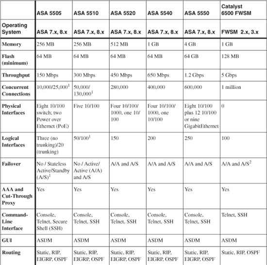
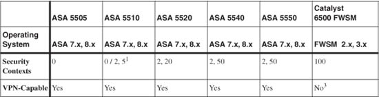
1. Base license/Security Plus license
2. The FWSM supports only LAN-based failover, because it has no physical failover cable connector.
3. The FWSM does not support any IPSec VPN features except for a 3DES tunnel that is used for management purposes.
1-4 Basic Security Policy Guidelines
As you plan your security policies and configure your firewall, you should keep several things in mind. Rather than presenting a long treatise on security policies and how to protect against vulnerabilities and attacks, this small section provides a short list of rules of thumb. If you follow these suggestions, you should be able to configure a firewall to provide the best possible protection.
• Gather and review firewall logs regularly.
After a firewall is configured, you can easily test to see if it is blocking or permitting access to secured resources according to the correct security policies. However, there is no easy way to watch a denial-of-service or worm attack without seeing a record of traffic being permitted or denied.
A firewall can generate a wealth (and a deluge) of logging information. This data should be collected by a Syslog server that is properly sized for the task. You should also review the Syslog data on a regular basis so that you can spot new malicious activity or expose the use of a vulnerable port you forgot to close.
The most important reason to keep firewall logs is to keep an audit trail of network activity. If you experience an attack or a misuse of network resources, you can rely on the Syslog record as evidence.
• Make inbound ACLs very specific.
You should tightly control traffic coming into your secured network from the public or unsecured side. If you offer public access to a corporate web or e-mail server, for example, be sure to permit only those specific protocols and ports. Otherwise, if you leave the inbound access too broad or open, you increase the chances that someone will find a way to exploit an unexpected protocol or service. In addition, best practices suggest that any inbound access should terminate only on hosts that are located on a demilitarized zone (DMZ) firewall interface—not on the inside network.
As for outbound traffic control, the internal (protected) users are usually well-known and trusted. You can leave the outbound access open, but best practices suggest that you configure outbound access lists to prevent hosts on the inside network from participating in worms or attacks aimed at DMZ or outside networks.
You might also use outbound access lists to enforce corporate policies to limit or prohibit certain activity or to control the access of unauthorized services. The firewall can also authenticate outbound users before giving them access and can work with external servers to control web content.
• Protect the DMZ in several directions.
If corporate resources are offered to the public network, it is usually best to place them in a DMZ. This is a small network on a firewall interface that has a medium level of security. Users on the outside or public network are allowed to reach the servers on the DMZ using specific protocols and ports.
Be careful how you configure the security policies on the DMZ interface. Make sure that outside users are allowed access only to the specific protocols needed. Then make sure that machines on the DMZ interface are allowed access to other inside (secured) hosts using only the protocols needed for data transfer.
For example, suppose you have a public web server that offers information using HTTP. That web server populates its web pages by sending SQL requests to other data center servers on the inside network. For the DMZ, you should configure the firewall to allow outside access to the web server using only TCP port 80 (HTTP). In addition, the DMZ server should be allowed to send only SQL packets toward the inside data center, and nothing else. If you leave open access (any protocol or port number) between the DMZ server and the inside, the DMZ can become a “springboard” so that malicious users on the outside can compromise the DMZ server and use it to compromise others on the inside.
• Be overly cautious about ICMP traffic.
ICMP packets are very useful when you need to troubleshoot access or network response time to a host. Ping (ICMP echo) packets are well known for this. However, configuring a firewall to allow open access for the ICMP protocol usually is not wise.
Malicious users on the outside can use ICMP to detect or attack live hosts on a DMZ or inside network. Typically, best practice is to use a firewall to hide as much information as possible about the internal secured network. Outbound pings might be allowed so that your internal users can test to see if a service is alive on the public Internet. Inbound pings (echo requests) should be denied altogether, because you don’t want outside users to know if your internal services are alive. The only exception might be to allow pings to reach your hosts that offer public services, but nothing else.
Best practices suggest that you allow only specific types of ICMP packets to enter your network from the outside. These include echo-reply, unreachable, and time-exceeded ICMP messages. In any event, you should configure ICMP inspection if at all possible, so that the firewall can make a best effort at tracking and controlling ICMP message exchanges.
• Keep all firewall management traffic secured.
You can manage or maintain a firewall in many ways:
— Open a management session using Telnet, SSH, ASDM, or Cisco Security Manager (CSM)
— Copy a new operating system image or configuration file into the firewall
— Collect Syslog information from the firewall
— Poll firewall parameters through SNMP
— Authenticate users through TACACS+ and RADIUS servers
Clearly, any of these methods can drastically change the firewall’s behavior or operation. You should always make every effort to keep all types of management access limited to an inside or secured network. If you open any management access toward the outside, you stand a chance of letting a malicious user manage your firewall for you. At the least, someone might intercept your Syslog or SNMP traffic and learn something important about your internal network.
If you absolutely need some management access from the outside, only do so through a secure means like a virtual private network (VPN) connection or SSH with a strong authentication method. This allows management traffic to be extended only to someone who can verify his or her identity over an encrypted path.
• Periodically review the firewall rules.
Cisco uses a model called the security wheel. The process of providing network security begins with developing a strong corporate security policy. This includes the following tasks:
— Identifying the resources that will be secured
— Identifying the “inside” users and hosts that will need access to other, less-secure network resources
— Identifying corporate services that will be protected but will be accessible from the unsecured networks
— Developing an authentication scheme, if needed, that can identify and grant permission for corporate and outside users
— Developing a plan for auditing the security activities
Actually implementing and refining the policies becomes a continual process of four steps:
a. Secure the network (configure firewalls, routers, intrusion protection systems, and so on)
b. Monitor and respond to malicious activity
c. Test existing security policies and components
d. Manage and improve network security
Further Reading
Refer to the following recommended sources for further technical information about firewall functionality and securing a network:
Cisco’s SAFE Blueprint documents at http://www.cisco.com/go/safe
Cisco ASA: All-in-One Firewall, IPS, and VPN Adaptive Security Appliance by Omar Santos and Jazib Frahim, Cisco Press, ISBN 1-58705-209-1 (978-1-58705-209-5)
Securing Your Business with Cisco ASA and PIX Firewalls by Greg Abelar, Cisco Press, ISBN 1-58705-214-8 (978-1-58705-214-9)
Firewall Fundamentals by Wes Noonan and Ido Dubrawsky, Cisco Press, ISBN 1-58705-221-0 (978-1-58705-221-7)
Network Security Principles and Practices by Saadat Malik, Cisco Press, ISBN 1-58705-025-0 (978-1-58705-025-1)
Designing Network Security, Second Edition by Merike Kaeo, Cisco Press, ISBN 1-58705-117-6 (978-1-58705-117-3)
Cisco Access Control Security: AAA Administration Services by Brandon Carroll, Cisco Press, ISBN 1-58705-124-9 (978-1-58705-124-1)
Network Security Architectures by Sean Convery, Cisco Press, ISBN 1-58705-115-X (978-1-58705-115-9)