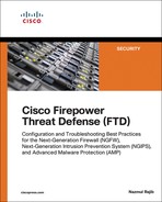
Chapter 6
The Firepower Management Network
After you install the Firepower software, you might wonder how to manage a Firepower Threat Defense (FTD) system. For a smaller network, you can use the browser-based on-box application—the Firepower Device Manager (FDM)—which can manage one FTD device with limited functionalities. However, for a medium- to large-scale network, you must use the Firepower Management Center (FMC). Regardless of how you manage FTD, it is important that you properly design and configure the management network to secure the control traffic.
Firepower System Management Network Essentials
Before you begin the registration process, it is important to ensure that the FMC and FTD can communicate with each other and that they are deployed in appropriate locations in the network. In this section, you will learn about the anatomy of the Firepower management interface and various design scenarios for the Firepower management network.
The FTD Management Interface
The Firepower System uses the management interface to send and receive the control traffic. The implementation of a management interface differs, depending on the hardware platform. This section describes how a management interface works on FTD with two different platforms: Adaptive Security Appliance (ASA) hardware, and Firepower Security Appliance hardware.
![]() On an Adaptive Security Appliance (ASA): On Cisco ASA 5500-X Series hardware, the management interface is located at the rear panel of the ASA hardware, next to the console port (see Figure 6-1).
On an Adaptive Security Appliance (ASA): On Cisco ASA 5500-X Series hardware, the management interface is located at the rear panel of the ASA hardware, next to the console port (see Figure 6-1).

A physical management interface on an ASA comprises two logical interfaces: a logical management interface and a logical diagnostic interface.
FTD uses the logical management interface to complete the registration process with the FMC and to establish a secure tunnel with the FMC. The tunnel, thereafter, is used to set up the FTD, apply policies to the FTD, and transfer events from FTD to the FMC. During the FTD installation process, when you provide an IP address for the FTD management interface, it is actually assigned to the logical management interface.
Figure 6-2 illustrates the relationships between different logical interfaces with different software codes and how they are displayed on the CLI.
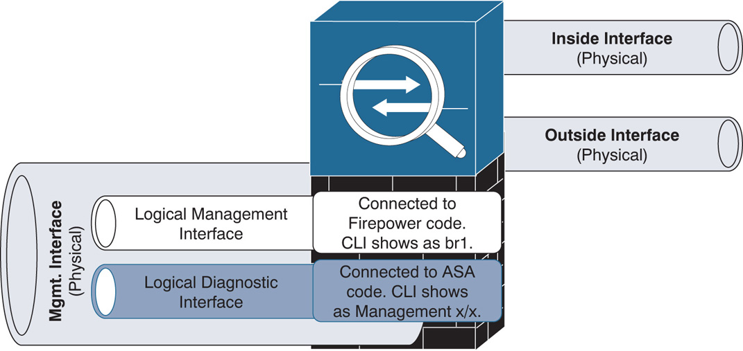
The diagnostic interface, on the other hand, is an optional logical interface. Cisco recommends that you not configure the diagnostic interface with an IP address if there is no router between the management network and the inside network. This also simplifies your network design and reduces configuration overhead.
Note
Each of the FTD data interfaces is required to be on a different network. When a diagnostic interface is configured with an IP address, FTD considers it to be a data interface. Therefore, the diagnostic interface (which must be on the same subnet as the logical management interface, br1) and the inside interface must be on two different subnets. To transfer traffic between two different subnetworks, a router is necessary.
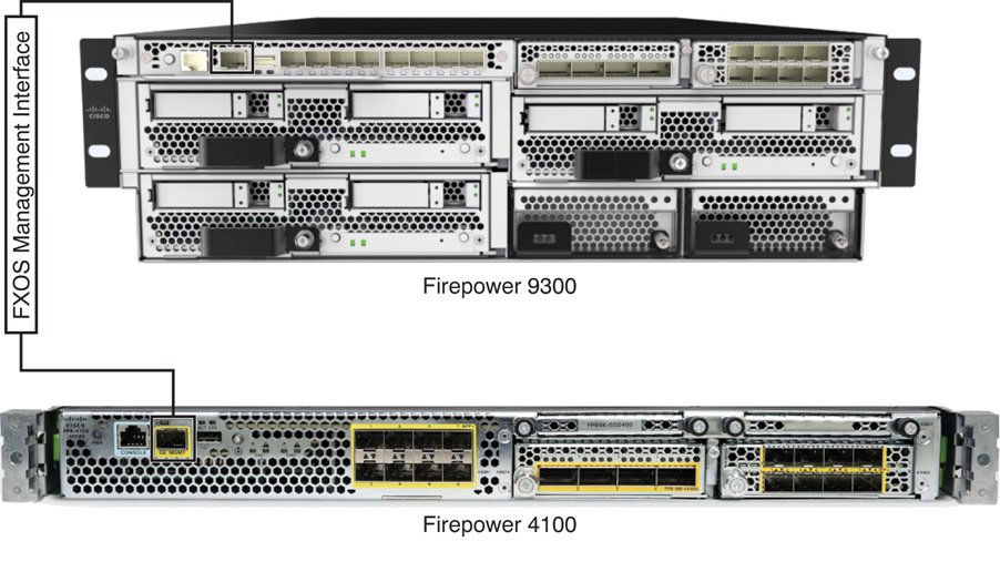
![]() On a Firepower Security Appliance: Each Firepower security appliance has one fixed management interface on the front panel of the chassis. Using this interface, you can administer the Firepower eXtensible Operating System (FXOS). An FTD logical device, however, does not use this interface to communicate with the FMC. For the management communication between FTD and the FMC, you can select any of the remaining Ethernet ports and configure them (with the mgmt. type) by using the Firepower Chassis Manager. (The configuration steps are described later in this chapter, in the section “Configuring a Management Network on a Firepower Security Appliance.”)
On a Firepower Security Appliance: Each Firepower security appliance has one fixed management interface on the front panel of the chassis. Using this interface, you can administer the Firepower eXtensible Operating System (FXOS). An FTD logical device, however, does not use this interface to communicate with the FMC. For the management communication between FTD and the FMC, you can select any of the remaining Ethernet ports and configure them (with the mgmt. type) by using the Firepower Chassis Manager. (The configuration steps are described later in this chapter, in the section “Configuring a Management Network on a Firepower Security Appliance.”)
Figure 6-3 shows the location of the management interface on the Firepower security appliances.
Designing a Firepower Management Network
As long as the management interfaces can communicate with each other, the FMC can manage FTD from any location—either a local area network (LAN) or a wide area network (WAN). Depending on the placement and configuration of the management interfaces, a Firepower management network can be designed various ways.
Figure 6-4 categorizes the possible scenarios for deploying FTD with the FMC:
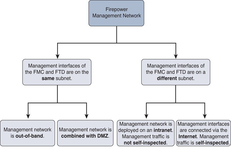
![]() Management interfaces are on the same subnet: You can configure the management interfaces of the FMC and FTD on the same subnetwork and connect them through a Layer 2 switch. The Layer 2 switch for a management network could be completely out-of-band or placed in a network where other servers are currently deployed.
Management interfaces are on the same subnet: You can configure the management interfaces of the FMC and FTD on the same subnetwork and connect them through a Layer 2 switch. The Layer 2 switch for a management network could be completely out-of-band or placed in a network where other servers are currently deployed.
Figure 6-5 shows a deployment in which the management interfaces of the FMC and FTD are configured out-of-band.

![]() Management interfaces are on different subnets: The FMC and FTD can be deployed in two different subnets or branch offices of your company, or even in two different countries. In such a case, you need a router to route the management traffic between Firepower systems.
Management interfaces are on different subnets: The FMC and FTD can be deployed in two different subnets or branch offices of your company, or even in two different countries. In such a case, you need a router to route the management traffic between Firepower systems.
Figure 6-6 shows a design where the management interface of the FMC is connected to two FTD systems that are located at two different networks—one FTD system is in the same DMZ network as the FMC, and the other FTD system is in a separate inside network.
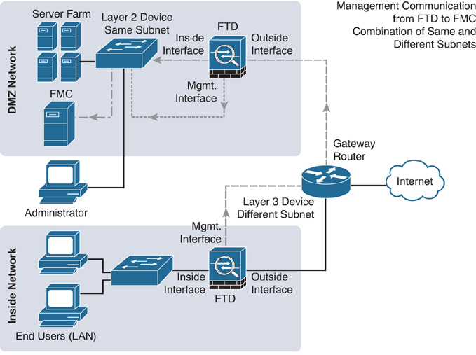
If you do not assign an IP address to the logical diagnostic interface, you can configure the logical management interface and inside interface within the same Layer 2 network and use the inside interface as the gateway for the logical management interface. This allows the FTD to communicate with the FMC over the Internet. However, if you configure the logical diagnostic interface with an IP address anyway (which is not recommended), you end up adding a router between your management network and inside network.
Be mindful when you consider sending Firepower management traffic through the FTD inside interface. If the inside interface flaps, FTD and the FMC can experience intermittent communication failures. If the inside interface goes down, FTD loses its connection to the FMC completely. In this circumstance, a console connection to FTD is critical for investigating the connectivity issue. If console access is not provisioned, you cannot troubleshoot further until physical access to the FTD is possible.
Note
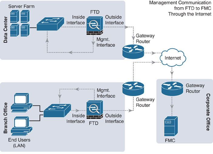
When a Firepower appliance uses a private IP address for its management interface and needs to communicate with another Firepower appliance over the Internet, the private IP address has to be translated to a publicly routable IP address. It is usually performed by a router or firewall using Network Address Translation (NAT). When an intermediate device translates the management IP address of a Firepower appliance, the FMC and FTD must use a unique NAT ID during the registration process.
Figure 6-7 shows FTD systems positioned in various locations in a company and connected through the Internet.
Until an FTD system is registered with the FMC, the web interface does not let you configure the inside and outside interfaces. Hence, you are unable to select the inside interface as a gateway for the management interface until the inside interface is configured and enabled. To address this challenge, follow these steps:
Step 1. Register FTD with the FMC without sending the management traffic through an inside interface. At this point, you can connect the management interfaces of FTD and the FMC directly through a Layer 2 or Layer 3 device. (Refer to Figure 6-5.)
Step 2. After the registration is complete, configure the inside and outside interfaces.
Step 3. When the inside and outside networks are able to communicate with each other, gracefully delete the existing registration between the FMC and FTD.
Step 4. Connect the management interface to the inside network.
Step 5. Reregister the FTD with the FMC. This time, the management traffic should go through the inside network to the FMC in the outside network.
Best Practices for Management Interface Configuration
You can configure a management interface when the Firepower System prompts you to set up the network automatically at the end of the software installation. If you misconfigure at that time or later want to modify the initially configured settings, you can also do that. When you design and configure a Firepower management network, there are a couple best practices you should consider:
![]() You should segregate the management traffic from the data traffic. Keeping the management network out-of-band secures the control-plane traffic in the event that the data network is attacked.
You should segregate the management traffic from the data traffic. Keeping the management network out-of-band secures the control-plane traffic in the event that the data network is attacked.
![]() Although the Firepower System allows you to change the default port for management communication, Cisco strongly recommends that you use the default port TCP 8305.
Although the Firepower System allows you to change the default port for management communication, Cisco strongly recommends that you use the default port TCP 8305.
Configuring a Management Network on FMC Hardware
A brand-new FMC, out of the box, uses 192.168.45.45 as its management IP address. To connect to the FMC through the web interface for the first time, your computer must be able to reach the FMC management network 192.168.45.0/24. Once your computer is able to communicate with the FMC management interface, enter https://192.168.45.45 in your browser to access the GUI.
Note
When you reimage a previously configured FMC, the FMC prompts you to confirm whether you want to keep the prior network settings during the reimaging process. Chapter 4, “Firepower Management Center (FMC) Hardware,” describes the reimaging process in detail.
Configuration Options
You have several options for configuring or modifying the management IP address of the FMC. You can change the IP address during your first login to the FMC web interface or, later, you can use the GUI or CLI to modify the management IP address. These options are detailed in the following sections.
Using the GUI During the First Login
After reimaging, when you log in to the web interface of the FMC for the first time, the initialization page appears. In this page, you can change the default password, network settings, and so on. You can skip the licensing configuration on this page, as you will learn more about licensing in Chapter 7, “Firepower Licensing and Registration.”
Figure 6-8 shows the initial landing page of the FMC. This page appears when you enter the management IP address on a browser for the first time.

After updating the default settings, you need to accept the end user license agreement (EULA) and click the Apply button.
Caution
As soon as you apply a new management IP address, any SSH or HTTPS session to the FMC is disconnected. You have to reconnect to the FMC by using the updated IP address.
Figure 6-9 shows the check box that you must select to accept the EULA and complete the system initialization.

Using the GUI On Demand
Instead of using the GUI during the first login, you can change the management IP address of the FMC whenever you need to. To change the existing network settings of the FMC via the GUI, follow these steps:
Caution
If the FMC is currently managing any FTDs, deregister them from the FMC before you change the management IP address. After you apply the new IP address, reregister them with FMC. Doing this helps you avoid any potential registration or communication issues.
Step 1. Log in to the web interface of the FMC.
Step 2. Go to System > Configuration.
Step 3. Select the Management Interfaces option in the left panel, as shown in Figure 6-10.
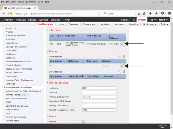
Step 4. In the Configuration page, use the pencil icon to modify the IP addresses. In the Interfaces section, you can enter an IP address for the management interface. Similarly, in the Routes section, you can provide the gateway IP address.
Step 5. When all the necessary network settings are entered, click the Save button at the bottom of the page to save your changes. You are done, and now you should be able to access the FMC by using the new IP address.
Using the Command-Line Interface
To change the network settings on the FMC via the CLI, access the CLI by using Secure Shell (SSH) or the console terminal and run the configure-network command.
Example 6-1 shows the network configuration of a management interface on the FMC. It manually assigns 10.1.1.16/24 for the interface address and 10.1.1.1 for the gateway.
Example 6-1 Configuring Network Settings from the FMC CLI
admin@firepower:~$ sudo configure-network
We trust you have received the usual lecture from the local System
Administrator. It usually boils down to these three things:
#1) Respect the privacy of others.
#2) Think before you type.
#3) With great power comes great responsibility.
Password:
Do you wish to configure IPv4? (y or n) y
Management IP address? [192.168.45.45] 10.1.1.16
Management netmask? [255.255.255.0]
Management default gateway? 10.1.1.1
Management IP address? 10.1.1.16
Management netmask? 255.255.255.0
Management default gateway? 10.1.1.1
Are these settings correct? (y or n) y
Do you wish to configure IPv6? (y or n) n
Updated network configuration.
Updated comms. channel configuration.
Please go to https://10.1.1.16/ or https://[]/ to finish installation.
admin@firepower:~$
Verification and Troubleshooting Tools
Before the registration process, if you experience any connectivity issues between the management interfaces of the FMC and FTD, you can run a couple of command-line tools to verify the network connectivity between your Firepower systems.
First, run the ping test from the CLI of the FMC to the management interface of your FTD device.
Example 6-2 shows a successful ping test from the FMC to 10.1.1.2—the IP address of the management interface. The ping command on the FMC requires root privilege, so you need to run sudo with the ping command.
Example 6-2 Successful Ping Test Between the FMC and FTD
admin@FMC:~$ sudo ping 10.1.1.2
Password:
PING 10.1.1.2 (10.1.1.2) 56(84) bytes of data.
64 bytes from 10.1.1.2: icmp_req=1 ttl=64 time=0.615 ms
64 bytes from 10.1.1.2: icmp_req=2 ttl=64 time=0.419 ms
64 bytes from 10.1.1.2: icmp_req=3 ttl=64 time=0.536 ms
64 bytes from 10.1.1.2: icmp_req=4 ttl=64 time=0.613 ms
^C
--- 10.1.1.2 ping statistics ---
4 packets transmitted, 4 received, 0% packet loss, time 2999ms
rtt min/avg/max/mdev = 0.419/0.545/0.615/0.084 ms
admin@FMC:~$
If the ping test from the FMC to FTD is unsuccessful, check whether the FMC can ping the gateway. Example 6-3 confirms the IP address of the gateway, 10.1.1.1, for eth0—the management interface of the FMC.
Example 6-3 Verifying the Routing Table
admin@FMC:~$ route -n
Kernel IP routing table
Destination Gateway Genmask Flags Metric Ref Use Iface
0.0.0.0 10.1.1.1 0.0.0.0 UG 0 0 0 eth0
10.1.1.0 0.0.0.0 255.255.255.0 U 0 0 0 eth0
admin@FMC:~$
If the FMC can successfully ping the gateway but fails to ping FTD, there must be a routing issue between the FMC and FTD. You can run the traceroute tool on the Firepower System to investigate this issue further, or you can check the configuration on any intermediate routers. The syntax to run the traceroute command on an FMC is as follows:
admin@FMC:~$ sudo traceroute IP_Address_of_FTD
If the connectivity between the FMC and the gateway fails, there is no reason for the FMC to connect to FTD successfully. You should see if the interface is up and connected with a cable. Also, you should make sure the IP address and subnet mask are configured properly. Run the ifconfig command to verify the settings and status.
Example 6-4 shows the assignment of IP address 10.1.1.16 and subnet mask 255.255.255.0. The status of the management interface, eth0, is up. This output also confirms whether the packets are dropped or have errors.
Example 6-4 Verifying Interface Status and IP Address Assignment
admin@FMC:~$ ifconfig
eth0 Link encap:Ethernet HWaddr 00:0C:29:ED:37:B1
inet addr:10.1.1.16 Bcast:10.1.1.255 Mask:255.255.255.0
inet6 addr: fe80::20c:29ff:feed:37b1/64 Scope:Link
UP BROADCAST RUNNING MULTICAST MTU:1500 Metric:1
RX packets:2190 errors:0 dropped:0 overruns:0 frame:0
TX packets:197 errors:0 dropped:0 overruns:0 carrier:0
collisions:0 txqueuelen:1000
RX bytes:150210 (146.6 Kb) TX bytes:25196 (24.6 Kb)
lo Link encap:Local Loopback
inet addr:127.0.0.1 Mask:255.255.255.0
inet6 addr: ::1/128 Scope:Host
UP LOOPBACK RUNNING MTU:65536 Metric:1
RX packets:9789370 errors:0 dropped:0 overruns:0 frame:0
TX packets:9789370 errors:0 dropped:0 overruns:0 carrier:0
collisions:0 txqueuelen:0
RX bytes:2482195842 (2367.2 Mb) TX bytes:2482195842 (2367.2 Mb)
admin@FMC:~$
Configuring a Management Network on ASA Hardware
FTD does not offer a GUI when you want to manage it from the FMC. Therefore, to configure or reconfigure the management interface for FTD, you need to access the CLI.
Configuration
Once you access the CLI, you can run the configure network command to configure all kinds of basic network settings, such as DHCP, manual, IPv4, IPv6, and so on.
To obtain an IP address from the DHCP server, run the following command:
> configure network ipv4 dhcp
To assign an IP address manually, use the following syntax:
> configure network ipv4 manual IP_Address Subnet_Mask Gateway_Address
Note
The configure network ipv4 command changes the IP address of the logical management interface, br1. It does not assign or make any changes on the logical diagnostic interface.
Example 6-5 shows the command to configure a static IP address 10.1.1.2/24 and a gateway IP address 10.1.1.1 for the FTD management interface br1.
Example 6-5 Configuring an IPv4 Address on the FTD Management Interface
> configure network ipv4 manual 10.1.1.2 255.255.255.0 10.1.1.1
Setting IPv4 network configuration.
Network settings changed.
>
Verification and Troubleshooting Tools
Like the FMC, FTD provides various tools to test network settings and connectivity; however, the command syntax is different for FTD. The following examples show some useful FTD commands.
Example 6-6 shows the network settings and the status of the logical management interface br1. The output proves the assignment of port 8305 for transferring management traffic and events. The IP address and MAC address of the logical management interface (br1) are 10.1.1.2 and A4:6C:2A:E4:6B:BE, respectively.
Example 6-6 Verifying the Status of the Logical Management Interface br1
> show network
===============[ System Information ]===============
Hostname : firepower
Management port : 8305
IPv4 Default route
Gateway : 10.1.1.1
======================[ br1 ]=======================
State : Enabled
Channels : Management & Events
Mode : Non-Autonegotiation
MDI/MDIX : Auto/MDIX
MTU : 1500
MAC Address : A4:6C:2A:E4:6B:BE
----------------------[ IPv4 ]----------------------
Configuration : Manual
Address : 10.1.1.2
Netmask : 255.255.255.0
Broadcast : 10.1.1.255
----------------------[ IPv6 ]----------------------
Configuration : Disabled
===============[ Proxy Information ]================
State : Disabled
Authentication : Disabled
>
Did you notice that the command output shown in Example 6-6 does not show the status of the logical diagnostic interface, Management x/x? To determine the status of the diagnostic interface and any other interfaces, run the show interface ip brief command at the FTD CLI.
Example 6-7 shows an overview of all the interfaces. The output confirms that there is no IP address assigned to the logical diagnostic interface Management1/1.
Example 6-7 A Brief Overview of the FTD Interfaces
> show interface ip brief
Interface IP-Address OK? Method Status Protocol
Virtual0 127.1.0.1 YES unset up up
GigabitEthernet1/1 unassigned YES unset administratively down down
GigabitEthernet1/2 unassigned YES unset administratively down down
GigabitEthernet1/3 unassigned YES unset administratively down down
GigabitEthernet1/4 unassigned YES unset administratively down down
GigabitEthernet1/5 unassigned YES unset administratively down down
GigabitEthernet1/6 unassigned YES unset administratively down down
GigabitEthernet1/7 unassigned YES unset administratively down down
GigabitEthernet1/8 unassigned YES unset administratively down down
Internal-Control1/1 127.0.1.1 YES unset up up
Internal-Data1/1 unassigned YES unset up up
Internal-Data1/2 unassigned YES unset down down
Internal-Data1/3 unassigned YES unset up up
Internal-Data1/4 169.254.1.1 YES unset up up
Management1/1 unassigned YES unset up up
>
Tip
The diagnostic interface Management1/1 is an optional logical interface. Cisco recommends that you not configure the diagnostic interface with an IP address if there is no router between the management network and the inside network. This also simplifies your network design and reduces configuration overhead and any potential mistakes.
In your output, if you do not see 1/1 with the management interface name, it is okay. The numbering scheme of a management interface depends on the hardware platform you are running. Table 6-1 shows the management interface numbering for different hardware platforms.
Table 6-1 Management Interface Numbering
Hardware Platform |
Interface Numbering |
ASA 5506, 5508, 5516 |
Management1/1 |
ASA 5512, 5515, 5525, 5545, 5555 |
Management0/0 |
Firepower 4100, 9300 |
Management0 |
Example 6-8 shows that FTD is running a successful ping test to its manager, using the IP address of the FMC management interface, 10.1.1.16.
Example 6-8 Running a Ping Test Appropriately
> ping system 10.1.1.16
PING 10.1.1.16 (10.1.1.16) 56(84) bytes of data.
64 bytes from 10.1.1.16: icmp_seq=1 ttl=64 time=0.593 ms
64 bytes from 10.1.1.16: icmp_seq=2 ttl=64 time=0.654 ms
64 bytes from 10.1.1.16: icmp_seq=3 ttl=64 time=0.663 ms
64 bytes from 10.1.1.16: icmp_seq=4 ttl=64 time=0.699 ms
^C
--- 10.1.1.16 ping statistics ---
4 packets transmitted, 4 received, 0% packet loss, time 2999ms
rtt min/avg/max/mdev = 0.593/0.652/0.699/0.042 ms
>
Example 6-9 shows that FTD fails to ping the management IP address of the FMC when the ping request is sent from the diagnostic CLI instead of the default CLI. This happens because the diagnostic interface has no IP address. (Use the command as shown in Example 6-8 when you want to run a proper ping test from FTD.)
Example 6-9 Ping Test Showing No Success Although the Connection Is Established
> system support diagnostic-cli
Attaching to ASA console ... Press 'Ctrl+a then d' to detach.
Type help or '?' for a list of available commands.
firepower> enable
Password:
firepower# ping 10.1.1.16
Type escape sequence to abort.
Sending 5, 100-byte ICMP Echos to 10.1.1.16, timeout is 2 seconds:
No route to host 10.1.1.16
Success rate is 0 percent (0/1)
firepower#
Configuring a Management Network on a Firepower Security Appliance
To manage FTD, you have to configure one of the interfaces from the network modules for management communication. This section describes the steps to configure and verify the status of a management interface for both FXOS and FTD on a Firepower security appliance.
Configuring the FXOS Management Interface
The embedded management interface that is located on the front panel of a Firepower security appliance is used to manage FXOS. You can configure that interface by using the FXOS CLI.
To configure the network settings for a management interface that provides administrative access to the FXOS software, run the set out-of-band command at the CLI. After any changes, you must apply the configuration in order for it to take effect.
Example 6-10 shows how to assign an IP address and gateway to the FXOS management interface.
Example 6-10 Setting Up an IP Address and Gateway for the FXOS Management Interface
Firepower-9300# scope fabric-interconnect a
Firepower-9300 /fabric-interconnect # set out-of-band ip 10.1.1.28 netmask
255.255.255.0 gw 10.1.1.1
Warning: When committed, this change may disconnect the current CLI session
Firepower-9300 /fabric-interconnect* #
! The above command does not take an effect until you run the following command and
commit the changes.
Firepower-9300 /fabric-interconnect* # commit-buffer
Firepower-9300 /fabric-interconnect #
! If you misconfigured or do not want to apply a recent change, you could discard it
from the buffer as well. To discard, run the following command.
Firepower-9300 /fabric-interconnect* # discard-buffer
Firepower-9300 /fabric-interconnect #
Verification of the FXOS Management Interface Configuration
The command syntax on FXOS is different from the syntax on an ASA or FTD software. In FXOS, when you run a particular command, you must enter an appropriate module or scope. The following are some testing tools that are run on the FMC or ASA hardware earlier in this chapter. Now you can see these tests performed once again, but this time with different command syntax that works only on FXOS.
Example 6-11 shows the command to connect to the local-mgmt module and how to run a ping test from there.
Example 6-11 Successful Ping Test from FXOS to the FMC Management Interface
Firepower-9300# connect local-mgmt
Firepower-9300(local-mgmt)# ping 10.1.1.1
PING 10.1.1.1 (10.1.1.1) from 10.1.1.28 eth0: 56(84) bytes of data.
64 bytes from 10.1.1.1: icmp_seq=1 ttl=255 time=0.298 ms
64 bytes from 10.1.1.1: icmp_seq=2 ttl=255 time=0.412 ms
64 bytes from 10.1.1.1: icmp_seq=3 ttl=255 time=0.392 ms
64 bytes from 10.1.1.1: icmp_seq=4 ttl=255 time=0.390 ms
^C
--- 10.1.1.1 ping statistics ---
4 packets transmitted, 4 received, 0% packet loss, time 3007ms
rtt min/avg/max/mdev = 0.298/0.373/0.412/0.044 ms
Firepower-9300(local-mgmt)#
Example 6-12 shows the command to verify the network settings and the status of the FXOS management interface.
Example 6-12 Status of a Management Interface
Firepower-9300# connect local-mgmt
Firepower-9300(local-mgmt)# show mgmt-port
eth0 Link encap:Ethernet HWaddr B0:AA:77:2F:84:71
inet addr:10.1.1.28 Bcast:10.122.144.255 Mask:255.255.255.0
inet6 addr: fe80::b2aa:77ff:fe2f:8471/64 Scope:Link
UP BROADCAST RUNNING MULTICAST MTU:1500 Metric:1
RX packets:4980815 errors:0 dropped:0 overruns:0 frame:0
TX packets:2680187 errors:0 dropped:0 overruns:0 carrier:0
collisions:0 txqueuelen:1000
RX bytes:1124575588 (1.0 GiB) TX bytes:1921268851 (1.7 GiB)
Firepower-9300(local-mgmt)#
Example 6-13 shows the command to determine the IP address of the gateway for the FXOS management interface.
Example 6-13 Default Gateway for the FXOS Management Interface
Firepower-9300# show fabric-interconnect
Fabric Interconnect:
ID OOB IP Addr OOB Gateway OOB Netmask OOB IPv6 Address OOB IPv6 Gateway Prefix Operability
-- ----------- ----------- ----------- ---------------- ---------------- ------ -----------
A 10.1.1.28 10.1.1.1 255.255.255.0 :: :: 64 Operable
Firepower-9300#
Configuring the FTD Management Interface
You cannot select the embedded management interface as the FTD management interface. This section describes how to set up a management interface for an FTD logical device.
To configure a new physical interface for management communication or to change the administrative state (enable/disable) of a management interface, follow these steps:
Step 1. Go to the Interfaces page of the Firepower Chassis Manager. By default, you should be at the All Interfaces tab.
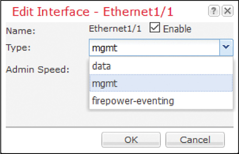
Step 2. Click the pencil icon (at the right-hand side) for the interface you want to modify. The Edit Interface window appears.
Step 3. Using the Type dropdown, select the type of traffic that you want the interface to carry. For example, if you want to select an interface for management communication between an FTD and FMC, select mgmt from the dropdown. Figure 6-11 shows that the Ethernet1/1 interface is enabled and configured for the mgmt (management) type of traffic.
Step 4. Select the Enable check box if you want to enable this interface immediately with the updated settings.
Step 5. Click the OK button to save the changes. The Interfaces page returns, and it now reflects the changes you have made.
Figure 6-12 shows the status of each of the two types of management interfaces—one for FXOS and the other for FTD—after they are configured, administratively enabled, and physically connected.

If you want to modify the management IP address of an already configured FTD or intend to use a different physical management interface for an FTD, follow these steps:
Step 1. On the Firepower Chassis Manager, go to the Logical Devices page. The FTD logical device, if configured, should appear.
Step 2. Click the pencil icon (at the right-hand side) for the FTD logical device you want to modify. An FTD Provisioning page appears.
Step 3. Click the Click to Configure rectangular box. A configuration window appears. Figure 6-13 shows the FTD configuration window. In it, you can modify the settings of an FTD management interface.
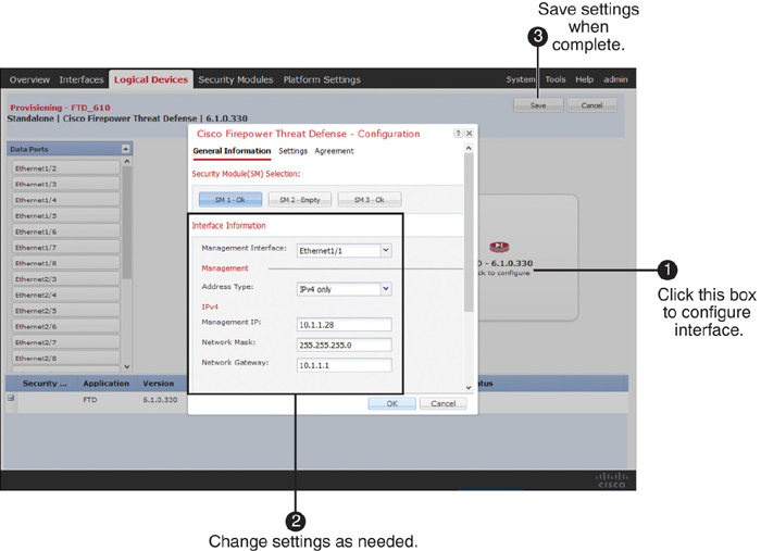
Step 4. When you are done with any modification, click OK, and then click the Save button to apply the changes.
After you change the FTD management IP address and commit changes using the Firepower Chassis Manager, the FTD logical device reinitializes and resets all bootstrap settings.
Verification of the FTD Management Interface Configuration
Example 6-14 shows the interfaces for an FTD logical device. By running the show configuration command within the scope of ssa, you can verify whether the selected physical interfaces are properly mapped with a logical device.
Example 6-14 Mapping Physical Interfaces with an FTD Logical Device
Firepower-9300# scope ssa
Firepower-9300 /ssa # show configuration
scope ssa
enter logical-device FTD_61 ftd 1 standalone
enter external-port-link Ethernet11_ftd Ethernet1/1 ftd
set decorator ""
set description ""
set port-name Ethernet1/1
exit
enter external-port-link Ethernet23_ftd Ethernet2/3 ftd
set decorator ""
set description ""
set port-name Ethernet2/3
exit
enter external-port-link Ethernet24_ftd Ethernet2/4 ftd
set decorator ""
set description ""
set port-name Ethernet2/4
exit
enter mgmt-bootstrap ftd
enter ipv4 1 firepower
set gateway 10.1.1.1
set ip 10.1.1.28 mask 255.255.255.0
exit
exit
set description ""
set res-profile-name ""
exit
.
.
.
<Output Omitted>
Firepower-9300 /ssa #
Example 6-15 shows the administrative and operational status of each of the interfaces on a Firepower security appliance (except the member interfaces of a port channel). The output shows that the FTD management interface (Ethernet1/1) and both data interfaces (Ethernet2/3 and Ethernet2/4) are enabled and up.
Example 6-15 Status of Each Fixed and Modular Interface from the FXOS CLI
Firepower-9300# scope eth-uplink
Firepower-9300 /eth-uplink # scope fabric a
Firepower-9300 /eth-uplink/fabric # show interface
Interface:
Port Name Port Type Admin State Oper State State Reason
--------------- ------------------ ----------- ---------------- ------------
Ethernet1/1 Mgmt Enabled Up
Ethernet1/2 Data Disabled Sfp Not Present Unknown
Ethernet1/3 Data Disabled Sfp Not Present Unknown
Ethernet1/4 Data Disabled Sfp Not Present Unknown
Ethernet1/5 Data Disabled Sfp Not Present Unknown
Ethernet1/6 Data Disabled Sfp Not Present Unknown
Ethernet1/7 Data Disabled Sfp Not Present Unknown
Ethernet1/8 Data Disabled Sfp Not Present Unknown
Ethernet2/3 Data Enabled Up
Ethernet2/4 Data Enabled Up
Ethernet2/5 Data Disabled Sfp Not Present Unknown
Ethernet2/6 Data Disabled Sfp Not Present Unknown
Ethernet2/7 Data Disabled Sfp Not Present Unknown
Ethernet2/8 Data Disabled Sfp Not Present Unknown
Ethernet3/1 Data Disabled Sfp Not Present Unknown
Ethernet3/2 Data Disabled Sfp Not Present Unknown
Ethernet3/3 Data Disabled Sfp Not Present Unknown
Ethernet3/4 Data Disabled Sfp Not Present Unknown
Ethernet3/5 Data Disabled Sfp Not Present Unknown
Ethernet3/6 Data Disabled Sfp Not Present Unknown
Ethernet3/7 Data Disabled Sfp Not Present Unknown
Ethernet3/8 Data Disabled Sfp Not Present Unknown
Firepower-9300 /eth-uplink/fabric #
Example 6-16 shows how to connect to the FTD logical device from the FXOS CLI and then verify the network settings on the FTD logical device.
Example 6-16 Verifying Network Settings That Are Specific to the FTD Application
Firepower-9300# connect module 1 console
Telnet escape character is '~'.
Trying 127.5.1.1...
Connected to 127.5.1.1.
Escape character is '~'.
CISCO Serial Over LAN:
Close Network Connection to Exit
Firepower-module1> connect ftd
Connecting to ftd console... enter exit to return to bootCLI
> show network
===============[ System Information ]===============
Hostname : Firepower-module1
Management port : 8305
IPv4 Default route
Gateway : 10.1.1.1
==================[ management0 ]===================
State : Enabled
Channels : Management & Events
Mode : Non-Autonegotiation
MDI/MDIX : Auto/MDIX
MTU : 9210
MAC Address : B0:AA:77:2F:84:5D
----------------------[ IPv4 ]----------------------
Configuration : Manual
Address : 10.1.1.28
Netmask : 255.255.255.0
Broadcast : 10.1.1.255
----------------------[ IPv6 ]----------------------
Configuration : Disabled
===============[ Proxy Information ]================
State : Disabled
Authentication : Disabled
>
Summary
In this chapter, you have learned the best practices for designing and configuring a management network for the Firepower System. This chapter discusses the tools you can use to verify any communication issues between the management interfaces of the FMC and FTD. Before you begin the registration process, which is described in Chapter 7, you must ensure that the FMC and FTD are successfully connected through your network.
Quiz
1. To run a ping test from FTD to the FMC, which command syntax would be correct?
a. ping IP_Address
b. sudo ping IP_Address
c. ping system IP_Address
d. ping host IP_Address
2. Which port does the Firepower System use for management communication by default?
a. 22
b. 443
c. 8080
d. 8305
3. During FTD software initialization, you have to configure a network. Which interface on an ASA device is assigned with an IP address from that initial configuration?
a. GigabitEthernet0/0
b. Management0/0
c. Management1/1
d. br1
4. Per Cisco recommendation, one of the interfaces on an ASA device should have no IP address configured. Which interface is this?
a. Management0/0
b. Management1/1
c. br1
d. Both a and b
5. To investigate a communication issue between the FMC and FTD, which of the following tools could be used?
a. ifconfig
b. ping
c. traceroute
d. All of the above
6. Which of the following statements is false?
a. Segregation of management traffic improves security policy.
b. The default Firepower management port should not be changed.
c. The logical management interface is labeled Management0/0 on an ASA platform.
d. FTD does not offer any web interface when it is configured for remote management.