Chapter 9
Firepower Deployment in Transparent Mode
FTD Transparent Mode allows you to control your network traffic like a firewall, while the FTD device stays invisible to the hosts in your network. This chapter discusses the configuration of FTD Transparent Mode.
Transparent Mode Essentials
In Transparent Mode, FTD bridges the inside and outside interfaces into a single Layer 2 network and remains transparent to the hosts. When FTD is in Transparent Mode, the FMC does not allow you to assign an IPv4 address to a directly connected interface. As a result, the hosts are unable to communicate with any connected interfaces. Unlike with Routed Mode, you cannot configure the connected interfaces as the default gateway for the hosts.
You can, however, assign an IP address to the Bridge Virtual Interface (BVI) that comes with each bridge group. A bridge group represents a unique Layer 2 network. You can create multiple bridge groups on a single FTD device, but the hosts within different bridge groups cannot communicate with each other without a router. Within a bridge group, both the BVI and the hosts must have IP addresses from the same subnet. FTD uses the IP address of the BVI when it communicates with its hosts.
Figure 9-1 shows how a host finds a router, not an FTD device, as its next hop when you configure FTD in Transparent Mode.

Figure 9-2 shows an example of a real-world deployment of FTD in Transparent Mode. The management interfaces of the FMC and FTD are connected to the end users through the 192.168.1.0/24 subnet. The default gateway for the 192.168.1.0/24 subnet is the gateway router IP address 192.168.1.30/24.

Best Practices for Transparent Mode
Consider the following when you plan to deploy FTD in Transparent Mode:
![]() Changing the firewall mode wipes out any existing FTD configurations. Therefore, before you change the firewall mode from Routed to Transparent or vice versa, take note of your FTD configuration settings for future reference, in case you want to revert the FTD to the initial state. To view the current FTD configuration, run the show running-config command in the CLI.
Changing the firewall mode wipes out any existing FTD configurations. Therefore, before you change the firewall mode from Routed to Transparent or vice versa, take note of your FTD configuration settings for future reference, in case you want to revert the FTD to the initial state. To view the current FTD configuration, run the show running-config command in the CLI.
If you just want to change the firewall mode on an FTD device, performing a backup of your security policy configuration is not necessary because the next-generation security policies are defined and stored on the FMC. Once configured, FMC can deploy the same policies to one or more FTD devices.
![]() Do not use the BVI IP address as the default gateway for the connected hosts. Instead, use any connected router as the default gateway for the hosts in the bridged network.
Do not use the BVI IP address as the default gateway for the connected hosts. Instead, use any connected router as the default gateway for the hosts in the bridged network.
![]() Do not forget to add access rules to allow any necessary network management traffic. By default, FTD in Transparent Mode blocks the DHCP traffic, multicast traffic, and dynamic routing protocol traffic (such as RIP, OSPF, EIGRP, BGP, and so on). If you select Access Control: Block All Traffic as the default action, make sure you have added access rules explicitly to allow any essential traffic. If you are not sure, you can use Intrusion Prevention: Balanced Security and Connectivity as the default action; it allows any unmatched traffic, as long as there are no malicious activities found.
Do not forget to add access rules to allow any necessary network management traffic. By default, FTD in Transparent Mode blocks the DHCP traffic, multicast traffic, and dynamic routing protocol traffic (such as RIP, OSPF, EIGRP, BGP, and so on). If you select Access Control: Block All Traffic as the default action, make sure you have added access rules explicitly to allow any essential traffic. If you are not sure, you can use Intrusion Prevention: Balanced Security and Connectivity as the default action; it allows any unmatched traffic, as long as there are no malicious activities found.
![]() If your ultimate goal is to perform transparent inspection, you can choose the Inline IPS mode instead of the Transparent firewall mode. While both modes allow you to deploy FTD as a bump in the wire, Inline Mode has less configuration overhead than Transparent Mode. In addition, a dedicated IP address for each BVI is not necessary. To learn more, read Chapter 11, “Blocking Traffic Using Inline Interface Mode.”
If your ultimate goal is to perform transparent inspection, you can choose the Inline IPS mode instead of the Transparent firewall mode. While both modes allow you to deploy FTD as a bump in the wire, Inline Mode has less configuration overhead than Transparent Mode. In addition, a dedicated IP address for each BVI is not necessary. To learn more, read Chapter 11, “Blocking Traffic Using Inline Interface Mode.”
Configuring Transparent Mode
During system initialization, FTD provides you an option to choose between Routed Mode and Transparent Mode (see Example 9-1). To set up FTD with Transparent Mode, just type transparent when the system prompts and press Enter.
Example 9-1 Configuring Transparent Firewall Mode During Initialization
<Output Omitted>
.
.
Manage the device locally? (yes/no) [yes]: no
Configure firewall mode? (routed/transparent) [routed]: transparent
Configuring firewall mode ...
.
.
<Output Omitted>
If you selected Transparent Mode during the system initialization, you can skip the next two sections and read the section “Deploying Transparent Mode in a Layer 2 Network.” If you selected Routed Mode, read on.
Fulfilling Prerequisites
You cannot change the firewall mode if FTD is currently registered with the FMC. If you initially configured FTD to Routed Mode and now you want to reconfigure it to Transparent Mode, you must unregister FTD from the FMC. To verify the registration status, run the show managers command at the FTD CLI.
Example 9-2 shows that FTD is currently registered with the FMC with IP address 10.1.1.16.
Example 9-2 Verifying the Registration Status—FTD Is Currently Registered
> show managers
Type : Manager
Host : 10.1.1.16
Registration : Completed
>
If you find that FTD is currently registered with the FMC, unregister it by using the FMC web interface. To delete the registration, go to the Devices > Device Management page and click the delete icon next to the appropriate FTD device (see Figure 9-3).

Example 9-3 shows confirmation that FTD is currently not registered with the FMC.
Example 9-3 Verifying the Registration Status—FTD Is Not Registered
> show managers
No managers configured.
>
Changing the Firewall Mode
If an FTD device is currently not associated with a manager, you can change the firewall deployment mode. To configure an FTD device with Transparent Mode, log in to the FTD CLI and run the configure firewall transparent command (see Example 9-4).
Example 9-4 Configuring Transparent Mode
> configure firewall transparent
This will destroy the current interface configurations, are you sure that you want
to proceed? [y/N] y
The firewall mode was changed successfully.
After configuring FTD with the desired mode, you can determine the status from the CLI, as shown in Example 9-5.
Example 9-5 Verifying Firewall Deployment Mode
> show firewall
Firewall mode: Transparent
>
Alternatively, upon a successful registration, the web interface of the FMC also displays the current firewall deployment mode. You can view it on the Devices > Device management page (see Figure 9-4).

Deploying Transparent Mode in a Layer 2 Network
An FTD device in Transparent Mode can control traffic as a firewall and inspect traffic as an intrusion prevention system while it stays transparent in the network, like a Layer 2 switch. A transparent FTD supports the following deployment scenarios:
![]() You can deploy it in a single Layer 2 network, where all the hosts reside in the same subnet and can communicate without a dynamic routing protocol. This type of deployment works when you configure the physical and virtual interfaces in a bridge group.
You can deploy it in a single Layer 2 network, where all the hosts reside in the same subnet and can communicate without a dynamic routing protocol. This type of deployment works when you configure the physical and virtual interfaces in a bridge group.
![]() You can also deploy an FTD device between the Layer 3 networks, where hosts from different subnets communicate using a routing protocol. By default, when you configure an FTD device in Transparent Mode, it blocks any underlying dynamic routing protocol traffic. Therefore, to allow this traffic, you need to add access rules explicitly.
You can also deploy an FTD device between the Layer 3 networks, where hosts from different subnets communicate using a routing protocol. By default, when you configure an FTD device in Transparent Mode, it blocks any underlying dynamic routing protocol traffic. Therefore, to allow this traffic, you need to add access rules explicitly.
Configuring the Physical and Virtual Interfaces
To configure the interfaces when an FTD device is in Transparent Mode, follow these steps:
Step 1. Navigate to the Devices > Device Management page. A list of the managed devices appears.
Step 2. Click the pencil icon that is next to the FTD device you want to configure. The device editor page appears, showing all the physical interfaces of an FTD device on the Interfaces tab (see Figure 9-5).

Step 3. On the Interfaces tab, click the pencil icons next to GigabitEthernet1/1 and GigabitEthernet1/2 to configure these interfaces for the inside and outside networks. Use the settings shown in Table 9-1 to configure these two interfaces.
Table 9-1 Configuration Settings for GigabitEthernet1/1 and GigabitEthernet1/2
|
GigabitEthernet1/1 |
GigabitEthernet1/2 |
Interface name |
INSIDE_INTERFACE |
OUTSIDE_INTERFACE |
Security zone (optional) |
INSIDE_ZONE |
OUTSIDE_ZONE |
IP address |
In Transparent Mode, an IP address is not required on a data interface. Instead, assign an address to the BVI. |
|
Note
To enable an interface, giving it a name is a requirement; however, configuring a security zone is an optional step.
Figure 9-6 shows the configurations on the GigabitEthernet1/1 interface. Note that there is no option to configure an IPv4 address.

Figure 9-7 shows the configurations on the GigabitEthernet1/2 interface that is connected to the outside network.

Step 4. After you configure both interfaces, click the Save button to save the changes you have made so far (see Figure 9-8). The configuration is now saved on the FMC for future use. The FMC applies the configuration to an FTD device only when you click the Deploy button, which you will do soon.

Step 5. To configure a BVI, on the right side of the Interfaces tab, click the Add Interfaces button. A list of different types of interfaces appears.
Step 6. Select Bridge Group Interface from the list of interfaces (see Figure 9-9). The Add Bridge Group Interface window appears.

Step 7. On the Interfaces tab of the Add Bridge Group Interface window, provide a bridge group ID between 1 and 250 and select the interfaces that are part of the bridged network—in this case GigabitEthernet1/1 and GigabitEthernet1/2, as shown in Figure 9-10.

Step 8. On the IPv4 subtab, configure the address 192.168.1.1 for the BVI (see Figure 9-11). The IP address must be on the same subnet as the hosts and default gateway router, and in this case it is within the same /24 subnet as its hosts.

Step 9. Click OK to exit the Add Bridge Group Interface window. Figure 9-12 confirms the setup of a bridge group BVI1.

Step 10. Click the Save button to save the changes, and then click the Deploy button to apply the changes to the FTD device.
Verifying the Interface Status
After deploying an FTD device by using the FMC web interface, you can verify any configuration settings from the FTD CLI.
Example 9-6 shows the interface configuration of FTD in Transparent Mode. Both of the member interfaces are in bridge group 1 and have no IP addresses. Only BVI1 has an IP address (192.168.1.1/24).
Example 9-6 Interface Configurations on an FTD in Transparent Mode
> show running-config interface
!
interface GigabitEthernet1/1
nameif INSIDE_INTERFACE
cts manual
propagate sgt preserve-untag
policy static sgt disabled trusted
bridge-group 1
security-level 0
!
interface GigabitEthernet1/2
nameif OUTSIDE_INTERFACE
cts manual
propagate sgt preserve-untag
policy static sgt disabled trusted
bridge-group 1
security-level 0
.
.
<Output Omitted for Brevity>
.
.
interface Management1/1
management-only
nameif diagnostic
cts manual
propagate sgt preserve-untag
policy static sgt disabled trusted
security-level 0
!
interface BVI1
ip address 192.168.1.1 255.255.255.0
>
Example 9-7 highlights the status of the interfaces on a Transparent Mode FTD device. Although you do not configure IP addresses for the member interfaces of a bridge group, they use the same IP address as the BVI when you communicate with any connected hosts.
Example 9-7 Interface Status of FTD in Transparent Mode
> show interface ip brief
Interface IP-Address OK? Method Status Protocol
Virtual0 127.1.0.1 YES unset up up
GigabitEthernet1/1 192.168.1.1 YES unset up up
GigabitEthernet1/2 192.168.1.1 YES unset up up
GigabitEthernet1/3 unassigned YES unset administratively down down
GigabitEthernet1/4 unassigned YES unset administratively down down
GigabitEthernet1/5 unassigned YES unset administratively down down
GigabitEthernet1/6 unassigned YES unset administratively down down
GigabitEthernet1/7 unassigned YES unset administratively down down
GigabitEthernet1/8 unassigned YES unset administratively down down
Internal-Control1/1 127.0.1.1 YES unset up up
Internal-Data1/1 unassigned YES unset up up
Internal-Data1/2 unassigned YES unset down down
Internal-Data1/3 unassigned YES unset up up
Internal-Data1/4 169.254.1.1 YES unset up up
Management1/1 unassigned YES unset up up
BVI1 192.168.1.1 YES manual up up
>
Example 9-8 shows the status of the logical management interface br1, which is not displayed in the previous example. FTD uses the IP address of br1 to communicate with the FMC.
Example 9-8 Status of the Logical Management Interface br1
> show network
===============[ System Information ]===============
Hostname : firepower
Management port : 8305
IPv4 Default route
Gateway : 10.1.1.1
======================[ br1 ]=======================
State : Enabled
Channels : Management & Events
Mode : Non-Autonegotiation
MDI/MDIX : Auto/MDIX
MTU : 1500
MAC Address : A4:6C:2A:E4:6B:BE
----------------------[ IPv4 ]----------------------
Configuration : Manual
Address : 10.1.1.2
Netmask : 255.255.255.0
Broadcast : 10.1.1.255
----------------------[ IPv6 ]----------------------
Configuration : Disabled
===============[ Proxy Information ]================
State : Disabled
Authentication : Disabled
>
Verifying Basic Connectivity and Operations
After configuring an FTD device to Transparent Mode, you might want to verify whether the transparent FTD is working. Is it invisible in the network? You can prove this by using Address Resolution Protocol (ARP). When a host computer communicates through an FTD device, the host cannot see the FTD device. Instead, it can see the devices deployed on the other side of the FTD device.
Before testing the functionality, let’s determine the MAC and IP addresses of all the participating interfaces. Figure 9-13 details the Layer 1, Layer 2, and Layer 3 addresses of the network devices in the OSPF area 1 network. Instead of seeing the FTD inside interface, the inside router sees the outside router as its next hop.

Example 9-9 shows the commands that allow you to find the MAC and IP addresses of an interface on an FTD device and a router.
Example 9-9 Determining the MAC and IP Addresses
! On FTD:
> show interface GigabitEthernet1/1 | include address
MAC address a46c.2ae4.6bc0, MTU 1500
IP address 192.168.1.1, subnet mask 255.255.255.0
> show interface GigabitEthernet1/2 | include address
MAC address a46c.2ae4.6bc1, MTU 1500
IP address 192.168.1.1, subnet mask 255.255.255.0
! On Router:
Inside-Router# show interfaces GigabitEthernet2 | include address
Hardware is CSR vNIC, address is 000c.2943.7b76 (bia 000c.2943.7b76)
Internet address is 192.168.1.20/24
Outside-Router## show interfaces GigabitEthernet3 | include address
Hardware is CSR vNIC, address is 000c.2965.d399 (bia 000c.2965.d399)
Internet address is 192.168.1.30/24
If you configured the interfaces according to the instructions in the previous section, you should be able to successfully ping from the inside router to the outside router.
Example 9-10 shows a successful ping test from the inside router to the outside router through the FTD. The dropping of the first packet is an expected behavior. It happens because the ARP table is empty at the beginning.
Example 9-10 Sending a Successful Ping Request from Inside to Outside
Inside-Router# ping 192.168.1.30
Type escape sequence to abort.
Sending 5, 100-byte ICMP Echos to 192.168.1.30, timeout is 2 seconds:
.!!!!
Success rate is 80 percent (4/5), round-trip min/avg/max = 5/5/6 ms
Inside-Router#
The ping test by the inside router (shown in Example 9-10) does not prove whether the ping replies come from the outside router or from the BVI of the FTD. You can determine this by enabling debugging on FTD for ICMP traffic, like this:
> debug icmp trace
debug icmp trace enabled at level 1
>
Once again, you can send the ping requests to the IP address of the outside router 192.168.1.30 from the inside router. The requests go through the FTD device as in the previous example. However, this time, the FTD device shows a log for the through traffic. There are two lines for each ping request—one for sending a request and one for receiving a reply:
ICMP echo request from INSIDE_INTERFACE:192.168.1.20 to OUTSIDE_
INTERFACE:192.168.1.30 ID=8 seq=1 len=72
ICMP echo reply from OUTSIDE_INTERFACE:192.168.1.30 to INSIDE_
INTERFACE:192.168.1.20 ID=8 seq=1 len=72
Now check the ARP table on the inside router to view the mapping of IP addresses with the inside interface. Compare the entries in the table with the MAC addresses that you found in the command output shown in Example 9-9.
Example 9-11 displays the mapping of the MAC addresses with the IP addresses. Besides the MAC address of its own interface (000c.2943.7b76), the ARP table of the inside router shows the MAC address of its next hop—the outside router (000c.2965.d399), not the FTD (a46c.2ae4.6bc0), which is transparent in the network.
Example 9-11 Inside Router ARP Table—After Pinging from the Inside Router to the Outside Router
Inside-Router# show arp
Protocol Address Age (min) Hardware Addr Type Interface
Internet 192.168.1.20 - 000c.2943.7b76 ARPA GigabitEthernet2
Internet 192.168.1.30 2 000c.2965.d399 ARPA GigabitEthernet2
Inside-Router#
If you send a ping request from the FTD device, FTD uses its BVI IP address to send that request. In that case, the ARP table on the router shows the MAC address of the FTD interface that communicates with the router.
Example 9-12 demonstrates that when you ping from FTD to the inside router, it uses the BVI address 192.168.1.1 as its IP address. Remember that in Transparent Mode, you do not configure any IPv4 address on the FTD physical interface.
Example 9-12 BVI IP Address Used When Traffic Originates from the FTD Itself
> debug icmp trace
debug icmp trace enabled at level 1
> ping 192.168.1.20
ICMP echo request from 192.168.1.1 to 192.168.1.20 ID=52779 seq=30330 len=72
ICMP echo reply from 192.168.1.20 to 192.168.1.1 ID=52779 seq=30330 len=72
.
<Output Omitted for Brevity>
.
! To disable the debug of ICMP traffic:
> no debug icmp trace
debug icmp trace disabled.
>
! Alternatively, to disable all of the running debug processes:
> undebug all
>
Example 9-13 shows a new entry in the ARP table after you send the ping requests to the inside router from the FTD device. It now displays the MAC address of the GigabitEthernet1/1 interface (a46c.2ae4.6bc0) in FTD.
Example 9-13 Inside Router ARP Table—After Pinging from FTD to the Inside Router
Inside-Router# show arp
Protocol Address Age (min) Hardware Addr Type Interface
Internet 192.168.1.1 1 a46c.2ae4.6bc0 ARPA GigabitEthernet2
Internet 192.168.1.20 - 000c.2943.7b76 ARPA GigabitEthernet2
Internet 192.168.1.30 5 000c.2965.d399 ARPA GigabitEthernet2
Inside-Router#
Deploying an FTD Device Between Layer 3 Networks
After configuring the physical and virtual interfaces, you can communicate with any hosts, through an FTD device, within the same subnet. However, if you want to communicate with hosts that are in different subnets, a routing protocol is necessary.
When you configure a dynamic routing protocol across the network, FTD blocks the underlying routing traffic until you allow it in an access control policy. You can choose one of following options:
![]() Select a nonblocking policy as the default action.
Select a nonblocking policy as the default action.
![]() Add a custom access rule to allow desired traffic.
Add a custom access rule to allow desired traffic.
Figure 9-14 shows an FTD device deployed between an inside router and an outside router. Both routers use loopback interfaces to simulate a host and the Internet. The loopback and routing interfaces are on different subnets, and all of them are included in OSPF area 1.

Selecting the Default Action
The default action in an access control policy determines how an FTD device handles traffic when there is no matching access rule. To define the default action, you can either go to the Policies > Access Control page to create a new policy or you can edit an existing policy. Figure 9-15 shows the options to create a new access control policy and to modify an existing one.

When you are on the policy editor page, select the desired policy from the Default Action dropdown. You can select one of the system-provided policies that does not block traffic or a policy that you have created (if any). If you are not sure about selecting a policy, you can select the Intrusion Prevention: Balanced Security and Connectivity policy, which allows any unmatched traffic to go through an FTD device after being inspected for malicious activities.
Figure 9-16 shows a list of system-provided policies that you can select for default action. Once you select a policy, save the changes and deploy it on your FTD.

Adding an Access Rule
If you select the Access Control: Block All Traffic policy as the default action, traffic is blocked when it does not match with any custom access rules. Only the traffic that exclusively matches a rule is allowed through the FTD device.
If you create an access rule to allow a particular routing protocol, such as OSPF, and select the Access Control: Block All Traffic policy as the default action, the FTD device allows only OSPF management traffic. Any other data traffic, however, is dropped due to the default blocking action. In this scenario, two routers can build an OSPF neighbor relationship through an FTD device, but you are unable to ping the inside router from the outside router and vice versa. Similarly, you cannot use Secure Shell (SSH) to access a router from the other router even though the neighbor relation is established. To allow any additional traffic, you need to add the related protocols in the access rule and select the Allow action.
In the following configuration example, you will see how to create two access rules—one for the routing traffic (OSPF) and one for the data traffic (SSH).
To create an access rule for OSPF traffic, follow these steps:
Step 1. Go to the Policies > Access Control page. Click the New Policy button to create a new policy, or click on the pencil icon to edit an existing policy. The policy editor page appears.
Step 2. To create a new access rule, on the policy editor page, click the Add Rule button (see Figure 9-17). The Add Rule window appears.

Step 3. Give a name to this particular access rule, select the Enabled check box, and set the action to Allow. Figure 9-18 shows how to enable a new access rule called Routing Access with the rule action set to Allow.

Routers exchange keepalives to determine the states of the neighbors. If an FTD device deployed between two routers inspects a very high volume of traffic, it may delay the traverse of keepalive packets even if you add an access rule to allow them. As a result, a router may take a longer time to call its neighbor down, which makes any reachability issues worse.
Tip
The Firepower System offers two unique rule actions—Trust and Fastpath—that can expedite the traverse of management traffic. In an access rule, you can set the action to Trust to let the OSPF traffic go through the FTD device without any further inspection. However, the more optimal method for bypassing an inspection is to add a prefilter rule for the OSPF protocol and set the action for it to Fastpath. To learn about the details of both options, see Chapter 14, “Bypassing Inspection and Trusting Traffic.”
Step 4. Go to the Ports tab and navigate to the Protocol dropdown that is under the Selected Destination Ports field.
Step 5. Select the OSPF/OSPFIGP protocol and click the Add button next to the protocol dropdown. The selected protocol should be listed under the Selected Destination Ports box. Figure 9-19 shows the sequence for adding an access rule called Routing Access to allow the OSPF protocol.

Step 6. Click the Add button to return to the policy editor page, where you can see the rule you just created.
Creating an Access Rule for SSH
You can create a rule to allow data traffic through the SSH protocol. The following steps show how to allow destination port 22—the default port for SSH:
Step 1. Click the Add Rule button once again. In the Add Rule window, provide a name for the rule, select the Enabled check box, and set the Allow action.
Step 2. In the Available Ports section, select SSH and click the Add to Destination button. The SSH protocol appears under the Selected Destination Ports box. Figure 9-20 shows the steps to create an access rule named Shell Access to allow the SSH traffic via port 22.

Note
Step 2 allows SSH traffic that is destined for port 22, which is also the default port for the SSH protocol. If you want to allow any SSH application traffic, regardless of its destination port, you need to create a rule by using the Applications tab. To learn more about the Firepower application control, read Chapter 19, “Discovering Network Applications and Controlling Application Traffic.”
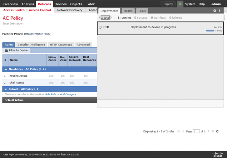
Step 3. Click the Add button to return to the policy editor page and select the Access Control: Block All Traffic policy as the Default Action. Figure 9-21 shows that two rules—Routing Access and Shell Access—are added. As the default action, Access Control: Block All Traffic is added.

Step 4. Add more access rules as necessary. For now, in this configuration example, just create the above two access rules, save the policy, and deploy the new configuration on the FTD. Figure 9-22 shows that the new access control policy is being deployed. It may take several minutes to complete the deployment.
Verifying Access Control Lists
When traffic is not blocked or allowed according to the configurations on the FMC, you can use the FTD CLI to verify whether the desired access rules are applied. You can run the show access-list command to view the custom access rules you created, as well as any implicit or system-generated rules that are applied to the FTD.
Example 9-14 shows the system-generated access rules when an access control policy with no custom rule is applied. The last rule on line 10, permit ip any any, is applied implicitly when you select a nonblocking default action. The following example uses the Balanced Security and Connectivity policy as the default action.
Example 9-14 No Custom Rule with the Balanced Security and Connectivity Default Policy
> show access-list
access-list cached ACL log flows: total 0, denied 0 (deny-flow-max 4096)
alert-interval 300
access-list CSM_FW_ACL_; 6 elements; name hash: 0x4a69e3f3
access-list CSM_FW_ACL_ line 1 remark rule-id 9998: PREFILTER POLICY: Default Tunnel
and Priority Policy
access-list CSM_FW_ACL_ line 2 remark rule-id 9998: RULE: DEFAULT TUNNEL ACTION RULE
access-list CSM_FW_ACL_ line 3 advanced permit ipinip any any rule-id 9998
(hitcnt=0) 0xf5b597d6
access-list CSM_FW_ACL_ line 4 advanced permit 41 any any rule-id 9998 (hitcnt=0)
0x06095aba
access-list CSM_FW_ACL_ line 5 advanced permit gre any any rule-id 9998 (hitcnt=0)
0x52c7a066
access-list CSM_FW_ACL_ line 6 advanced permit udp any eq 3544 any range 1025 65535
rule-id 9998 (hitcnt=0) 0x46d7839e
access-list CSM_FW_ACL_ line 7 advanced permit udp any range 1025 65535 any eq 3544
rule-id 9998 (hitcnt=0) 0xaf1d5aa5
access-list CSM_FW_ACL_ line 8 remark rule-id 268434432: ACCESS POLICY: AC Policy -
Default/1
access-list CSM_FW_ACL_ line 9 remark rule-id 268434432: L4 RULE: DEFAULT ACTION
RULE
access-list CSM_FW_ACL_ line 10 advanced permit ip any any rule-id 268434432
(hitcnt=3281) 0xa1d3780e
>
Example 9-15 shows two custom access rules on lines 10 and 13, along with other system-generated rules, that are created on the FMC and applied to FTD. These rules allow FTD to permit OSPF and SSH traffic. The last rule on line 16, deny ip any any, is applied implicitly when you select Access Control: Block All Traffic as the default action.
Example 9-15 Two Custom Rules with Block All Traffic as the Default Policy
> show access-list
access-list cached ACL log flows: total 0, denied 0 (deny-flow-max 4096)
alert-interval 300
access-list CSM_FW_ACL_; 8 elements; name hash: 0x4a69e3f3
access-list CSM_FW_ACL_ line 1 remark rule-id 9998: PREFILTER POLICY: Default Tunnel
and Priority Policy
access-list CSM_FW_ACL_ line 2 remark rule-id 9998: RULE: DEFAULT TUNNEL ACTION RULE
access-list CSM_FW_ACL_ line 3 advanced permit ipinip any any rule-id 9998
(hitcnt=0) 0xf5b597d6
access-list CSM_FW_ACL_ line 4 advanced permit 41 any any rule-id 9998 (hitcnt=0)
0x06095aba
access-list CSM_FW_ACL_ line 5 advanced permit gre any any rule-id 9998 (hitcnt=0)
0x52c7a066
access-list CSM_FW_ACL_ line 6 advanced permit udp any eq 3544 any range 1025 65535
rule-id 9998 (hitcnt=0) 0x46d7839e
access-list CSM_FW_ACL_ line 7 advanced permit udp any range 1025 65535 any eq 3544
rule-id 9998 (hitcnt=0) 0xaf1d5aa5
access-list CSM_FW_ACL_ line 8 remark rule-id 268437504: ACCESS POLICY: AC Policy -
Mandatory/1
access-list CSM_FW_ACL_ line 9 remark rule-id 268437504: L7 RULE: Routing Access
access-list CSM_FW_ACL_ line 10 advanced permit ospf any any rule-id 268437504
(hitcnt=4) 0x385cc1f6
access-list CSM_FW_ACL_ line 11 remark rule-id 268437505: ACCESS POLICY: AC Policy -
Mandatory/2
access-list CSM_FW_ACL_ line 12 remark rule-id 268437505: L7 RULE: Shell Access
access-list CSM_FW_ACL_ line 13 advanced permit tcp any any object-group SSH rule-id
268437505 (hitcnt=8) 0x030eea01
access-list CSM_FW_ACL_ line 13 advanced permit tcp any any eq ssh rule-id
268437505 (hitcnt=8) 0xf8ca4a86
access-list CSM_FW_ACL_ line 14 remark rule-id 268434432: ACCESS POLICY: AC Policy -
Default/1
access-list CSM_FW_ACL_ line 15 remark rule-id 268434432: L4 RULE: DEFAULT ACTION
RULE
access-list CSM_FW_ACL_ line 16 advanced deny ip any any rule-id 268434432 event-log
flow-start (hitcnt=826) 0x97aa021a
>
If you set the default action to block all traffic and do not permit the OSPF traffic through an access list, the neighbor relationship breaks. When a neighbor goes down, FTD triggers an alert on the CLI similar to the following:
Jan 31 04:00:51.434: %OSPF-5-ADJCHG: Process 1, Nbr 3.3.3.3 on GigabitEthernet2
from FULL to DOWN, Neighbor Down: Dead timer expired
Summary
This chapter discusses the Transparent firewall mode and how to configure the physical and virtual interfaces. Furthermore, you have learned about various command-line tools that enable you to investigate any potential configuration issues.
Quiz
1. Which of the following statements is true about deployment?
a. You can replace a Layer 2 switch with a transparent FTD device; there is no difference between them.
b. Switching between Transparent Mode and Routed Mode requires a restart.
c. You can use the FMC to configure an FTD device from Routed Mode to Transparent Mode.
d. Changing the firewall deployment mode erases any existing configuration.
2. Which of the following statements is true about an IP address?
a. You should use the IP address of a BVI as the default gateway for the hosts in a bridged network.
b. The IP address of a BVI should be on a different subnet than any hosts in the bridge group.
c. The BVI’s IP address is used as the source IP address for packets that originate from an FTD device.
d. You can configure an IPv4 address on any physical interface.
3. Which of the following statements is true when you select the Access Control: Block All Traffic policy as the default action?
a. It overrides any “allow” access rules deployed on an FTD device.
b. It blocks the traffic when the intrusion prevention system of an FTD device finds no malicious activities.
c. This policy is equivalent to the deny tcp any any access rule.
d. It blocks any traffic that does not match an existing access rule.
4. Which of the following commands displays the access rule entries?
a. show access-control
b. show access-control-rule
c. show access-list
d. show access-list-config