Chapter 8
Firepower Deployment in Routed Mode
You can deploy a Firepower Threat Defense (FTD) device as a default gateway for your network so that the hosts can communicate with the FTD device in order to connect to any different subnet or the Internet. You can also deploy an FTD device transparently, so that it becomes invisible to the hosts in your network. In short, you can deploy an FTD device in two ways—Routed Mode and Transparent Mode. This chapter describes the processes involved in deploying an FTD device in routed mode. Chapter 9, “Firepower Deployment in Transparent Mode,” covers Transparent Mode.
Routed Mode Essentials
In Routed Mode, FTD performs like a Layer 3 hop. Each interface on an FTD device connects to a different subnet. If configured to do so, an FTD device can act as a default gateway for any particular subnet and can route traffic between different subnets.
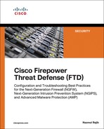
Figure 8-1 shows how a host interacts with an FTD device as its next Layer 3 hop. In Routed Mode, each FTD interface connects to a unique subnet.
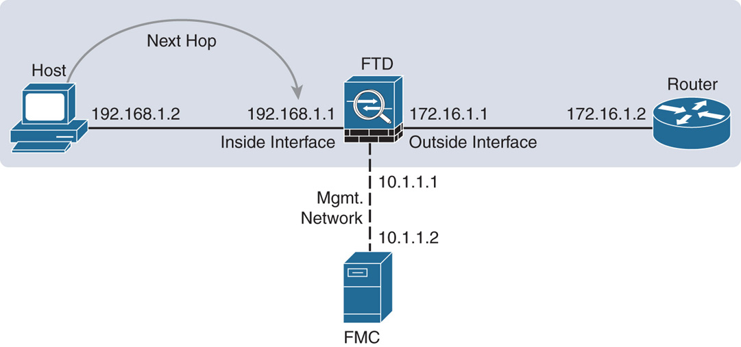
Figure 8-2 shows the default gateways on each segment when an FTD device is deployed in a typical real-world network. The end users on a LAN use the FTD physical interface as their gateway. An FTD device can also use its inside interface as the default gateway for its management communication.

Best Practices for Routed Mode Configuration
If you want to deploy FTD in Routed Mode, consider the following suggestions:
![]() Cisco recommends that you not configure the diagnostic interface with an IP address. This simplifies the network design and reduces configuration overhead. When a diagnostic interface is configured with an IP address, FTD considers it a data interface. Each data interface on an FTD device is required to be on a different network. Therefore, the diagnostic interface (which must be on the same subnet as the logical management interface, br1) and the inside interface must be on two different subnets. To transfer traffic between two different subnetworks, a router is required.
Cisco recommends that you not configure the diagnostic interface with an IP address. This simplifies the network design and reduces configuration overhead. When a diagnostic interface is configured with an IP address, FTD considers it a data interface. Each data interface on an FTD device is required to be on a different network. Therefore, the diagnostic interface (which must be on the same subnet as the logical management interface, br1) and the inside interface must be on two different subnets. To transfer traffic between two different subnetworks, a router is required.
![]() Changing the firewall mode wipes out any existing FTD configurations. Therefore, before you change the firewall mode from Transparent to Routed or vice versa, take note of your FTD configuration settings for future reference, in case you want to revert the FTD to the initial state. To view the current FTD configuration, run the show running-config command in the CLI.
Changing the firewall mode wipes out any existing FTD configurations. Therefore, before you change the firewall mode from Transparent to Routed or vice versa, take note of your FTD configuration settings for future reference, in case you want to revert the FTD to the initial state. To view the current FTD configuration, run the show running-config command in the CLI.
If you just want to change the firewall mode on an FTD device, performing a backup of your security policy configuration is not necessary because the next-generation security policies are defined and stored on the FMC. After you configure the policies, FMC allows you to deploy the same policies to one or more FTD devices.
Configuring Routed Mode
Do you remember the last part of the FTD installation and initialization process? During the initialization, FTD prompts to confirm the firewall mode, and you can select between Routed Mode and Transparent Mode (see Example 8-1).
Example 8-1 Configuring the Firewall Mode During the Initialization
<Output Omitted>
.
.
Manage the device locally? (yes/no) [yes]: no
Configure firewall mode? (routed/transparent) [routed]:
Configuring firewall mode ...
Update policy deployment information
- add device configuration
- add network discovery
- add system policy
.
.
<Output Omitted>
If you selected Routed Mode during the system initialization, you can skip the next two sections and read the section “Configuring the Routed Interfaces.” If you selected Transparent Mode, read on.
Fulfilling Prerequisites
If you selected Transparent Mode during the system initialization and now you want to reconfigure FTD to Routed Mode, you must unregister FTD from the FMC. You cannot change the firewall mode when a manager is configured. To verify whether FTD is currently registered with the FMC, run the show managers command at the FTD CLI.
Example 8-2 shows that FTD is currently registered with the FMC with IP address 10.1.1.16.
Example 8-2 Verifying the Registration Status—FTD Is Currently Registered
> show managers
Type : Manager
Host : 10.1.1.16
Registration : Completed
>
If you find that FTD is currently registered with the FMC, you can unregister it from the FMC web interface. To delete registration, go to the Devices > Device Management page and click the delete icon next to FTD (see Figure 8-3).

Example 8-3 shows confirmation that FTD is currently not registered with the FMC.
Example 8-3 Verifying the Registration Status—FTD Is Not Registered
> show managers
No managers configured.
>
Configuring the Firewall Mode
If FTD is currently not registered with the FMC, you can change the firewall deployment mode. To configure an FTD with Routed Mode, log in to the FTD CLI and run the configure firewall routed command (see Example 8-4).
Example 8-4 Configuring the Routed Mode
> configure firewall routed
This will destroy the current interface configurations, are you sure that you want to proceed? [y/N] y
The firewall mode was changed successfully.
After configuring FTD with the desired mode, you can determine the status from the CLI. Example 8-5 shows confirmation that FTD is configured to Routed Mode.
Example 8-5 Verifying the Firewall Deployment Mode
> show firewall
Firewall mode: Router
>
Alternatively, upon a successful registration, the web interface of the FMC also displays the current firewall deployment mode. You can view it at the Devices > Device Management page. Figure 8-4 indicates that FTD is configured in Routed Mode.

Configuring the Routed Interface
In FTD, you can configure a data interface with a static IP address. FTD can also work as a DHCP client and obtain an IP address from a DHCP server. Furthermore, you can enable DHCP service on FTD to enable it to assign an IP address dynamically to its host.
Configuring an Interface with a Static IP Address
To configure a routed interface with a static IP address, follow these steps:
Step 1. Navigate to the Devices > Device Management page. A list of the managed devices appears.
Step 2. Click the pencil icon that is next to the FTD device you want to configure. The device editor page appears, showing all the physical interfaces of an FTD device on the Interfaces tab (see Figure 8-5).

Step 3. On the Interfaces tab, click the pencil icons next to GigabitEthernet1/1 and GigabitEthernet1/2 to configure these interfaces for the inside and outside networks. Use the settings shown in Table 8-1 to configure these two interfaces.
Table 8-1 Configuration Settings for GigabitEthernet1/1 and GigabitEthernet1/2
|
GigabitEthernet1/1 |
GigabitEthernet1/2 |
Interface name |
INSIDE_INTERFACE |
OUTSIDE_INTERFACE |
Security zone (optional) |
INSIDE_ZONE |
OUTSIDE_ZONE |
IP address |
192.168.1.1/24 |
172.16.1.1/24 |
Note
To enable an interface, giving it a name is a requirement. However, configuring a security zone is an optional step.
Figure 8-6 shows these interfaces, which are each connected to two different subnets.

Figure 8-7 shows the configurations on the GigabitEthernet1/1 interface that can act as the default gateway for the inside network.

Figure 8-8 shows the configurations on the GigabitEthernet1/2 interface that is connected to the outside network.

Step 4. After you configure both interfaces, click the Save button to save the configurations.
Step 5. Click the Deploy button to apply the configurations to FTD (see Figure 8-9).

DHCP Services
FTD can function as a DHCP server as well as a DHCP client. For example, if you deploy an FTD device between your inside and outside networks, the device can obtain an IP address dynamically for its outside interface from an ISP router. Simultaneously, FTD can act as a DHCP server and provide IPv4 addresses dynamically to the hosts it inspects.
Note
Configuring FTD as a DHCP server is an optional choice; it does not influence the deep packet inspection capability. The DHCP implementation on the Firepower software has limitations. It depends on various factors, such as the Internet Protocol version (IPv4 versus IPv6), FTD firewall mode (Routed versus Transparent), and the type of services (DHCP server versus DHCP relay). Read the official Cisco Firepower publications to find any version-specific limitations and enhancements.
Figure 8-10 illustrates two scenarios: The inside network obtains an IP address from the DHCP service running on FTD, while the outside interface of the FTD device gets an IP address from a service provider.

FTD as a DHCP Server
The following steps describe how to enable the DHCP service on an FTD device and allow the inside interface to provide IPv4 addresses to its connected host computers:
Step 1. Go to the Devices > Device Management page and click the pencil icon to edit the FTD configuration.
Step 2. Assign the static IP address 192.168.1.1 on GigabitEthernet1/1—the inside interface of FTD—as shown in Figure 8-11. Your end users (DHCP clients) will be using this IP address as their default gateway.
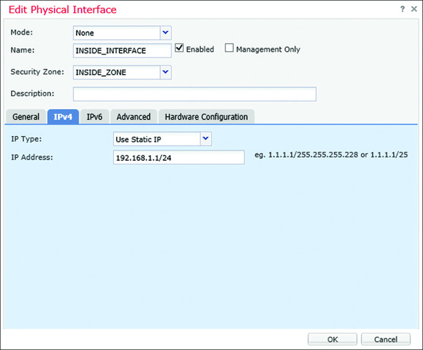
Step 3. In the device editor page, go to the DHCP tab. By default, the DHCP Server page appears.
Step 4. Click the Add button in the Server tab (located in the bottom part of the DHCP Server page). The Add Server window appears.
Step 5. In the Add Server window, select the inside interface from the dropdown list as it will be offering IP addresses to the inside network.
Step 6. Create an address pool for the DHCP server. Remember that the addresses in the pool must be within the same subnet as the connected interface. For example, if you assign 192.168.1.1/24 to the inside interface, the DHCP address pool should be between 192.168.1.2 and 192.168.1.254.
Figure 8-12 shows that a DHCP server is enabled on the FTD inside interface with the address pool 192.168.1.2 to 192.168.1.10.
Step 7. Select the Enable DHCP Server check box to enable the service and click OK. You are returned to the device editor page.
Step 8. Optionally, through the DHCP service, transfer any DNS-related information to your DHCP clients. The DHCP Server page allows you to enter domain name and DNS addresses manually. Alternatively, you can select the Auto-Configuration check box to let FTD obtain any DNS information automatically from a DHCP client connected to a predefined interface.
Step 9. Click the Save button to save the configuration, and then click the Deploy button to apply the changes.
FTD as a DHCP Client
If you connect the outside interface of FTD with an Internet service provider (ISP), FTD can accept any dynamic IP address assigned by an ISP. To accept a DHCP offer from an external server, perform the following tasks in FTD:
Step 1. Go to the Devices > Device Management page and click the pencil icon next to the FTD device that you want to configure.
Step 2. Edit the interface that is connected to an external DHCP server—in this example, the outside interface GigabitEthernet1/2.
Step 3. In the Edit Physical Interface window, select the check box to enable the interface. Specify a name and a security zone for this interface. (Skip this step if you configured these items previously during the static IP address configuration.)
Figure 8-13 shows the configurations on the outside interface that will be able to obtain an IP address from a DHCP server.

Step 4. On the IPv4 tab, choose Use DHCP from the dropdown list and select the Obtain Default Route Using DHCP check box.
Step 5. Click OK to exit the Edit Physical Interface window.
Step 6. Click the Save button to save the configuration, and then click the Deploy button to apply the changes.
The outside interface now should see an offer from an external DHCP server.
Verification and Troubleshooting Tools
Once the ingress and egress interfaces are successfully configured and enabled, you should be able to ping from the inside network to the outside network and vice versa. While you run ICMP traffic, you can view the transaction of packets going through FTD by using the debug command.
Example 8-6 shows ICMP requests and replies exchanged between two computers located in inside and outside networks.
Example 8-6 Debugging ICMP Traffic in FTD
> debug icmp trace
debug icmp trace enabled at level 1
>
ICMP echo request from INSIDE_INTERFACE:192.168.1.2 to OUTSIDE_INTERFACE:172.16.1.100 ID=4101 seq=1 len=56
ICMP echo reply from OUTSIDE_INTERFACE:172.16.1.100 to INSIDE_INTERFACE:192.168.1.2 ID=4101 seq=1 len=56
ICMP echo request from INSIDE_INTERFACE:192.168.1.2 to OUTSIDE_INTERFACE:172.16.1.100 ID=4101 seq=2 len=56
ICMP echo reply from OUTSIDE_INTERFACE:172.16.1.100 to INSIDE_INTERFACE:192.168.1.2 ID=4101 seq=2 len=56
.
.
<Output Omitted>
> undebug all
>
If the ping test fails, you need to determine the status of the interfaces. You can run a couple commands in FTD to verify the configurations you applied from the FMC to the FTD. As shown in the following sections, command outputs are slightly different depending on the configuration method (static versus dynamic).
Verifying the Interface Configuration
The following commands are useful for verifying the interface configuration and status:
![]() show ip
show ip
![]() show interface ip brief
show interface ip brief
![]() show interface interface_ID
show interface interface_ID
![]() show running-config interface
show running-config interface
Example 8-7 shows output of the show ip command. You can view the mapping between the interface, logical name, and IP address in this output. You cannot, however, view the current status in the output.
Example 8-7 Output of the show ip Command
> show ip
System IP Addresses:
Interface Name IP address Subnet mask Method
GigabitEthernet1/1 INSIDE_INTERFACE 192.168.1.1 255.255.255.0 manual
GigabitEthernet1/2 OUTSIDE_INTERFACE 172.16.1.1 255.255.255.0 manual
Current IP Addresses:
Interface Name IP address Subnet mask Method
GigabitEthernet1/1 INSIDE_INTERFACE 192.168.1.1 255.255.255.0 manual
GigabitEthernet1/2 OUTSIDE_INTERFACE 172.16.1.1 255.255.255.0 manual
>
Example 8-8 confirms that both the GigabitEthernet1/1 and GigabitEthernet1/2 interfaces are up and configured manually (using static IP addresses). The show interface ip brief command provides an overview, including the current status, of each of the interfaces.
Example 8-8 Overview of the Interface Status
> show interface ip brief
Interface IP-Address OK? Method Status Protocol
Virtual0 127.1.0.1 YES unset up up
GigabitEthernet1/1 192.168.1.1 YES manual up up
GigabitEthernet1/2 172.16.1.1 YES manual up up
GigabitEthernet1/3 unassigned YES unset administratively down down
GigabitEthernet1/4 unassigned YES unset administratively down down
GigabitEthernet1/5 unassigned YES unset administratively down down
GigabitEthernet1/6 unassigned YES unset administratively down down
GigabitEthernet1/7 unassigned YES unset administratively down down
GigabitEthernet1/8 unassigned YES unset administratively down down
Internal-Control1/1 127.0.1.1 YES unset up up
Internal-Data1/1 unassigned YES unset up up
Internal-Data1/2 unassigned YES unset down down
Internal-Data1/3 unassigned YES unset up up
Internal-Data1/4 169.254.1.1 YES unset up up
Management1/1 unassigned YES unset up up
>
Example 8-9 shows detailed statistics of the GigabitEthernet1/1 interface. By using the show interface interface_ID command, you can determine any errors and drops that may have occurred on an interface.
Example 8-9 Detailed Statistics of Packets in the Interface Level
> show interface GigabitEthernet 1/1
Interface GigabitEthernet1/1 "INSIDE_INTERFACE", is up, line protocol is up
Hardware is Accelerator rev01, BW 1000 Mbps, DLY 10 usec
Auto-Duplex(Full-duplex), Auto-Speed(1000 Mbps)
Input flow control is unsupported, output flow control is off
MAC address a46c.2ae4.6bc0, MTU 1500
IP address 192.168.1.1, subnet mask 255.255.255.0
3541 packets input, 379530 bytes, 0 no buffer
Received 54 broadcasts, 0 runts, 0 giants
0 input errors, 0 CRC, 0 frame, 0 overrun, 0 ignored, 0 abort
0 pause input, 0 resume input
0 L2 decode drops
2875 packets output, 292832 bytes, 0 underruns
0 pause output, 0 resume output
0 output errors, 0 collisions, 0 interface resets
0 late collisions, 0 deferred
0 input reset drops, 0 output reset drops
input queue (blocks free curr/low): hardware (938/895)
output queue (blocks free curr/low): hardware (1023/1022)
Traffic Statistics for "INSIDE_INTERFACE":
3534 packets input, 315149 bytes
2875 packets output, 240884 bytes
658 packets dropped
1 minute input rate 2 pkts/sec, 168 bytes/sec
1 minute output rate 2 pkts/sec, 168 bytes/sec
1 minute drop rate, 0 pkts/sec
5 minute input rate 2 pkts/sec, 168 bytes/sec
5 minute output rate 2 pkts/sec, 168 bytes/sec
5 minute drop rate, 0 pkts/sec
>
Example 8-10 displays the interface configurations from the CLI. You can find all the settings you configured on the FMC and applied to FTD. The system, however, adds some commands automatically when you apply the final configurations.
Example 8-10 Running Configurations of GigabitEthernet1/1 and GigabitEthernet1/2
> show running-config interface
!
interface GigabitEthernet1/1
nameif INSIDE_INTERFACE
cts manual
propagate sgt preserve-untag
policy static sgt disabled trusted
security-level 0
ip address 192.168.1.1 255.255.255.0
!
interface GigabitEthernet1/2
nameif OUTSIDE_INTERFACE
cts manual
propagate sgt preserve-untag
policy static sgt disabled trusted
security-level 0
ip address 172.16.1.1 255.255.255.0
!
.
.
<Output Omitted for Brevity>
>
Verifying DHCP Settings
If an FTD device does not offer an IP address to its DHCP clients, or if the FTD device cannot obtain an IP address from any external DHCP server, you can verify the configurations and debug any DHCP packets to and from the DHCP server. Let’s take a look.
Example 8-11 confirms that GigabitEthernet1/2, connected to the outside network, can obtain the IP address 172.16.1.104 from a DHCP server.
Example 8-11 Status of an Outside Interface—Configured with a Dynamic IP Address
> show interface ip brief
Interface IP-Address OK? Method Status Protocol
Virtual0 127.1.0.1 YES unset up up
GigabitEthernet1/1 192.168.1.1 YES manual up up
GigabitEthernet1/2 172.16.1.104 YES DHCP up up
GigabitEthernet1/3 unassigned YES unset administratively down down
GigabitEthernet1/4 unassigned YES unset administratively down down
GigabitEthernet1/5 unassigned YES unset administratively down down
GigabitEthernet1/6 unassigned YES unset administratively down down
GigabitEthernet1/7 unassigned YES unset administratively down down
GigabitEthernet1/8 unassigned YES unset administratively down down
Internal-Control1/1 127.0.1.1 YES unset up up
Internal-Data1/1 unassigned YES unset up up
Internal-Data1/2 unassigned YES unset down down
Internal-Data1/3 unassigned YES unset up up
Internal-Data1/4 169.254.1.1 YES unset up up
Management1/1 unassigned YES unset up up
>
Example 8-12 shows the differences between the configurations of two interfaces: The inside interface GigabitEthernet1/1 is configured with the static IP address 192.168.1.1/24, whereas the outside interface GigabitEthernet1/2 is configured to obtain an address from a DHCP server.
Example 8-12 The Difference Between Static and DHCP Configurations in the CLI
> show running-config interface
!
interface GigabitEthernet1/1
nameif INSIDE_INTERFACE
cts manual
propagate sgt preserve-untag
policy static sgt disabled trusted
security-level 0
ip address 192.168.1.1 255.255.255.0
!
interface GigabitEthernet1/2
nameif OUTSIDE_INTERFACE
cts manual
propagate sgt preserve-untag
policy static sgt disabled trusted
security-level 0
ip address dhcp setroute
!
.
.
<Output Omitted for Brevity>
>
Example 8-13 proves that FTD has dynamically assigned the IP address 192.168.1.2 to a host with MAC address C4:2C:03:3C:98:A8. This IP address is the first address from the DHCP address pool 192.168.1.2 to 192.168.1.10.
Example 8-13 Verifying the IP Address Assignment from a DHCP Address Pool
> show dhcpd binding
IP address Client Identifier Lease expiration Type
192.168.1.2 c42c.033c.98a8 3580 seconds Automatic
>
If you do not see any DHCP binding, you can debug the DHCP packets on the FTD device.
Example 8-14 demonstrates the process of a DHCP server assigning an IP address. In the debug output, you can analyze the four major stages of the DHCP protocol—Discovery, Offer, Request, and Acknowledgement (DORA).
Example 8-14 Exchanging DHCP Packets Between FTD and a DHCP Server
> debug dhcpd packet
debug dhcpd packet enabled at level 1
>
DHCPD/RA: Server msg received, fip=ANY, fport=0 on INSIDE_INTERFACE interface
DHCPD: DHCPDISCOVER received from client c42c.033c.98a8 on interface INSIDE_INTERFACE.
DHCPD: send ping pkt to 192.168.1.2
DHCPD: ping got no response for ip: 192.168.1.2
DHCPD: Add binding 192.168.1.2 to radix tree
DHCPD/RA: Binding successfully added to hash table
DHCPD: Sending DHCPOFFER to client c42c.033c.98a8 (192.168.1.2).
DHCPD: Total # of raw options copied to outgoing DHCP message is 0.
DHCPD/RA: creating ARP entry (192.168.1.2, c42c.033c.98a8).
DHCPD: unicasting BOOTREPLY to client c42c.033c.98a8(192.168.1.2).
DHCPD/RA: Server msg received, fip=ANY, fport=0 on INSIDE_INTERFACE interface
DHCPD: DHCPREQUEST received from client c42c.033c.98a8.
DHCPD: Extracting client address from the message
DHCPD: State = DHCPS_REBOOTING
DHCPD: State = DHCPS_REQUESTING
DHCPD: Client c42c.033c.98a8 specified it's address 192.168.1.2
DHCPD: Client is on the correct network
DHCPD: Client accepted our offer
DHCPD: Client and server agree on address 192.168.1.2
DHCPD: Renewing client c42c.033c.98a8 lease
DHCPD: Client lease can be renewed
DHCPD: Sending DHCPACK to client c42c.033c.98a8 (192.168.1.2).
DHCPD: Total # of raw options copied to outgoing DHCP message is 0.
DHCPD/RA: creating ARP entry (192.168.1.2, c42c.033c.98a8).
DHCPD: unicasting BOOTREPLY to client c42c.033c.98a8(192.168.1.2).
>
Summary
In this chapter, you have learned about the widely deployed firewall mode Routed Mode. This chapter describes the steps involved in configuring routed interfaces with static IP addresses as well as dynamic IP addresses. In addition, this chapter discusses various command-line tools you can use to determine any potential interface-related issues.
Quiz
1. Which of the following commands is used to debug and analyze ping requests?
a. debug icmp
b. debug ip icmp
c. debug icmp trace
d. debug icmp reply
2. Which of the following commands is used to configure FTD from Transparent Mode to Routed Mode?
a. configure routed
b. configure firewall routed
c. configure firepower routed
d. configure transparent disable
3. Which of the following statements is true?
a. FTD in Transparent Mode cannot be configured by the FMC.
b. You can change the firewall deployment mode by using the FMC.
c. You cannot change the firewall mode until you unregister FTD from the FMC.
d. When you change the firewall mode, FTD saves the running configurations.
4. Which of the following commands allows you to determine any interface-related issues?
a. show interface ip brief
b. show interface interface_ID
c. show running-config interface