CHAPTER 3
Storage Networking
In this chapter, you will learn about
• Storage types and technologies
• Storage access protocols
• Storage provisioning
• Storage protection
Storage is the foundation of a successful infrastructure. The traditional method of storing data is changing with the emergence of cloud storage. Storage is the instrument that is used to record and play back the bits and bytes that the compute resources process to provide their functions for delivering cloud services and applications.
Cloud storage is being leveraged for a wide range of enterprise functions, from end-user computing to enterprise storage and backup. Furthermore, cloud storage is a platform for explosive growth in organizational data because it is highly available and almost infinitely scalable. Understanding the advantages and disadvantages of storage types and technologies is a key concept for IT and cloud professionals because it will be your responsibility to help the organization understand the risks and the benefits of moving to cloud storage.
Storage Types and Technologies
Just as there are many different environments in which computers are used, there are many types of storage to accommodate each of those environment’s needs. Some storage types are designed to meet primary organizational storage concerns such as cost, performance, reliability, and data security. Figure 3-1 displays a graphical comparison of the three storage types—DAS, SAN, and NAS—which we explore in more detail directly. A fourth type is object storage.
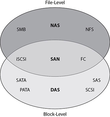
Figure 3-1 Three major storage types: DAS, SAN, and NAS
In addition to the four storage types, this section covers two storage technologies. These technologies—deduplication and compression—improve storage efficiencies by removing unnecessarily redundant data.
Direct Attached Storage
Direct attached storage (DAS) is one or more drives connected to a machine as additional block-level storage. Some storage protocols used to access these storage devices are eSATA, USB, FC, SCSI, and SAS. USB and eSATA are most frequently utilized by desktops and laptops to connect to DAS, while companies typically connect DAS to servers using FC, SCSI, or SAS.
DAS is typically the least expensive storage option available for online storage (as opposed to offline storage such as a tape). As its name suggests, this type of storage is directly attached to the host computer that utilizes it and does not have to traverse a network to be accessed by that host. Direct attached storage is made available only to that local computer and cannot be used as shared storage. Shared storage in this context refers to storage that is made available to multiple machines at the block level. A machine can share out storage that was provided to it by DAS.

EXAM TIP Direct attached storage (DAS) cannot provide shared storage to multiple hosts.
Storage Area Network
A storage area network (SAN) is a high-performance option employed by many data centers as a high-end storage solution with data security capabilities and a very high price tag to go along with it. A SAN is a storage device that resides on its own network and provides block-level access to computers that are attached to it.
The disks that are part of a SAN are combined into RAID groups for redundancy and higher performance. These RAID groups are then carved into subdivisions called logical unit numbers (LUNs) that provide block-level access to specified computers. LUNs can be interacted with just like a logical drive.
SANs are capable of highly complex configurations, allowing administrators to divide storage resources and access permissions granularly and with very high-performance capabilities. However, SAN maintenance and operations can be complicated, often requiring specialized skill sets and knowledge of proprietary technology (because each SAN solution is vendor-specific). The role of SANs is mission-critical, so there is little, if any, margin for error. Many storage administrators go to specialized training for their specific SAN solution, and they spend much of their time in the workplace, giving SANs constant monitoring and attention. These administrative burdens add to the cost of deploying a SAN solution.
SANs can also provide shared storage or access to the same data at the same time by multiple computers. This is critical for enabling high availability (HA) in data center environments that employ virtualization solutions that require access to the same virtual machine files from multiple hosts. Shared storage allows hosts to perform migrations of virtual machines without any downtime, as discussed in more detail in Chapter 5.
Computers require a special adapter to communicate with a SAN, much like they need a network interface card (NIC) to access their data networks. The network that a SAN utilizes is referred to as a fabric and can be composed of fiber-optic cables, Ethernet adapters, or specialized SCSI cables.
A host bus adapter (HBA) is the most common device used to connect a machine to a SAN. An HBA is usually a PCI add-on card that can be inserted into a free slot in a host and then connected either to the SAN disk array directly or, as is more often the case, to a SAN switch. Virtual machines can use a virtual HBA, which emulates a physical HBA and allocates portions of the physical HBA’s bandwidth to virtual machines. Storage data is transferred from the disk array over the SAN to the host via the HBA, which prepares it for processing by the host’s compute resources.
Two other adapters may be used to connect to a storage network. A converged network adapter (CNA) can be used in lieu of an HBA. CNAs are computer expansion cards that can be used as an HBA or a NIC. NetApp has a proprietary adapter called universal target adapter (UTA). UTA has ports for one or more Ethernet or Fibre Channel transceivers and can support Ethernet transceivers up to 10 Gbps and Fibre Channel transceivers at native Fibre Channel speeds.
In addition to SANs, organizations can use a virtual SAN (VSAN), which can consolidate separate physical SAN fabrics into a single larger fabric, allowing for easier management while maintaining security. A VSAN allows identical Fibre Channel IDs to be used at the same time within different VSANs. VSANs allow for user-specified IDs that are used to identify the VSAN. VSANs can also span data centers using VXLANs, discussed more in Chapter 4, or with encapsulation over routable network protocols.
HBAs usually can significantly increase performance by offloading the processing required for the host to consume the storage data without utilizing its processor cycles. This means that an HBA enables greater efficiency for its host by allowing its processor to focus on running the functions of its operating system (OS) and applications instead of on storage I/O.
Network Attached Storage
Network attached storage (NAS) offers an alternative to storage area networks for providing network-based shared storage options. NAS devices utilize TCP/IP networks for sending and receiving storage traffic in addition to data traffic. NAS provides file-level data storage that can be connected to and accessed from a TCP/IP network. Because NAS utilizes TCP/IP networks instead of a separate SAN fabric, many IT organizations can utilize existing infrastructure components to support both their data and storage networks. This use of common infrastructure can greatly cut costs while providing similar shared storage capabilities. Expenses are reduced for a couple of reasons:
• Data networking infrastructure costs significantly less than storage networking infrastructure.
• Shared configurations between data and storage networking infrastructure enable administrators to support both without additional training or specialized skill sets.
One way to differentiate NAS from a SAN is that NAS appears to the client operating system as a file server, whereas a SAN appears to the client operating system as a disk (typically a LUN) that is visible in disk management utilities. This allows NAS to use Universal Naming Convention addressable storage. Network attached storage leverages protocols such as file-sharing protocols like SMB/CIFS and NFS.
NAS also differs from SAN in that NAS natively allows for concurrent access to shares. However, there are some functions that can only be performed on block storage such as booting from SAN storage or loading applications from SAN storage. SAN connections usually offer much higher throughput to storage for high-performance needs.
EXAM TIP A storage area network (SAN) provides much better performance than network attached storage (NAS).
NAS uses file-sharing protocols to make shares available to users across a network. NAS systems typically support both the Common Internet File System (CIFS)/Server Message Block (SMB) for Windows and the Network File System (NFS) for Linux. Many NAS devices also support uploading and downloading files to it via FTP or SSL/TLS-enabled FTP, such as FTPS and SFTP.
Network File System
NFS is a protocol used for network file sharing. It is mainly used on Unix and Linux systems and suffers from very little overhead because of its use of the stateless User Datagram Protocol (UDP) transport protocol. Many NAS operating systems run some version of Linux because there are no licensing costs with it, and NAS vendors can customize the software for their needs. This allows those NAS systems to support NFS out of the box.
Since NFS is a stateless protocol, it does not retain some information on the communication session that CIFS would, such as the current working directory or open files. Each set of requests and responses in NFS is independent. This requires that each response contain all the necessary information to process the request rather than relying on the server to track current network operations. The advantage of such a stateless protocol is that the NAS does not need to retain this information, nor does it need to clean up such information when transactions complete.
Common Internet File System
CIFS is an open network file-sharing protocol compatible with Microsoft’s SMB protocol. The initial version of SMB/CIFS suffered from lower network performance due to increased broadcast traffic and weak authentication. However, these issues have been resolved in modern versions of CIFS, which use TCP instead of NetBIOS as the transport protocol and better methods of securing the authentication process.
CIFS is a stateful protocol. The advantage of this is that CIFS can restore connections to shares and files after an interruption, and it can enforce locks on files to prevent users from making changes to files that are currently being modified by another client. However, it has slower network performance than NFS.
Object Storage
Traditional file systems tend to become more complicated as they scale. Take, for example, a system that organizes pictures. Thousands of users may be requesting pictures from the site simultaneously, and those pictures must be retrieved quickly. The system must track each picture’s location and, to retrieve them quickly, maintain multiple file systems and possibly multiple NAS devices for that data. As the user base grows further from the data center, latency issues can come up, so the data must be replicated to multiple sites and users directed to the location that has the lowest latency. The application now tracks the NAS where each picture resides, the location on that NAS, and which country the user is directed to. It must keep the data synchronized between each site by tracking changes to the pictures. This application complexity makes applications harder to maintain and results in more processing to perform normal application functions. The solution is object storage.
Object-based storage is a concept that was developed to help provide a solution to the ever-growing data storage needs that have accompanied the IT explosion since the late twentieth century. It acts as a counterpart to block-based storage, allowing large sets of files to be grouped and to move the processing power for those files away from server and workstation CPUs and closer to the storage itself. This processing power is utilized to assist in the implementation of such features as fine-grained security policies, space management, and data abstraction.
Object storage is a storage system that abstracts the location and replication of data, allowing the application to become more simplified and efficient. Traditional file systems store data in blocks that are assembled into files, but the system does not know what each file actually contains. That is the responsibility of the application. However, object storage knows where the data is located and what the data is by utilizing metadata as a file organization method. For example, an application residing on top of object storage can ask the storage for the picture of John Doe at Middleton Beach on August 4, 2020, and the object storage will retrieve it for the application. In an object storage system, data is stored within buckets that have a unique identifier within the namespace that is used to access the data.
With object storage, capacity planning is done at the infrastructure level rather than the application level. This means that the application owners and the application itself do not need to monitor its capacity utilization, and it allows the system to be much more scalable.
Object storage is scalable because it uses a scale-out method that creates new object stores to handle additional data. These stores can exist at multiple sites, and redundancy can be defined per data type or per node so that the object store replicates data accordingly, both to ensure that it is available if a single copy is lost and to avoid latency issues with satisfying application requests.
However, you should be aware that object storage requires changes to the application. You can move between different storage and database models, usually by changing a few parameters in the application, but moving to object storage requires the application to interface with the storage differently, so developers will need to modify their code accordingly. The change from traditional storage to object storage, therefore, is a dev change rather than an ops change.
EXAM TIP Object storage provides better scalability than hierarchical file systems.
Object ID
Since object-based storage is not addressed in blocks, like most of the storage used in standard workstation and server environments, the object storage device (OSD) interface requires some way to find out how to address the data it contains. Objects are the individual pieces of data that are stored in a cloud storage system. Objects are composed of parts: an object data component, which is usually a file designated to be stored in the cloud storage system, and an object metadata component, which is a collection of values that describe object qualities. The OSD interface uses object IDs as a unique identifier for the combination of data and metadata that comprises each of the objects.
Metadata
Object storage is heavily reliant upon metadata. Along with all the files that each object contains is an associated set of metadata that can describe the data component of a specific object to classify it or define relationships with other objects. This metadata is an extensible set of attributes that are either implemented by the OSD directly for some of the more common attributes or interpreted by higher-level storage systems that the OSD uses for its persistent storage.
Data and metadata are stored separately, and metadata can be expanded as needed in order to track additional details about the data. Object storage indexes metadata so that the data can be located using multiple criteria. Object stores are also application-agnostic, supporting multiple applications for the same data set. In this way, the same data can be utilized for multiple applications, avoiding redundancy in storage and complexity in managing the data.
Policy Tags
Policy tags are similar to metadata in that they are attributes associated with the object. The difference is that policy tags contain information that is associated with a particular security mechanism. Policy tags are often used with data classification labels such as public, sensitive, financial, personal, or health and can be interpreted by data loss prevention (DLP) systems to restrict their use to acceptable actions only. See more on DLP in Chapter 11 and data classification in Chapter 12.
Tenant
Tenants are accounts that allow access to object storage. Tenant accounts are usually created for a specific type of object storage. For example, you would have one tenant account for Google Cloud storage buckets and another for OpenStack Swift containers. Tenants are given their own unique namespace, so their bucket names are associated with their tenant ID.
Bucket
Buckets are storage locations for data in an object storage system. Bucket names must be unique within their namespace. Buckets can store any type of data. Object storage has lower storage overhead because of the way data is organized. Applications requesting data from a bucket do not need to know where the data is stored. They simply need to reference the bucket ID. Object storage further avoids overhead by using a flat organization method rather than a hierarchical storage system. Hierarchical storage systems can only expand so far until suffering from latency in traversing directory trees, but object storage does not utilize such directory trees.
EXAM TIP Buckets are a basic storage mechanism in the cloud and foundational for other cloud processes.
Exercise 3-1: Creating Object Storage
In this exercise, we will create a bucket on Amazon S3 to store data.
1. Log in to your AWS account. You will be presented with the management console, which will show the available services you can choose from.
2. Go to the storage section and select S3.
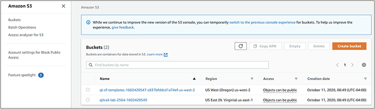
3. You will be presented with a screen showing your existing buckets, as shown here.
4. Click Create Bucket, and then you will be presented with the following screen.

5. Give the bucket a name. In this example, I called it cloud-example. This bucket will just be for us, so keep the Block All Public Access checkbox checked.
6. The next option is related to versioning. In some cases, you may enable versioning if you think you will need to retrieve previous versions of bucket contents. For example, if you were storing temporary screenshots in the bucket but one was overwritten before the desired process performed an action on it, you could go back and retrieve that version if this function were enabled. For this example, we will leave it disabled.
7. The next option is tags, as shown next. Tags are metadata associated with the bucket. Let’s add a few tags for this example. Click Add Tag and then give it a key and a value. For this example, I created the first tag with a key of 1 and a value of sample and then repeated the process to create a tag with a key of 2 and a value of cloud+.

8. The last option is for encrypting the contents of the bucket. Do not enable encryption for this bucket. It is disabled by default, so you will not need to change anything.
9. Lastly, click Create Bucket. Your new bucket will appear in the buckets screen.
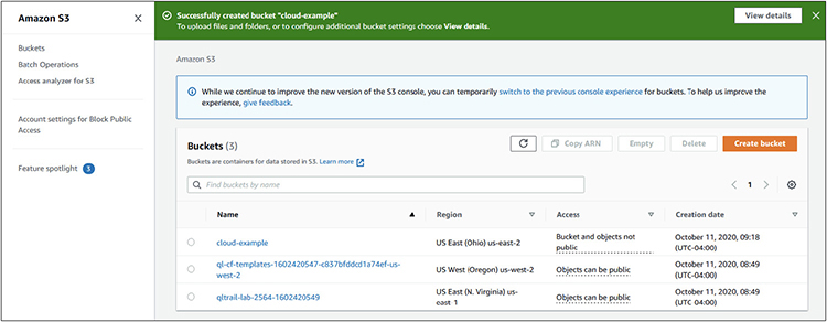
Congratulations! You have just created an Amazon S3 bucket that can be used to store data.
Replicas
Many systems use object storage for replicas. Replicas are essentially copies of one large set of data. They are used to both increase availability and reduce the amount of risk associated with keeping a large amount of data in one location. Replicas are good candidates for object-based storage for several reasons:
• They are large data sets that require a copying mechanism that can run efficiently without requiring expensive error correction or filtering.
• They do not affect user performance SLAs if they are faced with I/O latency, which is often associated with object-based storage and can introduce a performance bottleneck.
Object storage from more than one cloud service provider (CSP) can be used to house replicas of the data so that it will still be available if one CSP is unavailable.
Deduplication Technologies
Deduplication technologies remove redundant data from a storage system to free up space. There are two forms of deduplication technologies: file-level deduplication and block-level deduplication.
File-level deduplication hashes each file on a file system and stores those hashes in a table. Suppose it encounters a file with a hash that is already in its table. In that case, it places a pointer to the existing file on the file system rather than storing the data twice. Imagine a document that is e-mailed to 100 people at an office. Because each person who stores that file would be storing a duplicate on the system, file-level deduplication would save only one copy of that data, with pointers for all the remaining ones. File-level deduplication can remove many duplicates, but it is not nearly as efficient as block-level deduplication.
Block-level deduplication hashes each block that makes up a file. This allows deduplication to occur on the pieces of a file, so deduplication does not require that a file be 100 percent identical to perform deduplication. For example, a user may store nine versions of a spreadsheet. Each version is slightly different from the others as new information was added to it. File-level deduplication would see each file hash as different, so no deduplication would be performed. However, block-level deduplication would see that many of the blocks are the same between these different versions and would store only one block for each duplicate. In this example, block-level deduplication could save up to 90 percent of the space otherwise used.
Compression Technologies
Compression is another method used to reduce space. Some forms of compression result in a loss of information. These forms are known as lossy compression. Other types, known as lossless compression, do not result in a loss of information.
In most cases, you will want to employ lossless compression. Still, there are cases, such as in the transmission of audio or video data, where lossy compression may be utilized to transmit data at a lower quality level when sufficient bandwidth for higher quality is not available or when it would interrupt more time-sensitive data streams. Lossy compression might also be used on a website to increase the speed at which site objects load.
Lossless compression uses mathematical formulas to identify areas of files that can be represented in a more efficient format. For example, an image might have a large section that is all one color. Rather than storing the same color value repeatedly for that section, the lossless compression algorithm would note the range of pixels that contain that color and the color code.
Data BLOB
A binary large object, or BLOB, is a collected set of binary data that is stored as a single, discrete entity in a database management system. By gathering this binary data into larger collections, database administrators are able to better copy large amounts of data between databases with significantly reduced risk of error correction or data filtering.
Storage Access Protocols
Now that you have learned about the various storage technologies that are available, we can turn our attention to the access protocols and applications that utilize these technologies to transmit, shape, and prioritize storage information between hosts and their storage devices.
Fibre Channel
Fibre Channel is a technology for transmitting data between computers at data rates of up to 128 Gbps. IT organizations have made Fibre Channel the technology of choice for interconnecting storage controllers and drives when building high-performance infrastructure requirements. The Fibre Channel architecture is composed of many interconnected individual units, which are called nodes. Each of these nodes has multiple ports. These ports connect the nodes in a storage unit architecture using one of three different interconnection topologies: point-to-point, arbitrated loop, and switched fabric. Fibre Channel also can transmit over long distances. When deployed using optical fiber, it can transmit between devices up to about six miles apart. While Fibre Channel is the transmission medium, it still utilizes SCSI riding on top of it for its commands.

CAUTION Each component in the storage system, from the SAN or NAS, to switches and connected devices such as servers, must support the storage access protocol.
Fibre Channel Protocol
The SCSI commands that ride atop the Fibre Channel transport are sent via the Fibre Channel Protocol (FCP). This protocol takes advantage of hardware that can utilize protocol offload engines (POEs) to increase performance. This assists the host by offloading processing cycles from the CPU, thereby improving system performance.
FCP uses addresses to reference nodes, ports, and other entities on the SAN. Each HBA has a unique worldwide name (WWN), which is an 8-byte identifier similar to an Ethernet MAC address on a network card. There are two types of WWNs on an HBA: a worldwide node name (WWNN), which can be shared by either some or all of the ports of a device, and a worldwide port name (WWPN), which is unique to each port. Fibre switches also have WWPNs for each switch port. Other devices can be issued a worldwide unique identifier (WWUI) so that they can communicate on the SAN.
The frames in Fibre Channel Protocol consist of three components: an encapsulating header called the start-of-frame (SOF) marker, the data frame itself, and the end-of-frame (EOF) marker. This encapsulated structure enables the Fibre Channel frames to be transported across other protocols, such as TCP, if desired.
Fibre Channel over Ethernet
Fibre Channel over Ethernet (FCoE) enables the transport of Fibre Channel traffic over Ethernet networks by encapsulating Fibre Channel frames. Fibre Channel over Ethernet can utilize Ethernet technologies up to 10 Gigabit Ethernet (10GigE) networks and higher speeds as they are developed while still preserving the Fibre Channel protocol.
Ethernet
Ethernet is an established standard for connecting computers to a local area network (LAN). Ethernet is a relatively inexpensive and reasonably fast LAN technology, with speeds ranging from 10 Mbps to 10 Gbps. Because it enables high-speed data transmission and is relatively inexpensive, Ethernet has become ubiquitous in IT organizations and the Internet. Ethernet technology operates at the OSI model’s physical and data link layers (layers 1 and 2). Although it is capable of high speeds, it is limited by both the length and the type of cables over which it travels. The Ethernet standard divides its data traffic into groupings called frames. These frames are utilized by storage protocols to deliver their data from one point to another, such as from a NAS device to a server.
TCP/IP
Internet Protocol (IP) is a protocol that operates at the network layer of the OSI model (layer 3) and provides unique IP addresses and traffic-routing capabilities. Computers utilizing the IPv4 protocol are addressed using dotted decimal notation with four octets divided by dots. As the name suggests, IP is the protocol that enables the Internet. Like Ethernet networks, it is ubiquitous in IT departments. TCP/IP provides a proven, relatively inexpensive, and well-understood technology on which to build storage networks.
Transmission Control Protocol (TCP) is a protocol that provides reliable transport of network data through error checking. TCP uses ports that are associated with certain services and other ports that can be dynamically allocated to running processes and services. TCP is most often combined with IP, and it operates at the transport layer of the OSI model (layer 4).
Internet Fibre Channel Protocol
Internet Fibre Channel Protocol (iFCP) enables the transport of Fibre Channel traffic over IP networks by translating Fibre Channel addresses to IP addresses and Fibre Channel frames to IP packets. iFCP reduces overhead compared with other protocols that transport Fibre Channel over IP because it does not use tunneling to connect Fibre Channel devices.
Internet Small Computer System Interface
Internet Small Computer System Interface (iSCSI) is a protocol that utilizes serialized IP packets to transmit SCSI commands across IP networks and enables servers to access remote disks as if they were locally attached. iSCSI “initiator” software running on the requesting entity converts disk block-level I/O into SCSI commands that are then serialized into IP packets that traverse any IP network to their targets. At the destination storage device, the iSCSI packets are interpreted by the storage device array into the appropriate commands for the disks it contains. Figure 3-2 shows an example of how multiple servers can leverage iSCSI to connect to shared storage over an IP network.
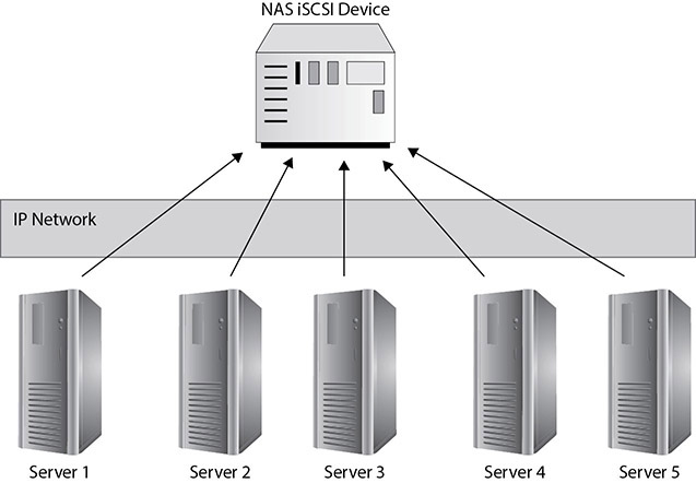
Figure 3-2 Using iSCSI over an IP network
iSCSI is limited by the transmission speeds of the Ethernet network it travels over; when administrators design iSCSI networks, they should pay close attention to the design to isolate the storage network traffic from the data network traffic. Although its performance is not as high as that of a Fibre Channel SAN, iSCSI can be an inexpensive entry into shared storage for IT departments or a training ground using repurposed equipment for administrators who want to get hands-on experience with storage networking. iSCSI can be implemented on a NAS device or on a general-purpose machine. iSCSI’s flexibility and ease of implementation make it a popular and versatile storage protocol.
The iSCSI address given to an initiator is known as an iSCSI qualified name (IQN). Initiators reside on clients in an iSCSI network, and initiators connect to targets such as storage resources over the iSCSI network. An IQN uses the following naming convention: iqn.yyyy-mm.naming-authority:unique name.
Nonvolatile Memory Express Over Fabrics
Nonvolatile Memory Express Over Fabrics (NVMe-oF) is a storage network protocol that can run over high-speed storage protocols such as InfiniBand or FC and Ethernet. It is specially designed to work well with flash SSD storage over the network. NVMe-oF is based on the NVMe storage protocol used for high-speed SSD storage over the PCI-e bus. NVMe-oF can directly share data in memory and without using CPU cycles, so the CPU is not overburdened. This sharing occurs using the Remote Direct Memory Access (RDMA) protocol.
EXAM TIP NVMe-oF is an ideal storage networking protocol to use when working primarily with flash-based storage.
Storage Provisioning
Now that you understand the technologies, protocols, and applications for moving storage data around networks, we will explore how that data is presented to computers. Data can be made available to computers in many ways, with varying degrees of availability and security.
Performance
Everyone has an expectation of performance for a system, and these expectations tend to increase as computing power increases. Storage systems also cannot stay the same. They must keep up with the application and end-user demand. To do this, storage systems need a way to measure performance in a meaningful way. The most common method is input/output operations per second (IOPS). Storage must be provisioned to provide the required IOPS to the systems that utilize that storage. This requires having an understanding of the read and write throughput that different RAID sets and drive types can produce, as well as the performance enhancements that can be gained from storage tiering.
IOPS
IOPS is a measurement of how much data is provided over a period of time. It is usually expressed in bits per second (bps), bytes per second (Bps), megabytes per second (MBps), or gigabytes per second (GBps). Drives are typically rated regarding the IOPS they can support. Hard disk drives may provide values for average latency and average seek time, or those values can be computed from their spindle speed. The formula for IOPS is as follows:
IOPS = 1 / (average latency + average seek time)
For example, if a SATA drive running has an average latency of 3.2 ms and an average seek time of 4.7 ms, we would take 1 / (.0032 + .0047), which gives us 126.58, or 127 IOPS rounded to the nearest integer.
When drives are combined together into a RAID array, the RAID technology will utilize a combination of these IOPS. For example, a RAID 5 array of six drives, each with 127 IOPS, would provide 635 IOPS. The array would have five drives for striping and one for parity, so that is 5 times 127 to produce the 635 read IOPS. There is a difference between read and write IOPS, as will be explained next.
Read/Write Throughput
The RAID types chosen, as well as the caching settings, can determine how many IOPS will be produced by a logical volume. Read and write throughput are also expressed as either sequential reads or writes or random reads or writes. Sequential reads are when data is read from contiguous portions of the disk, while random reads are when data is read from various locations on the disk. It is more efficient to pull data from adjacent parts of the disk because then drives do not need to spend as much time seeking the data.
Caching can also have an impact on read and write IOPS. Caching settings can be optimized for reading or writing or a little of both. A cache can hold files that were recently requested in case they are asked for again, improving read speeds when those files are fetched from cache instead of disk. Similarly, files can be placed in cache and then written to the disk when it is most efficient to store the data so that the application does not need to wait for the data to actually be written to the disk if it exists in the write cache. The four read/write throughput values are thus as follows:
• Random read IOPS The average number of read I/O operations that can be performed per second when the data is scattered around the disk
• Random write IOPS The average number of write I/O operations that can be performed per second when the data must be written to scattered portions of the disk
• Sequential read IOPS The average number of read I/O operations that can be performed per second when the data is located in contiguous sections of the disk
• Sequential write IOPS The average number of write I/O operations that can be performed per second when the data must be written to contiguous sections of the disk
Storage Tiers
Storage tiering is an essential part of storage optimization. Not all data will be requested all the time, so it does not have to be treated the same way. Tiering combines multiple classes of storage into a single storage pool to intelligently satisfy storage demands. Higher-speed storage is used for the most often needed data or that the system predicts will be required. In contrast, data that is requested less often is moved down to lower tiers.
For example, the highest-speed storage tier could be made up of 5TB of high-speed SLC SSD storage, while the second tier would be 10TB of lower-speed MLC SSD storage, the third tier 20TB of TLC SSD storage, and the fourth tier 50TB of 15k SAS storage drives that spin at 15,000 rotations per minute. This is shown in Figure 3-3. The application would see an 85TB pool of storage available to it that is made up of these different types of storage. The storage system intelligently moves the data around on the different tiers so that data is most often served from the highest speed storage.
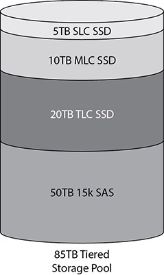
Figure 3-3 Tiered storage pool

TIP Solid-state storage was discussed in Chapter 2. There are three common types of SSDs in use today. Single-level cell (SLC) is the fastest but can store only one binary value in a cell, making it the SSD storage type with the smallest capacity. Looking at it another way, SLC has the highest cost per gigabyte. Multilevel cell (MLC) can store two binary values in each cell but is slower than SLC. Triple-level cell (TLC) is the slowest of the three but has the highest capacity because it can store three binary values per cell. This makes TLC the lowest cost per gigabyte in SSDs.
Logical Unit Numbers
LUNs, introduced earlier, have been around for a long time and were originally used to identify SCSI devices as part of a DAS solution for higher-end servers. Devices along the SCSI bus were assigned a number from 0 to 7, and SCSI 2 utilized 0 to 15, which designated the unique address for the computer to find that device. In storage networking, LUNs operate as unique identifiers, but now they are much more likely to represent a virtual hard disk from a block of allocated storage within a NAS device or a SAN. Devices that request I/O process are called initiators, and the devices that perform the operations requested by the initiators are called targets. Each target can hold up to eight other devices, and each of those devices is assigned a LUN.
Network Shares
Network shares are storage resources available across the network that appear as if they are resources on the local machine. Traditionally, network shares are implemented using the SMB protocol when using Microsoft products and the NFS protocol in Linux. It is also possible to share the same folder over NFS and SMB so that both Linux and Windows clients can access it. Access to these shares happens within an addressable file system as opposed to using block storage.
Zoning and LUN Masking
SANs are designed with high availability and performance in mind. In order to provide the flexibility that system administrators demand for designing solutions that utilize those capabilities, servers need to be able to mount and access any drive on the SAN. This flexible access can create several problems, including disk resource contention and data corruption. To mitigate these problems, storage devices can be isolated and protected on a SAN by utilizing zoning and LUN masking, which allow for dedicating storage on the SAN to individual servers.
Zoning controls access from one node to another. It enables the isolation of a single server to a group of storage devices or a single storage device or associates a set of multiple servers with one or more storage devices. Zoning is implemented at the hardware level on Fibre Channel switches and is configured with what is referred to as “hard zoning” on a port basis or “soft zoning” using a WWN. In Figure 3-4, the Fibre Channel switch is controlling access to the red server and the blue server to connect to storage controllers 0–3. It grants access to the blue server to the LUNs on controllers 0 and 3, while the red server is granted access to all LUNs on all storage controllers.
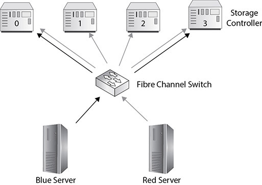
Figure 3-4 Zoning using a Fibre Channel switch
LUN masking is executed at the storage controller level instead of at the switch level. By providing LUN-level access control at the storage controller, the controller itself enforces access policies to the devices. LUN masking provides more detailed security than zoning because LUNs allow for sharing storage at the port level. In Figure 3-5, LUN masking is demonstrated as the blue server is granted access from the storage controller to LUNs 0 and 3. In contrast, the red server is granted access to all LUNs.

Figure 3-5 LUN masking using the storage controller
Multipathing
Whereas zoning and LUN masking are configuration options that limit access to storage resources, multipathing is a way of making data more available or fault-tolerant to the computers that need to access it. Multipathing does exactly what its name suggests, in that it creates multiple paths for the machine to reach the storage resources it is attempting to contact.
The redundant paths in multipathing are created by a combination of hardware and software resources. The hardware resources are multiple NICs, CNAs, or HBAs deployed to a single computer. These multiple adapters provide options for the software to run in multipath mode, which allows it to use either of the adapters to send traffic over in case one of them were to fail.
Setting up multipathing on the computer, however, is not enough to ensure high availability of the applications designed to run on it. The entire network infrastructure that the data traffic travels upon should be redundant so that a failure of any one component will not interrupt the storage data traffic. This means that to implement an effective multipath solution, redundant cabling, switches, routers, and ports on the storage devices must be considered. Enabling this kind of availability may be necessary to meet the business requirements of the applications being hosted, but such a configuration can be very expensive.
Provisioning Model
Cloud storage administrators will need to determine how to best provision storage depending on how the storage will be utilized and the available storage at hand. Some storage needs increase slowly, while others increase quickly. There are two options for provisioning storage. One is known as thick provisioning and the other as thin provisioning. Each has its own set of benefits and drawbacks.
Virtual hard disks on hypervisors can be provisioned as a thick disk or a thin disk. The size of a thick disk (termed a fixed disk in Microsoft Hyper-V) is specified and allocated during the virtual disk creation. A thin disk (termed a dynamically expanding disk in Microsoft Hyper-V) starts out small. It adds space as required by the virtual machine.
While the different virtualization manufacturers use different terms to define their virtual disks, the concepts are similar. Whether you are using Hyper-V, VMware ESXi, or XenServer, you still need to decide which type of disk to use for which application. If you are concerned about disk space, then using a thin disk or dynamically expanding disk would be the best option. If size is not a concern, then you could use a fixed-size or thick disk.
Now that you understand the basics, let’s look at thin and thick provisioning in more detail.
Thick Provisioning
Thick provisioning allocates the entire size of the logical drive upon creation. This means that the virtual disk is guaranteed and consumes whatever amount of disk space is specified during the creation of that virtual disk. Thin provisioning ensures that space will not be claimed by some other application and keeps the provisioned storage in contiguous space on the disk. Thick provisioning provides better performance because the drive size is not being built as the application requires more drive space. Thick provisioning is best suited for volumes that are expected to multiply in size or for those that require dedicated performance.
For example, a thick-provisioned volume of 400GB will consume 400GB of space on the storage system. This storage will be allocated entirely upon creation and made available to the system.
Thin Provisioning
Thin provisioning allocates only the space that is actually consumed by the volume. For example, a 400GB thin-provisioned volume will start off consuming zero bytes of storage. As data is written to the volume, the storage system will continue to allocate more storage out of a storage pool until the volume reaches its max of 400GB. This results in storage space allocated from wherever there is free space on the drive at the time it is needed, so not all space assigned to the thin-provisioned volume will be in contiguous space.
Thin provisioning does not have the same performance level as a thick disk and needs to be monitored closely to prevent running out of available disk space, since storage space is, by definition, overcommitted.
Here are a few things to keep in mind when comparing thin and thick provisioning to determine which one works best in the organization’s environment. First, determine the system’s performance requirements, including the amount of data reads and writes you expect the system to perform. Each time new data is added to a thin-provisioned disk, space from the pool on which the thin-provisioned disk resides is allocated to the disk. This can lead to extensive fragmentation of the thin-provisioned volume if it grows frequently and rapidly. For example, an application that writes a lot of data to the drive, such as a database application, would not perform as well on a thin-provisioned disk. On the other hand, if space is a concern and a web server is not writing to the virtual disk that often, a thin-provisioned disk would be more appropriate.
Second, determine how often the data will grow. Excessive growth of thin-provisioned disks can fill up the storage pool on which the disks reside if overprovisioning, discussed next, is not properly controlled.
EXAM TIP The application workload is often the determining factor in choosing the type of virtual disk.
Storage Overprovisioning
Storage overprovisioning, also known as overcommitting or oversubscribing, is the process of creating multiple volumes using thin provisioning with a total maximum size that exceeds available storage. Overprovisioning is often done because some volumes will never utilize the maximum available, yet applications perform better when there is some space available for temporary data. However, storage administrators must monitor overprovisioned storage closely to ensure that it does not fill up and cause downtime to the systems that are provisioned from it.
Each of the major virtualization manufacturers has different terms when describing virtual disk configurations. For example, if you are using Microsoft Hyper-V, you would have the option of making a dynamically expanding virtual disk, a fixed virtual disk, or a differencing virtual disk. If you are creating a fixed-size disk, you would specify the size of the disk when it is created. If you are creating a dynamically expanding virtual disk, the disk starts at a small size and adds storage as needed.
Encryption Requirements
Disk encryption is quickly becoming a minimum requirement for regulated industries and for protecting the data of cloud consumers. Some customers require their volumes to be encrypted so that other tenants or the CSP cannot read their data.
Disk encryption takes an entire drive and converts it to a form that is unreadable unless the decryption key is provided. Disk encryption can be performed on local drives or removable media. The process is mostly transparent to the user. Users provide their decryption key when they log onto the computer. From that point on, files are encrypted when stored and decrypted when opened without additional interaction. Disk encryption is also referred to as full disk encryption (FDE). Some software-based disk encryption methods encrypt all contents but not the Master Boot Record (MBR), the section of the disk that describes the logical partitions and contains the boot loader information that the computer uses to start up the operating system when the computer is powered up.
In contrast, hardware disk encryption methods are able to encrypt the contents and the MBR. Hardware disk encryption does not store the decryption key in memory. Drives encrypted with hardware disk encryption are also known as self-encrypting drives (SEDs). Many disk encryption systems support trusted platform module (TPM), a processor on the system mainboard that can authenticate the encrypted hard drive to the system to prevent an encrypted drive from being used on another system.
Some disk encryption limitations include the fact that once a user is logged in, the entire disk is available to them. Malicious code or a lost password could allow access to the entire drive even if it is encrypted. Additionally, some disk encryption systems have been circumvented, including those with TPM, by stealing the keys stored in memory shortly after a cold shutdown (not a controlled shutdown) before memory data fully degrades. Still, disk encryption is an effective way to prevent unauthorized access to data stored on local drives and removable disks.
Tokenization
Tokenization can separate sensitive data from storage media that does not have a high enough security classification. Tokens are identifiers that can be mapped to sensitive data. The token is just an identifier and cannot create the data without interfacing with the tokenization system.
A system storing data on a cloud might store public data and then store a token in place of each sensitive data element, such as personally identifiable information (PII) or protected health information (PHI). The PII or PHI would be stored in the tokenization system, and the public cloud storage would retain the token for that information. When retrieving the data, the system would retrieve public data directly from the cloud storage but would need to query the tokenization system to pull out the sensitive data, a process known as detokenization.
Storage Protection
Storage protection guards against data loss, corruption, or unavailability. Users expect their data to be present when they request it, and data loss is almost always considered unacceptable to cloud consumers. Storage protection must guard against equipment failures, site failures, user error, data corruption, malware, and other threats that could damage data integrity or availability.
High Availability
HA refers to systems that are available almost 100 percent of the time. These systems are usually measured in terms of how many “nines” of availability they offer. For example, a system that offers 99.999 percent availability is offering 5 nines of availability. This equates to 5.39 minutes of downtime in a year.
HA systems achieve such availability through redundancy of components and sites. HA systems might also replicate data to multiple sites, colocations (COLOs), or cloud services to protect against site failure or unavailability. Storage replication is discussed after failover zones.
Failover Zones
HA systems utilize clusters to divide operations across several systems. Some systems are active-active, where all systems can service application requests. In contrast, others are active-passive, where one or more systems service requests while one or more remain in a standby state until needed. Active-active systems must retain enough available resources to handle the remaining load if a system in the cluster becomes unavailable. This is known as N + 1 redundancy because they can suffer the loss of one system.
HA systems require regular maintenance, and yet in the 5 nines example, 5.39 minutes of downtime per year is hardly enough time to perform regular maintenance. HA systems accomplish this by performing upgrades to redundant equipment independently. In a cluster, the services on one cluster node are failed over to other cluster nodes. That node is upgraded and then services are failed back to it. Maintenance or upgrades continue on the other nodes in the same fashion until all are upgraded. Throughout the process, the user does not experience any downtime. Clustering typically requires some level of shared storage where each node can access the same storage. When shared storage is not available, systems will use some form of replication to keep each system consistent with other systems. For example, when failover is performed across sites, replication is usually required to keep both sites consistent.
Storage Replication
Storage replication transfers data between two systems so that any changes to the data are made on each node in the replica set. A replica set consists of the systems that will all retain the same data. Multiple sites are used to protect data when a single site is unavailable and to ensure low-latency availability by serving data from sources that are close to the end user or application.
Regional Replication
Regional replication uses replication to store data at a primary site and a secondary site. In regional replication, the secondary site is located in a different region from the primary site so that conditions affecting the primary site are less likely to affect the secondary site. Site unavailability is usually the result of a natural disaster such as a flood, fire, tornado, or hurricane. Many data centers are placed in regions where natural disasters are less common. For example, you will not find many data centers on the Florida coast. Not only is this land very expensive but it is also prone to floods and hurricanes, which could render the site unavailable. Redundant sites are usually chosen in different regions that are far enough apart from one another that a single disaster will not affect both sites.
When implementing sites in different regions, also consider the power distribution method. Choose regions that are serviced by different power suppliers so that a disruption in the power network will not affect both sites.
Data will need to be replicated to these regions. This requires a connection between the data centers. This can be a leased line such as an MPLS network or dark fibre (fiber-optic cable that is not owned and operated by a telco), or it could be a VPN tunnel over a high-speed Internet link. Ensure that the link between the sites will support the amount of replication data plus some overhead and room for spikes. Some Internet service providers will allow for a consistent data rate with bursting for the occasional large transfer. Bursting allows the connection to exceed the normal data transmission limits, but it comes at a charge from the ISP.
Multiregional Replication
Multiregional replication replicates data between many different sites in multiple regions. Replication schemes should be planned so that the entire replica set can be consistent with a minimum of effort and yet still provide redundancy in case of site link failures.
CAUTION Regulations may require that data remain within specific countries or regions. Be sure to check to see if data can be replicated outside the country before enabling such features. Cloud systems can be restricted to a specific country or region, if necessary.
Each site typically has one or more replication partners, but they will not replicate with all sites. This saves on bandwidth costs and latency, since longer-distance links will incur additional latency and cost more to operate. A hub-and-spoke model is often utilized, with redundant links added in to protect against site link failure. This is depicted in Figure 3-6.

Figure 3-6 Multiregional replication
Synchronous and Asynchronous Replication
Two forms of replication can be used to keep replica sets consistent: synchronous and asynchronous. Synchronous replication writes data to the local store and then immediately replicates it to the replica set or sets. The application is not informed that the data has been written until all replica sets have acknowledged receipt and storage of the data. Asynchronous replication stores the data locally and then reports to the application that the data has been stored. It then sends the data to replication partners at its next opportunity.
Synchronous replication requires high-speed, low-latency links between sites in order to ensure adequate application performance. Synchronous replication ensures greater consistency between replication partners than asynchronous replication.
Asynchronous replication can tolerate fluctuations that are more significant in latency and bandwidth, but not all members of the replica set may be fully consistent in a timely manner if latency is high or bandwidth is low. This can lead to issues with multiple concurrent access from different sites that are dependent upon transactions being current. Figure 3-7 shows the multiregional replication scheme with a combination of asynchronous and synchronous replication. The sites that are farther away are using asynchronous replication, while the closer sites with lower latency are using synchronous replication.
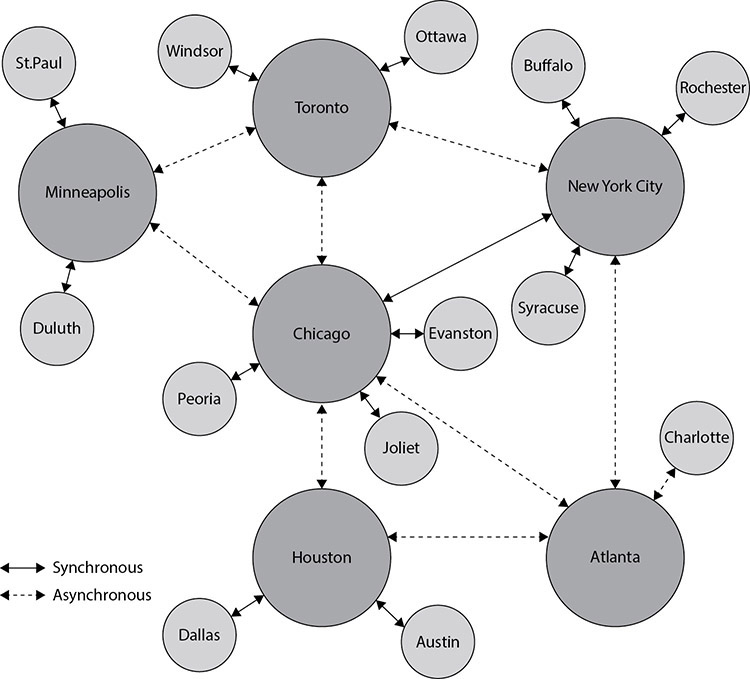
Figure 3-7 Synchronous and asynchronous multiregional replication
Chapter Review
Storage networking is an essential component of the CompTIA Cloud+ exam, and it is the foundation of a successful cloud infrastructure. This chapter discussed storage types and technologies, how to connect storage to devices, how to provision storage and make it available to devices, and how to protect storage availability through replication and redundancy.
The chapter began with a discussion on storage types and technologies. Understanding when to use the different storage types is important for optimizing a cloud deployment. These include direct attached storage (DAS), consisting of one or more drives that are connected to a single machine to provide block-level storage; SAN storage that is made available to one or more machines at the block level; NAS shares that make data available to multiple machines at the file level; and object storage, a system that stores and retrieves data based on its metadata, not on its location within a hierarchy.
In addition to the four storage types, this section covered two storage technologies. These technologies are deduplication and compression, and they are designed to improve storage efficiency. Deduplication improves storage efficiency by removing unnecessarily redundant data, while compression improves efficiency by decreasing the amount of storage required to store the data. Lossy compression results in some reduction in data quality, while lossless does not change the data when it is decompressed.
Storage needs to be connected to devices for it to be useful. The second section of this chapter provided details on storage connectivity. Connecting to storage can be simple, as in the case of DAS, since it is connected to only one machine. Still, NAS and a SAN can involve complex networking to ensure adequate storage performance and reliability needed in today’s cloud environments. This includes how devices are connected to storage networks or how NAS is connected to traditional networks, as well as the benefits of each connection type. Connection types include Fibre Channel, FCP, FCoE, Ethernet, IP, iFCP, and iSCSI.
The next section covered how storage is provisioned. The first step is to create storage that meets the application’s performance requirements. SAN storage may be created from many disks, and the portions that are carved out from those disks are called LUNs. Next, storage is made available only to the devices that need it through the use of zoning and LUN masking. There are some options when provisioning storage on how much space is allocated when new storage is created. Thin and thick provisioning offer two different methods to provision storage. Thick provisioning consumes all the allocated storage immediately, while thin provisioning allocates only what is actually used. Thin provisioning can help companies maximize capacity and utilization, but it can affect performance. Thick provisioning results in underutilized resources in order to offer more reliable performance.
The chapter closed with a discussion on some methods used to protect storage against data loss, corruption, or unavailability. The concept of high availability (HA) was presented first. HA systems are available almost 100 percent of the time. Next, storage replication was discussed. Storage replication transfers data between two systems so that any changes to the data are made on each node in the replica set. A replica set consists of the systems that will all retain the same data. Multiple sites are used to protect data when a single site is unavailable and to ensure low-latency availability by serving data from sources that are close to the end user or application.
Questions
The following questions will help you gauge your understanding of the material in this chapter. Read all the answers carefully because there might be more than one correct answer. Choose the best response(s) for each question.
1. Which type of storage system is directly attached to a computer and does not use a storage network between the computer and the storage system?
A. NAS
B. SAN
C. DAS
D. Network share
2. Which of the following characteristics describe a network attached storage (NAS) deployment?
A. Requires expensive equipment to support
B. Requires specialized skill sets for administrators to support
C. Delivers the best performance of any networked storage technologies
D. Provides great value by utilizing an existing network infrastructure
3. Which statement would identify the primary difference between NAS and DAS?
A. NAS cannot be shared and accessed by multiple computers.
B. DAS provides fault tolerance.
C. DAS does not connect to networked storage devices.
D. NAS uses an HBA and DAS does not.
4. Which storage type can take advantage of Universal Naming Convention addressable storage?
A. SAN
B. NAS
C. DAS
D. SATA
5. Which storage type provides block-level storage?
A. SAN
B. NAS
C. DAS
D. SATA
6. Which of the following connects a server and a SAN and improves performance?
A. Network interface card
B. Host bus adapter
C. Ethernet
D. SCSI
7. Which of the following protocols allows Fibre Channel to be transmitted over Ethernet?
A. HBA
B. FCoE
C. iSCSI
D. SAN
8. Which of the following is considered a SAN protocol?
A. FCP
B. IDE
C. SSD
D. DTE
9. Which of the following allows you to connect a server to storage devices with speeds of 128 Gbps?
A. Ethernet
B. iSCSI
C. Fibre Channel
D. SAS
10. Which of the following uses IP networks that enable servers to access remote disks as if they were locally attached?
A. SAS
B. SATA
C. iSCSI
D. Fibre Channel
11. Warren is a systems administrator working in a corporate data center, and he has been tasked with hiding storage resources from a server that does not need access to the storage device hosting the storage resources. What can Warren configure on the storage controller to accomplish this task?
A. Zoning
B. LUN masking
C. Port masking
D. VLANs
12. Which of the following would increase availability from a virtualization host to a storage device?
A. Trunking
B. Multipathing
C. Link aggregation
D. VLANs
13. A website administrator is storing a large amount of multimedia objects in binary format for the corporate website. What type of storage object is this considered to be?
A. BLOB
B. Replica
C. Metadata
D. Object ID
14. Which of the following allows you to provide security to the data contained in a storage array?
A. Trunking
B. LUN masking
C. LUN provisioning
D. Multipathing
15. Which provisioning model would you use if data is added quickly and often? The solution must ensure consistent performance.
A. Thin provisioning
B. Thick provisioning
C. Overprovisioning
D. Encryption
16. Which HA solution involves multiple servers that each service requests concurrently but can assume the load of one member if that member fails?
A. Active-passive
B. Active-active
C. Passive-passive
D. Passive-active
17. Which of the following are requirements for adequate application performance when using synchronous replication? (Choose two.)
A. Object storage
B. Low latency
C. Multipathing
D. High-speed links
Answers
1. C. DAS is a storage system that directly attaches to a server or workstation without a storage network in between the devices.
2. D. Network attached storage can utilize existing Ethernet infrastructures to deliver a low-cost solution with good performance.
3. C. DAS is a storage system that directly attaches to a server or workstation without a storage network in between the devices.
4. B. NAS appears to the client operating system as a file server, which allows it to use Universal Naming Convention addressable storage.
5. A. A SAN is a storage device that resides on its own network and provides block-level access to computers that are attached to it.
6. B. An HBA card connects a server to a storage device and improves performance by offloading the processing required for the host to consume the storage data without having to utilize its own processor cycles.
7. B. Fibre Channel over Ethernet (FCoE) enables the transport of Fibre Channel traffic over Ethernet networks by encapsulating Fibre Channel frames over Ethernet networks.
8. A. The Fibre Channel Protocol is a transport protocol that transports SCSI commands over a Fibre Channel network. These networks are used exclusively to transport data in FC frames between storage area networks and the HBAs attached to servers.
9. C. You can use Fibre Channel to connect servers to shared storage devices with speeds of up to 128 Gbps. Fibre Channel also comes in 64, 32, 16, 8, 4, and 2 Gbps versions.
10. C. iSCSI utilizes serialized IP packets to transmit SCSI commands across IP networks and enables servers to access remote disks as if they were locally attached.
11. B. LUN masking is executed at the storage controller level instead of at the switch level. By providing LUN-level access control at the storage controller, the controller itself enforces access policies to the devices, making it more secure. This is the reason that physical access to the same device storing the LUNs remains “untouchable” by the entity using it.
12. B. Multipathing creates multiple paths for the computer to reach the storage resources it is attempting to contact, improving fault tolerance and possibly speed.
13. A. A BLOB is a collection of binary data that is stored as a single entity. BLOBs are primarily used to store images, videos, and sound.
14. B. LUN masking enforces access policies to storage resources, and these storage policies make sure that the data on those devices is protected from unauthorized access.
15. B. Thick provisioning would consume all the allocated space upon creation of the LUN, but performance would be consistent for a LUN that expects data to be added quickly and often because storage would not need to be continually allocated to the LUN and the storage would not be fragmented.
16. B. Active-active solutions allow for all systems to service application requests.
17. B, C. Synchronous replication requires high-speed, low-latency links in between sites in order to ensure adequate application performance.