CHAPTER 3
Ethernet Basics
The CompTIA Network+ certification exam expects you to know how to
• 2.1 Given a scenario, deploy the appropriate cabling solution
• 2.2 Given a scenario, determine the appropriate placement of networking devices on a network and install/configure them
• 4.6 Explain common mitigation techniques and their purposes
To achieve these goals, you must be able to
• Define and describe Ethernet
• Explain early Ethernet implementations
• Describe ways to enhance and extend Ethernet networks
In the beginning, there were no networks. Computers were isolated, solitary islands of information in a teeming sea of proto-geeks who banged out binary messages with wooden clubs and wore fur pocket protectors. Okay, maybe it wasn’t that bad, but if you wanted to move a file from one machine to another, you had to use Sneakernet, which meant you saved the file on a disk, laced up your tennis shoes, and hiked over to the other system.
All that walking no doubt produced lots of health benefits, but frankly, proto-geeks weren’t all that into health benefits—they were into speed, power, and technological coolness in general. (Sound familiar?) It’s no wonder, then, that geeks everywhere agreed on the need to replace walking with some form of networking technology that connects computers together to transfer data at very high speeds.
This chapter explores the networking technology that eventually took control of the industry, Ethernet. We’ll start with basic terminology, then look at two early forms of Ethernet. The chapter finishes with a discussion on enhancing and expanding Ethernet networks.
Historical/Conceptual
Ethernet
In 1973, Xerox answered the challenge of moving data without sneakers by developing Ethernet, a networking technology standard based on a bus topology. The original Ethernet used a single piece of coaxial cable to connect several computers, enabling them to transfer data at a rate of up to three million bits per second (Mbps). Although slow by today’s standards, this early version of Ethernet was a huge improvement over manual transfer methods and served as the foundation for all later versions of Ethernet.
Ethernet remained a largely in-house technology within Xerox until 1979, when Xerox decided to look for partners to help promote Ethernet as an industry standard. Xerox worked with Digital Equipment Corporation (DEC) and Intel to publish what became known as the Digital/Intel/Xerox (DIX) standard. The DIX Ethernet standard improved on the original Ethernet standard, increasing speed to a screaming 10 Mbps.
These companies then did something visionary: they transferred (one might also say gave away) control of the Ethernet standard to the Institute of Electrical and Electronics Engineers (IEEE), which, in turn, created the 802.3 (Ethernet) committee that continues to control the Ethernet standard to this day. By transferring control to IEEE, Ethernet became an open standard, enabling anyone to make interchangeable Ethernet equipment. Making Ethernet an open standard made Ethernet much cheaper than any alternative technology and certainly contributed to Ethernet winning the marketplace.
802.3 Standards
The 802.3 committee defines wired network standards that share the same basic frame type and network access method. Each of these variants is under the IEEE 802.3 standard, each with its own identifier. Here’s a small selection of 802.3 standards:
• 802.3i 10 Mbps Ethernet using twisted pair cabling (1990)
• 802.3ab Gigabit Ethernet over twisted pair (1999)
• 802.3by 25 Gigabit Ethernet over fiber (2016)
Because the technologies share essential components, you can communicate among them just fine. The implementation of the network might be different, but the frames remain the same.

NOTE There have been four different Ethernet frame types defined over the years, but only one, the Ethernet II frame type, is used today. Every version of 802.3 Ethernet uses the same Ethernet II frame.
Ethernet’s designers faced the same challenges as the designers of any network: how to send data across the wire, how to identify the sending and receiving computers, and how to determine which computer should use the shared cable at what time. The engineers resolved these issues by using data frames that contain MAC addresses to identify computers on the network and by using a process called CSMA/CD (discussed shortly) to determine which machine should access the wire at any given time. You saw some of this in action in Chapter 1, “Network Models,” but now I need to introduce you to a bunch of additional terms.
NOTE The source for all things Ethernet is but a short click away on the Internet. For starters, check out www.ieee802.org.
Test Specific
Ethernet Frames
All network technologies break data transmitted between computers into smaller pieces called frames, as you’ll recall from Chapter 1. Using frames addresses two networking issues. First, frames prevent any single machine from monopolizing the shared bus cable. Second, they make the process of retransmitting lost data more efficient.

EXAM TIP The terms frame and packet are sometimes used interchangeably, but this book uses the terms strictly. You’ll recall from Chapter 1 that frames at Layer 2 are based on MAC addresses; packets are associated with data assembled by the IP protocol at Layer 3 of the OSI seven-layer model.
The process you saw in Chapter 1 of transferring a word processing document between two computers illustrates these two issues. First, if the sending computer sends the document as a single huge frame, the frame will monopolize the cable and prevent other machines from using the cable until the entire file gets to the receiving system. Using relatively small frames enables computers to share the cable easily—each computer listens on the segment, sending a few frames of data whenever it detects that no other computer is transmitting. Second, in the real world, bad things can happen to good data. When errors occur during transmission, the sending system must retransmit the frames that failed to get to the receiving system in good shape. If a word processing document were transmitted as a single massive frame, the sending system would have to retransmit the entire frame—in this case, the entire document. Breaking the file up into smaller frames enables the sending computer to retransmit only the damaged frames. Because of these benefits—shared access and more efficient retransmission—all networking technologies use frames.
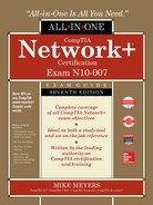
In Chapter 1, you saw a generic frame. Let’s take what you know of frames and expand on that knowledge by inspecting the details of an Ethernet frame. A basic Ethernet frame contains five fields: the destination—the MAC address of the frame’s recipient; the source—the MAC address of the sending system; the type of the data; the data itself; and a frame check sequence. Figure 3-1 shows these components. Transmission of a frame starts with a preamble and can also include some extra filler called a pad. Let’s look at each piece.
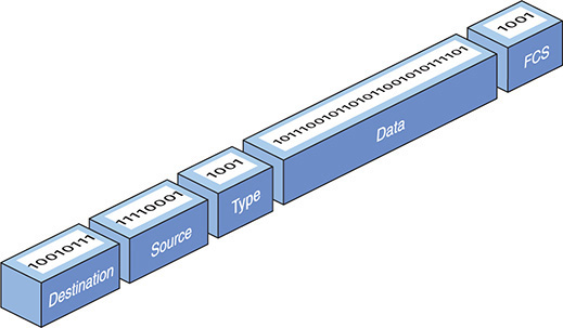
Figure 3-1 Ethernet frame
Preamble
A preamble, a 7-byte series of alternating ones and zeroes followed by a 1-byte start frame delimiter, always precedes a frame. The preamble gives a receiving NIC time to realize a frame is coming and to know exactly where the frame starts. The preamble is added by the sending NIC.
MAC Addresses
Each NIC on an Ethernet network must have a unique identifying address. Ethernet identifies the NICs on a network using special 48-bit (6-byte) binary addresses known as MAC addresses.
EXAM TIP The CompTIA Network+ exam might describe MAC addresses as 48-bit binary addresses or 6-byte binary addresses.
In a bus network, all the connected computers could see all traffic. The destination address in the frame enabled NICs to examine each frame and process only frames intended for them. The source address in the frame enabled the recipient to respond accurately.
Type
An Ethernet frame may carry one of several types of data. The type field helps the receiving computer interpret the frame contents at a very basic level. This way the receiving computer can tell if the frame contains IPv4 data, for example, or IPv6 data. (See Chapter 6 for more details on IPv4; I cover IPv6 in Chapter 12.)
The type field does not tell you if the frame carries higher-level data, such as an e-mail message or Web page. You have to dig deeper into the data section of the frame to find that information.
Data
The data part of the frame contains whatever payload the frame carries. If the frame carries an IP packet, that packet will include extra information, such as the IP addresses of both systems.
Pad
The minimum Ethernet frame is 64 bytes in size, but not all of that has to be actual data. If an Ethernet frame has fewer than 64 bytes of data to haul, the sending NIC will automatically add extra data—a pad—to bring the data up to the minimum 64 bytes. A pad is not a regular field and is rarely added in modern networking.
Frame Check Sequence
The frame check sequence (FCS) enables Ethernet nodes to recognize when bad things happen to good data. Machines on a network must be able to detect when data has been damaged in transit. To detect errors, the computers on an Ethernet network attach a special code to each frame. When creating an Ethernet frame, the sending machine runs the data through a special mathematical formula called a cyclic redundancy check (CRC) and attaches the result, the frame check sequence, to the frame. The receiving machine opens the frame, performs the same calculation, and compares its answer with the one included with the frame. If the answers do not match, the receiving machine drops the frame.
Early Ethernet Standards
Contemplating the physical network brings up numerous questions. What kind of cables should you use? What should they be made of? How long can they be? For these answers, turn to the IEEE 802.3 standard, both true bus and star-bus versions.
Bus Ethernet
The original Ethernet networks employed a true bus topology, meaning every computer on a network connected to the same cable, the bus. Every version of Ethernet invented since the early 1990s uses a hybrid star-bus topology. At the center of these early networks was a hub. A hub was nothing more than an electronic repeater—it interpreted the ones and zeroes coming in from one port and repeated the same signal out to the other connected ports. Hubs did not send the same signal back down the port that originally sent it (Figure 3-2). Any scenario involving these early networks found the placement of a hub at the center of the network.
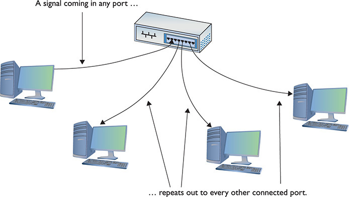
Figure 3-2 Ethernet hub
10BaseT
In 1990, the IEEE 802.3 committee created a version of Ethernet called 10BaseT that rapidly became the most popular network technology in the world, replacing competing and now long-gone competitors with names like Token Ring and AppleTalk. The classic 10BaseT network consisted of two or more computers connected to a central hub. The NICs connected with wires as specified by the 802.3 committee.
The name 10BaseT follows roughly the same naming convention used for earlier Ethernet cabling systems. The number 10 refers to the speed: 10 Mbps. The word Base refers to the signaling type: baseband. (Baseband means that the cable only carries one type of signal. Contrast this with broadband—as in cable television—where the cable carries multiple signals or channels.) The letter T refers to the type of cable used: twisted-pair. 10BaseT used unshielded twisted-pair (UTP) cabling.
UTP
Officially, 10BaseT required the use of Cat 3 (or higher), two-pair, unshielded twisted-pair (UTP) cable. One pair of wires sent data to the hub while the other pair received data from the hub. Even though 10BaseT only required two-pair cabling, everyone installed four-pair cabling to connect devices to the hub as insurance against the possible requirements of newer types of networking (Figure 3-3). Not surprisingly, this came in handy very soon. See Chapter 4, “Modern Ethernet,” for more details.
Figure 3-3 A typical fourpair Cat 5e unshielded twisted-pair cable
Most UTP cables (then and now) come with stranded Kevlar fibers to give the cable added strength, which, in turn, enables installers to pull on the cable without excessive risk of literally ripping it apart.
10BaseT also introduced the networking world to the RJ-45 connector (Figure 3-4). Each pin on the RJ-45 connects to a single wire inside the cable; this enables devices to put voltage on the individual wires within the cable. The pins on the RJ-45 are numbered from 1 to 8, as shown in Figure 3-5.

Figure 3-4 Two views of an RJ-45 connector

Figure 3-5 The pins on an RJ-45 connector are numbered 1 through 8.
The 10BaseT standard designates some of these numbered wires for specific purposes. As mentioned earlier, although the cable has four pairs, 10BaseT used only two of the pairs. 10BaseT devices used pins 1 and 2 to send data, and pins 3 and 6 to receive data. Even though one pair of wires sent data and another received data, a 10BaseT device connected to a hub could not send and receive simultaneously. See “CSMA/CD” later in this chapter for details about collisions and using a shared bus.
NICs that can communicate in only one direction at a time run in half-duplex mode. Later advances (as you’ll see shortly) enabled NICs to send and receive at the same time, thus running in full-duplex mode.
An RJ-45 connector is usually called a crimp, and the act (some folks call it an art) of installing a crimp onto the end of a piece of UTP cable is called crimping. The tool used to secure a crimp onto the end of a cable is a crimper. Each wire inside a UTP cable must connect to the proper pin inside the crimp. Manufacturers color-code each wire within a piece of four-pair UTP to assist in properly matching the ends. Each pair of wires consists of a solid-colored wire and a striped wire: blue/blue-white, orange/orange-white, brown/brown-white, and green/green-white (Figure 3-6).

Figure 3-6 Color-coded pairs (note the alternating solid and striped wires)
NOTE As noted in Chapter 2, the real name for RJ-45 is 8 position 8 contact (8P8C) modular plug. The term RJ-45 is so prevalent, however, that nobody but the nerdiest of nerds calls it by its real name. Stick to RJ-45.
The Telecommunications Industry Association/Electronics Industries Alliance (TIA/EIA) defines the industry standard for correct crimping of four-pair UTP. You’ll find two standards mentioned on the CompTIA Network+ exam: TIA/EIA 568A and TIA/EIA 568B. (CompTIA uses lower-case letters in the objectives, at least as we go to press—568a and 568b—though the industry uses upper-case.) Figure 3-7 shows the TIA/EIA 568A and TIA/EIA 568B color-code standards. Note that the wire pairs used by 10BaseT (1 and 2, 3 and 6) come from the same color pairs (green/green-white and orange/orange-white). Following an established color-code scheme, such as TIA/EIA 568A, ensures that the wires match up correctly at each end of the cable.
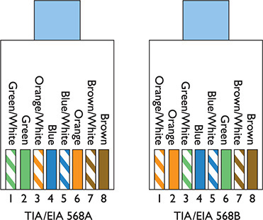
Figure 3-7 The TIA/EIA 568A and 568B standards
EXAM TIP TIA/EIA 568C, the current standard, includes the same wiring standards as TIA/EIA 568A and TIA/EIA 568B. It’s all just wrapped up in a slightly different name: ANSI/TIA-568-C. When the EIA left the planet in 2011, the names of the standards changed. CompTIA continues to use the older names on exams.
The ability to make your own Ethernet cables is a real plus for a network tech. With a reel of Cat 5e, a bag of RJ-45 connectors, a moderate investment in a crimping tool, and a little practice, you can kiss those mass-produced cables goodbye! You can make cables to your own length specifications, replace broken RJ-45 connectors that would otherwise mean tossing an entire cable—and, in the process, save your company or clients time and money.
EXAM TIP An easy trick to remembering the difference between 568A and 568B is the word “GO.” The green and orange pairs are swapped between 568A and 568B, whereas the blue and brown pairs stay in the same place!
For the CompTIA Network+ exam, you will be tested on the TIA/EIA 568a or 568b color codes. Memorize them. You’ll see the standards listed as EIA/TIA 568A, TIA/EIA568A, T568A, or just 568A. Know the A and B and you’ll be fine.
10BaseT Limits and Specifications
Like any other Ethernet standard, 10BaseT had limitations, both on cable distance and on the number of computers. The key distance limitation for 10BaseT was the distance between the hub and the computer. The twisted-pair cable connecting a computer to the hub could not exceed 100 meters in length. A 10BaseT hub could connect no more than 1024 computers, although that limitation rarely came into play. It made no sense for vendors to build hubs that large—or more to the point, that expensive.
10BaseT Summary
• Speed 10 Mbps
• Signal type Baseband
• Distance 100 meters between the hub and the node
• Node limit No more than 1024 nodes per hub
• Topology Star-bus topology: physical star, logical bus
• Cable type Cat 3 or better UTP cabling with RJ-45 connectors

SIM Check out the Chapter 3 Challenge! sim “T-568B” here: http://totalsem.com/007 It’s a great tool for getting the colors set in your head.
10BaseFL
Just a few years after the introduction of 10BaseT, a fiber-optic version, called 10BaseFL, appeared. As you know from the previous chapter, fiber-optic cabling transmits data packets using pulses of light instead of using electrical current. Using light instead of electricity addresses the three key weaknesses of copper cabling. First, optical signals can travel much farther. The maximum length for a 10BaseFL cable was up to 2 kilometers, depending on how you configured it. Second, fiber-optic cable is immune to electrical interference, making it an ideal choice for high-interference environments. Third, the cable is much more difficult to tap into, making fiber a good choice for environments with security concerns. 10BaseFL used multimode fiber-optic and employed either an SC or an ST connector.
NOTE 10BaseFL is often simply called “10BaseF.”
Figure 3-8 shows a typical 10BaseFL card. Note that it uses two fiber connectors—one to send and one to receive. All fiber-optic networks use at least two fiber-optic cables. Although 10BaseFL enjoyed some popularity for a number of years, most networks today are using the same fiber-optic cabling to run far faster network technologies.
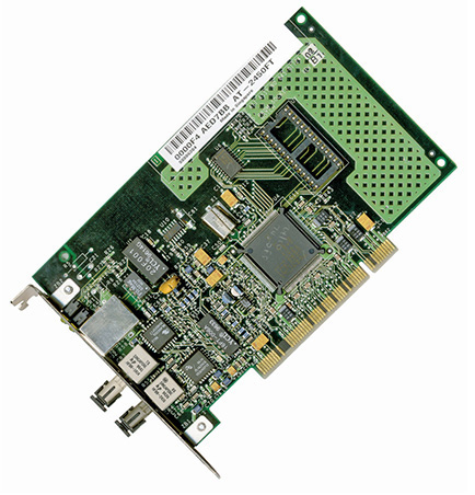
Figure 3-8 Typical 10BaseFL card
10BaseFL Summary
• Speed 10 Mbps
• Signal type Baseband
• Distance 2000 meters between the hub and the node
• Node limit No more than 1024 nodes per hub
• Topology Star-bus topology: physical star, logical bus
• Cable type Multimode fiber-optic cabling with ST or SC connectors
So far you’ve seen two different flavors of star-bus Ethernet, 10BaseT and 10BaseFL. Even though these used different cabling and hubs, the actual packets were still Ethernet frames. As a result, interconnecting flavors of Ethernet were (and still are) common. Because 10BaseT and 10BaseFL used different types of cable, you could use a media converter (Figure 3-9) to interconnect different Ethernet types.

Figure 3-9 Typical copper-to-fiber Ethernet media converter (photo courtesy of TRENDnet)
CSMA/CD
One of the issues with bus communication is that devices essentially share the same cable. This applies to pure bus networks and hybrid star-bus networks as well. The NICs need some way to determine which machine should send data at which time. Ethernet designers came up with a clever way to handle the issue of potential collisions.
Ethernet networks use a system called carrier sense multiple access/collision detection (CSMA/CD) to determine which computer should use a shared cable at a given moment. Carrier sense means that each node using the network examines the cable before sending a data frame (Figure 3-10). If another machine is using the network, the node detects traffic on the segment, waits a few milliseconds, and then rechecks. If it detects no traffic—the more common term is to say the cable is “free”—the node sends out its frame.

Figure 3-10 No one else is talking—send the frame!
EXAM TIP CSMA/CD is a network access method that maps to the IEEE 802.3 standard for Ethernet networks.
Multiple access means that all machines have equal access to the wire. If the line is free, any Ethernet node may begin sending a frame. From Ethernet’s point of view, it doesn’t matter what function the node is performing: it could be a desktop system running Windows 10 or a file server running Windows Server or Linux. As far as Ethernet is concerned, a node is a node is a node and access to the cable is assigned strictly on a first-come, first-served basis.
So what happens if two machines, both listening to the cable, simultaneously decide that it is free and try to send a frame? A collision occurs, and both of the transmissions are lost (Figure 3-11). A collision resembles the effect of two people talking at the same time: the listener hears a mixture of two voices and can’t understand either one.

Figure 3-11 Collision!
When two NICs send at the same time, they’ll sense the overlapping signals, and immediately know that a collision has occurred. When they detect a collision, both nodes stop transmitting.
They then each generate a random number to determine how long to wait before trying again. If you imagine that each machine rolls its magic electronic dice and waits for that number of seconds, you wouldn’t be too far from the truth, except that the amount of time an Ethernet node waits to retransmit is much shorter than one second (Figure 3-12). Whichever node generates the lowest random number begins its retransmission first, winning the competition to use the wire. The losing node then sees traffic on the wire and waits for the wire to be free again before attempting to retransmit its data.

Figure 3-12 Rolling for timing
Collisions were a normal part of the operation of early Ethernet networks, because every device shared a bus. A group of nodes that have the capability of sending frames at the same time as each other, resulting in collisions, is called a collision domain. Better technology today makes collisions very rare.
Enhancing and Extending Ethernet Networks
While plain-vanilla 10BaseT Ethernet performed well enough for first-generation networks (which did little more than basic file and print sharing), by the early 1990s networks used more-demanding applications, such as Lotus Notes, SAP business management software, and Microsoft Exchange, which quickly saturated a 10BaseT network. Fortunately, those crazy kids over at the IEEE kept expanding the standard, giving the network tech in the trenches a new tool that provided additional bandwidth—the switch.
Additionally, more companies and organizations adopted Ethernet, leading to a demand for larger networks, both geographically and in the number of nodes that could interconnect. Hubs were cranky and creaky; switches brought much better scalability.
The Trouble with Hubs
A classic 10BaseT network with a hub could only have one message on the wire at any time. When two computers sent at the same time, the hub dutifully repeated both signals. The nodes recognized the collision and, following the rules of CSMA/CD, attempted to resend. Add in enough computers and the number of collisions increased, lowering the effective transmission speed for the whole network. A busy network became a slow network because all the computers shared the same collision domain.
EXAM TIP Adding another hub or two to an early Ethernet network enabled you to add more devices, but also compounded the problem with collisions. In such a scenario, you could connect networks using a bridge. A bridge acted like a repeater to connect two networks, but then went a step further—filtering and forwarding traffic between those segments based on the MAC addresses of the computers on those segments. This placement between two segments preserved bandwidth, making larger Ethernet networks possible. You’ll see the term “bridge” applied to modern devices, primarily in wireless networking. The interconnectedness of network segments is similar, but the devices are fundamentally different. See Chapter 14 for the scoop on wireless.
Switches to the Rescue
An Ethernet switch looks like a hub, because all nodes plug into it (Figure 3-13). But switches don’t function like hubs inside. Switches come with extra smarts that enable them to take advantage of MAC addresses, effectively creating point-to-point connections between two conversing computers. This gives every conversation between two computers the full bandwidth of the network.
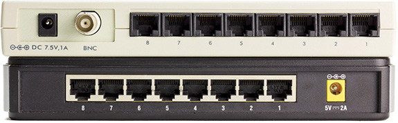
Figure 3-13 Hub (top) and switch (bottom) comparison
To see a switch in action, check out Figure 3-14. When you first turn on a switch, it acts like a hub, passing all incoming frames right back out to all the other ports. As it forwards all frames, however, the switch copies the source MAC addresses and quickly creates a table of the MAC addresses of each connected computer, called a source address table (SAT).

Figure 3-14 A switch tracking MAC addresses
EXAM TIP One classic difference between a hub and a switch is in the repeating of frames during normal use. Although it’s true that switches initially forward all frames, they filter by MAC address in regular use. Hubs never learned and always forwarded all frames.
As soon as this table is created, the switch begins to do something amazing. When a computer sends a frame into the switch destined for another computer on the same switch, the switch acts like a telephone operator, creating an on-the-fly connection between the two devices. While these two devices communicate, it’s as though they are the only two computers on the network. Figure 3-15 shows this in action. Because the switch handles each conversation individually, each conversation runs at the full network speed.
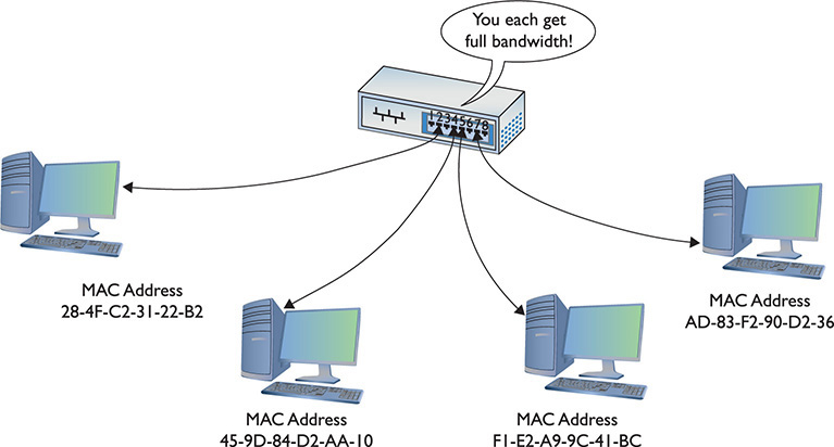
Figure 3-15 A switch making two separate connections
Each port on a switch is in its own collision domain, plus the switch can buffer incoming frames. That means that two nodes connected to the switch can send data at the same time and the switch will handle it without any collision.
NOTE Because a switch filters traffic on MAC addresses (and MAC addresses run at Layer 2 of the OSI seven-layer model), they are sometimes called Layer 2 switches.
Unicast messages always go only to the intended recipient when you use a switch. The switch will send all broadcast messages to all the ports (except the port on which the frame originated). You’ll commonly hear a switched network called a broadcast domain to contrast it to the ancient hub-based networks with their collision domains.
Connecting Ethernet Segments
Sometimes, one switch is just not enough. Once an organization uses every port on its existing switch, adding more nodes requires adding switches. Even fault tolerance can motivate an organization to add more switches. If every node on the network connects to the same switch, that switch becomes a single point of failure—if it fails, everybody drops off the network. You can connect switches in two ways: via an uplink port or a crossover cable.
Uplink Ports
Uplink ports enable you to connect two switches using a straight-through cable. They’re clearly marked on older switches, as shown in Figure 3-16. To connect two switches, insert one end of a cable in the uplink port and the other end of the cable in any one of the regular ports on the other switch.

Figure 3-16 Typical uplink port
Modern switches do not have a dedicated uplink port, but instead auto-sense when another switch is plugged in. You can plug into any port.
Crossover Cables
Switches can also connect to each other via special twisted-pair cables called crossover cables. A crossover cable reverses the sending and receiving pairs on one end of the cable. One end of the cable is wired according to the TIA/EIA 568A standard, whereas the other end is wired according to the TIA/EIA 568B standard (Figure 3-17). With the sending and receiving pairs reversed, the switches can hear each other; hence the need for two standards for connecting RJ-45 jacks to UTP cables.

Figure 3-17 A crossover cable reverses the sending and receiving pairs.
A crossover cable connects to a regular port on each switch. Modern switches with auto-sensing ports don’t require a crossover cable.
In a pinch, you can use a crossover cable to connect two computers together using Ethernet NICs with no switch between them at all. This is handy for quickie connections, although not used much anymore because we mostly go wireless now.
Spanning Tree Protocol
Because you can connect switches together in any fashion, you can create redundant connections in a network. These are called bridging loops or switching loops (Figure 3-18).

Figure 3-18 A bridging loop
EXAM TIP The CompTIA Network+ exam refers to STP, BPDU guard, and root guard as mitigation techniques. That’s a fancy term for “making bad things not as destructive.”
In the early days of switches, making a bridging loop in a network setup would bring the network crashing down. A frame could get caught in the loop, so to speak, and not reach its destination.
The Ethernet standards body adopted the Spanning Tree Protocol (STP) to eliminate the problem of accidental bridging loops. For decades, switches have had STP enabled by default, and can detect potential loops before they happen. Using special STP frames known as bridge protocol data units (BPDUs), switches communicate with other switches to prevent loops from happening in the first place.
Configuration BPDUs establish the topology, where one switch is elected root bridge and acts as the center of the STP universe. Each switch then uses the root bridge as a reference point to maintain a loop-free topology. There will be redundant links, for fault tolerance, that would ordinarily cause a bridging loop, but certain ports will be placed in a “blocking” state and will not send or receive data frames. Ports in the blocking state will still hear the configuration BPDUs, which are sourced by the root bridge and forwarded downstream to the other switches every 2 seconds.
If a link or device goes down, STP springs into action with another type of BPDU, called a topology change notification (TCN) BPDU, that enables the switches to rework themselves around the failed interface or device. The blocked ports, listening to the BPDUs, will realize they’re needed and eventually move to a forwarding state.
Administrators can manually change STP settings for a switch. A switch port directly connected to a PC, for example, should never participate in STP, and could be configured with a setting called PortFast that enables the interface to come up right away, without the normal latency introduced by STP. Another reason to configure switch ports with PortFast is to prevent TCN BPDUs being sent out of that switch every time a PC is powered on and off, which has severe side effects, like causing all switches to flush their source address table, and relearn MAC addresses.
BPDU guard will move a port configured with PortFast into an errdisable state (i.e., error occurred, disabled) if a BPDU is received on that port. This requires an administrator to manually bring the port back up.
Ports configured with PortFast should never receive a BPDU, and if they do, it could start a bridging loop. Another mechanism, root guard, will move a port into a root-inconsistent state if BPDUs coming from a certain direction indicate another switch is trying to become the root bridge. The root-inconsistent port will automatically return to its forwarding state once these BPDUs stop. This helps define locations where the root bridge should never be located.
The original Spanning Tree Protocol, introduced by IEEE as 802.1d, was replaced a long time ago (2001) by the Rapid Spanning Tree Protocol (RSTP), 802.1w. RSTP offers significantly faster convergence time following some kind of network change. STP could take up to 50 seconds to get back to a steady state, for example, whereas an RSTP network could return to convergence in 6 seconds.
Troubleshooting Switches
The simple switches described in this chapter generally function flawlessly for years without any need for a tech to do more than wipe dust off the top. Very occasionally you’ll run into a switch that has problems. These problems fall into two categories:
• Obvious physical damage
• Dead ports
Diagnosing any of these problems follows a similar pattern. First, you recognize that a switch might have problems because a device you’ve plugged in can’t connect to the network. Second, you examine the switch for obvious damage. Third, you look for link lights. If they’re not flashing, try a different port. Fourth, you look at your cables. If anything looks bent, broken, or stepped on, you should replace it. A bad cable or improper cable type can lead to problems that point to a “failed” switch when the true culprit is really the cable. Finally, you use the tried and true method of replacing the switch or the cable with a known-good device.
NOTE When we get to modern higher-end switches in Chapter 11, “Advanced Networking Devices,” you’ll need to follow other procedures to do proper diagnostic work. We’ll get there soon enough!
Chapter Review
Questions
1. Ethernet hubs take an incoming packet and _______________ it out to the other connected ports.
A. amplify
B. repeat
C. filter
D. distort
2. What is appended to the beginning of the Ethernet frame?
A. MAC address
B. Length
C. Preamble
D. CRC
3. What type of bus does 10BaseT use?
A. Bus
B. Ring
C. Star bus
D. Bus ring
4. What is the maximum distance that can separate a 10BaseT node from its hub?
A. 50 meters
B. 100 meters
C. 185 meters
D. 200 meters
5. When used for Ethernet, unshielded twisted pair uses what type of connector?
A. RG-58
B. RJ-45
C. RJ-11
D. RS-232
6. What is the maximum number of nodes that can be connected to a 10BaseT hub?
A. 1024
B. 500
C. 100
D. 185
7. Which of the following is not true of crossover cables?
A. They are a type of twisted-pair cabling.
B. They reverse the sending and receiving wire pairs.
C. They are used to connect hubs.
D. Both ends of a crossover cable are wired according to the TIA/EIA 568B standard.
8. Which of the following connectors are used by 10BaseFL cable? (Select two.)
A. SC
B. RJ-45
C. RJ-11
D. ST
9. Which networking devices can use the Spanning Tree Protocol (STP)?
A. Hubs
B. Media converters
C. UTP cables
D. Switches
10. What device directs packets based on MAC addresses?
A. Router
B. Hub
C. Repeater
D. Switch
Answers
1. B. Hubs are nothing more than multiport repeaters.
2. C. Appended to the front of the Ethernet frame is the preamble.
3. C. 10BaseT uses a star-bus topology.
4. B. The maximum distance between a 10BaseT node and its hub is 100 meters.
5. B. UTP cable uses an RJ-45 connector when used for Ethernet. RG-58 is the type of coaxial cable used with 10Base2. RJ-11 is the standard four-wire connector used for regular phone lines. RS-232 is a standard for serial connectors.
6. A. A 10BaseT hub can connect no more than 1024 nodes (computers).
7. D. One end of a crossover cable is wired according to the TIA/EIA 568B standard; the other is wired according to the TIA/EIA 568A standard. This is what crosses the wire pairs and enables two hubs to communicate without colliding.
8. A, D. 10BaseFL uses two types of fiber-optic connectors called SC and ST connectors.
9. D. The Spanning Tree Protocol is unique to switches.
10. D. A switch uses MAC addresses to direct traffic only to the appropriate recipient.