CHAPTER 13
Remote Connectivity
The CompTIA Network+ certification exam expects you to know how to
• 1.1 Explain the purposes and uses of ports and protocols
• 1.3 Explain the concepts and characteristics of routing and switching
• 1.4 Given a scenario, configure the appropriate IP addressing components
• 1.5 Compare and contrast the characteristics of network topologies, types and technologies
• 2.1 Given a scenario, deploy the appropriate cabling solution
• 2.2 Given a scenario, determine the appropriate placement of networking devices on a network and install/configure them
• 2.5 Compare and contrast WAN technologies
• 3.4 Given a scenario, use remote access methods
To achieve these goals, you must be able to
• Describe WAN telephony technologies, such as SONET, T1, and T3
• Compare last-mile connections for connecting homes and businesses to the Internet
• Discuss and implement various remote access connection methods
• Troubleshoot various WAN scenarios
Computers connect to other computers locally in a local area network (LAN)—you’ve read about LAN connections throughout this book—and remotely through a number of different methods. Interconnecting computers over distances, especially when the connections cross borders or jurisdictions, creates a wide area network (WAN), though the term is pretty flexible. This chapter takes both an historical and a modern look at ways to interconnect a local computer or network with distant computers, what’s called remote connectivity.
Historical/Conceptual
Remote connections have been around for a long time. Before the Internet, network users and developers created ways to take a single system or network and connect it to another faraway system or network. This wasn’t the Internet! These were private interconnections of private networks. These connections were very expensive and, compared to today’s options, pretty slow.
As the Internet developed, most of the same technologies used to make the earlier private remote connections became the way the Internet itself interconnects. Before the Internet was popular, many organizations used dedicated lines, called T1 lines (discussed in more detail later in this chapter), to connect far-flung offices. T1 is a dying technology and rarely used today.
This chapter shows you all the ways you can make remote connections. You’ll see every type of remote connection currently in popular use, from good-old telephone lines to advanced fiber-optic carriers, and even satellites. There are so many ways to make remote connections that this chapter is broken into four parts. The first part, “Telephony and Beyond,” gives you a tour of the technologies that originally existed for long-distance voice connections that now also support data. The next part, “The Last Mile,” goes into how we as individual users connect to those long-distance technologies and demonstrates how wireless technologies come into play in remote connectivity. Third, “Using Remote Access” shows you the many different ways to use these connections to connect to another, faraway computer. The chapter finishes with a section on troubleshooting various WAN scenarios. Let’s get started!
Telephony and Beyond
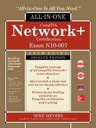
We’ve already discussed the Tier 1 ISPs of the Internet, but let’s look at them once again in a different way. Describing the Tier 1 Internet is always an interesting topic. Those of us in the instruction business invariably start this description by drawing a picture of the United States and then adding lines connecting big cities, as shown in Figure 13-1.
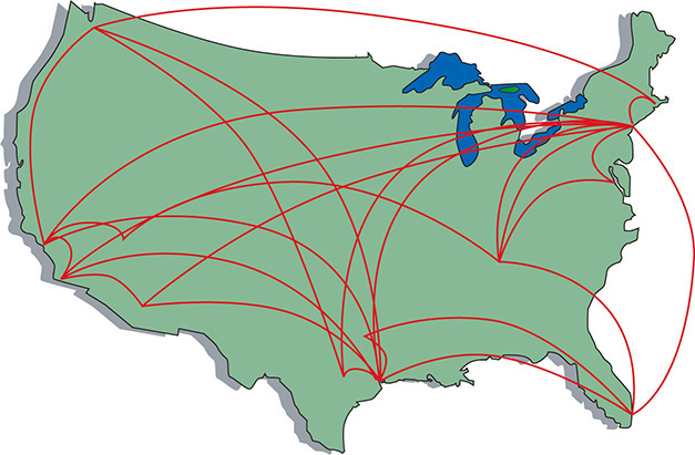
Figure 13-1 The Tier 1 Internet
But what are these lines and where did they come from? If the Internet is just a big TCP/IP network, wouldn’t these lines be Ethernet connections? Maybe copper, maybe fiber, but surely they’re Ethernet? Well, traditionally they’re not. The vast majority of the long-distance connections that make up the Internet use a unique type of signal called SONET. SONET was originally designed to handle special heavy-duty circuits with names like T1. Never heard of SONET or T1? Don’t worry—you’re about to learn quite a bit.

NOTE Even as you read this, more and more of the Internet interconnections are moving toward Gigabit and 10-Gigabit Ethernet. Telephone technologies, however, continue to dominate.
Most of the connections that make up the high-speed backbone of the Internet use technologies designed at least 20 years ago to support telephone calls. We’re not talking about your cool, cell phone–type calls here, but rather the old-school, wire-runs-up-to-the-house, telephone-connected-to-a-phone-jack connections. (See “Public Switched Telephone Network” later in this chapter for more on this subject.) If you want to understand how the Internet connects, you have to go way back to the 1970s and 1980s, before the Internet really took off, and learn how the U.S. telephone system developed to support networks.
The Dawn of Long Distance
Have you ever watched one of those old-time movies in which someone makes a phone call by picking up the phone and saying, “Operator, get me Mohawk 4, 3-8-2-5!” Suddenly, the scene changes to some person sitting at a switchboard like the one shown in Figure 13-2.

Figure 13-2 Old-time telephone operator (photo courtesy of the Richardson Historical and Genealogical Society)
This was the telephone operator. The telephone operator made a physical link between your phone and the other phone, making your connection. The switchboard acted as a circuit switch, where plugging in the two wires created a physical circuit between the two phones. This worked pretty well in the first few years of telephones, but it quickly became a problem as more and more phone lines began to fill the skies overhead (Figure 13-3).

Figure 13-3 Now that’s a lot of telephone lines!
These first generations of long-distance telephone systems (think 1930s here) used analog signals, because that was how your telephone worked—the higher and lower the pitch of your voice, the lower or greater the voltage. If you graphed out a voice signal, it looked something like Figure 13-4. This type of transmission had issues, however, because analog signals over long distances, even if you amplified them, lost sound quality very quickly.
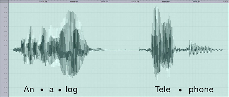
Figure 13-4 Another problem of early long-distance telephone systems
The first problem to take care of was the number of telephone wires. Individual wires were slowly replaced with special boxes called multiplexers. A multiplexer took a circuit and combined it with a few hundred other circuits into a single complex circuit on one wire. A demultiplexer (devices were both multiplexers and demultiplexers) on the other end of the connection split the individual connections back out (Figure 13-5).

Figure 13-5 Multiplexers combine multiple circuits.

EXAM TIP The various multiplexing and demultiplexing technologies and protocols, both analog and digital, are collectively referred to as modulation techniques, a term you might see on the CompTIA network+ exam. Modulation more technically means converting a digital signal to analog or pushing an analog signal to a higher frequency. Pay attention to the wording of any exam questions on modulation.
Over time, the entire United States was divided into hundreds, eventually thousands, of local exchanges. Local exchanges were a defined grouping of individual phone circuits served by a single multiplexer (calls within the exchange were handled first by human operators who were replaced, eventually, with dial tones and special switches that interpreted your pulses or tones for a number). One or more exchanges were (and still are) housed in a physical building called a central office (Figure 13-6) where individual voice circuits all came together. Local calls were still manually connected (although automatic exchanges began to appear in earnest by the 1950s, after which many operators lost their jobs), but any connection between exchanges was carried over these special multiplexed trunk lines. Figure 13-7 shows a very stylized example of how this worked.

Figure 13-6 A central office building

Figure 13-7 Interconnected central offices
These old-style trunk lines were fascinating technology. How did they put a bunch of voice calls on a single piece of cable, yet still somehow keep them separate? To understand the trick, you need to appreciate a little bit about frequency. A typical telephone only detects a fairly limited frequency range—from around 350 Hz to around 4000 Hz. This range covers enough of the human speech range to make a decent phone call. As the individual calls came into the multiplexer, it added a certain frequency multiplier to each call, keeping every separate call in its own unique frequency range (Figure 13-8). This process is called frequency division multiplexing (FDM).

Figure 13-8 Multiplexed FDM
This analog network still required a physical connection from one phone to the other, even if those phones were on opposite sides of the country. Long distance used a series of trunk lines, and at each intersection of those lines an operator had to connect the calls. When you physically connect two phones together on one circuit, you are using something called circuit switching. As you might imagine, circuit switching isn’t that great for long distance, but it’s your only option when you use analog.
NOTE The long-distance lines used for voice calls are the same ones that carry our Internet data. There is no difference as far as the carriers are concerned.
This analog system worked pretty well through the 1930s to the 1950s, but telephones became so common and demand so heavy that the United States needed a new system to handle the load. The folks developing this new system realized that they had to dump analog and replace it with a digital system—sowing the seeds for the remote connections that eventually became the Internet.
Digital data transmits much easier over long distances than analog data because you can use repeaters. (You cannot use repeaters on analog signals.) A repeater is not an amplifier. An amplifier just increases the voltage and includes all the pops and hisses created by all kinds of interferences. A repeater takes the entire digital signal and re-creates it out the other end (Figure 13-9).

Figure 13-9 Repeater vs. amplifier
The downside to adopting a digital system was that the entire telephone system was analog: every telephone, every switch, every multiplexer. The task of converting the entire analog voice system to digital was a massive undertaking. Luckily, virtually the entire U.S. phone system at that time was a monopoly run by a company called AT&T. A single company could make all of its own decisions and its own standards—one of the few times in history where a monopoly was probably a good thing. The AT&T folks had a choice here: completely revamp the entire U.S. phone system, including replacing every single telephone in the United States, or just make the trunk lines digital and let the central offices convert from analog to digital. They chose the latter.
Even today, a classic telephone line in your home or small office uses analog signals—the rest of the entire telephone system is digital. The telecommunications industry calls the connection from a central office to individual users the last mile. The telephone company’s decision to keep the last mile analog has had serious repercussions that still challenge us even in the 21st century (Figure 13-10).

Figure 13-10 Analog and digital
NOTE Attempts were made to convert the entire telephone system, including your telephones, to digital, but these technologies never took off (except in a few niches). See “ISDN” later in this chapter.
Test Specific
Digital Telephony
You’ll find digital telephony easy to understand, because most of the aspects you’ve already learned about computer networking work roughly the same way in a telephone network. In fact, most of the concepts that created computer networking came from the telephone industry. For example, the telephone industry was the first technology to adopt heavily the idea of digital packets. It was the first to do what is now called switching. Heck, the telephone industry even made the first working topologies! Let’s take advantage of what you already know about how networks work to learn about how the telephone industry invented the idea of digital networks.
When you learned about networks in the first few chapters of this book, you learned about cabling, frame types, speeds, switching, and so on. All of these are important for computer networks. Well, let’s do it again (in a much simpler format) to see the cabling, frame types, speed, and switching used in telephone systems. Don’t worry—unlike computer networks, in which a certain type of cable might run different types of frames at different speeds, most of the remote connections used in the telephony world tend to have one type of cable that only runs one type of frame at one speed.
Let’s begin with the most basic data chunk you get in the telephone world: DS0.
It All Starts with DS0
When AT&T decided to go digital, it knew all phone calls had to be broken into a digital sample. AT&T determined that if it took an analog signal of a human voice and converted it into 8-bit chunks 8000 times a second, it would be good enough to re-create the sound later. Figure 13-11 shows an example of the analog human voice seen earlier being converted into a digital sample.

Figure 13-11 Analog to digital
NOTE A modulator takes a digital signal and converts it into an analog signal. A demodulator takes an analog signal and converts it into a digital signal. You call a device that does both a modulator-demodulator, better known as a modem. Because many people refer to modern DSL and cable boxes as “modems,” you’ll hear the term analog modem to describe the old-style analog-to-digital devices. See “The Last Mile” later in this chapter for the scoop on all the ways to connect today.
Converting analog sound into 8-bit chunks 8000 times a second creates a data stream (called a digital signal) of 8 × 8000 = 64 kilobits per second (Kbps). This digital signal rate, known as DS0, makes up the simplest data stream (and the slowest rate) of the digital part of the telephone system. Each analog voice call gets converted into a DS0 signal at the telephone company’s central office. From there they are multiplexed into larger circuits.
Now that we have our voice calls converted to digital data, we need to get them to the right telephone. First, we need network technologies to handle the cabling, frames, and speed. Second, we need to come up with a method to switch the digital voice calls across a network. To handle the former, we need to define the types of interconnections, with names like T1 and OC-3. To handle the latter, we no longer connect via multiplexed circuit switching, as we did back with analog, but rather are now switching packets. I’ll show you what I mean as I discuss the digital lines in use today.
Copper Carriers: T1 and T3
The first (and still popular) digital trunk carriers used by the telephone industry are called T-carriers. There are a number of different versions of T-carriers and the CompTIA Network+ exam expects you to know something about them. Let’s begin with the most common and most basic, the venerable T-carrier level 1 (T1).
NOTE What does the “T” stand for in T1? The most common explanation is “trunk-level,” because T1 and later T-carriers functioned as trunk lines. The more definitive explanation is “terrestrial,” so named in the early 1960s to differentiate between ground-based and space-based communications when the first satellites went into orbit.
T1 has several meanings. First, it refers to a digital networking technology called a T1 connection. Second, the term T1 line refers to the specific, shielded, two-pair cabling that connects the two ends of a T1 connection (Figure 13-12). Two wires are for sending data and two wires are for receiving data. The cable ends with a modular jack, called an RJ-48C, that looks a lot like the RJ-45 connector you’re used to seeing with Ethernet cables.
Figure 13-12 T1 line
At either termination of a T1 line, you’ll find an unassuming box called a Channel Service Unit/Digital Service Unit (CSU/DSU). The CSU/DSU has a second connection that goes from the phone company (where the boxes reside) to a customer’s equipment (usually a router). A T1 connection is point-to-point—you cannot have more than two CSU/DSUs on a single T1 line.
EXAM TIP You can connect two CSU/DSU boxes together directly by using a T1 crossover cable. Like the UTP crossover cables you’ve seen previously in the book, the T1 crossover cable simply reverses the send/receive pairs on one end of the cable. You’ll only see this in use to connect older routers together. The CSU/DSU connections provide convenient link points.
T1 uses a special signaling method called a digital signal 1 (DS1).
DS1 uses a relatively primitive frame—the frame doesn’t need to be complex because with point-to-point no addressing is necessary. Each DS1 frame has 25 pieces: a framing bit and 24 channels. Each DS1 channel holds a single 8-bit DS0 data sample. The framing bit and data channels combine to make 193 bits per DS1 frame. These frames are transmitted 8000 times/sec, making a total throughput of 1.544 Mbps (Figure 13-13). DS1 defines, therefore, a data transfer speed of 1.544 Mbps, split into 24 64-Kbps DS0 channels. The process of having frames that carry a portion of every channel in every frame sent on a regular interval is called time division multiplexing (TDM).

Figure 13-13 DS1 frame
NOTE Each 64-Kbps channel in a DS1 signal is a DS0.
When discussing T1 technology in class, I like to use an analogy of a conveyor belt in a milk-bottling factory. At regular intervals, big crates with 24 bottles come rolling down the belt. When they reach the filling machine, the bottles get filled with milk, and the crate keeps rolling down to the other end where two machines take over: the labeling and sorting machines. The labeling machine plucks out the bottles and applies a label to each, appropriate to the contents. The sorting machine sorts the bottles into cases of each type.
This is pretty simple if the filling machine uses only one type of milk. All 24 bottles fill with whole milk; all are labeled as whole milk; and all go into the case marked “Whole Milk.” Once enough full bottles of milk arrive, the case gets completed, and you have a product.
That’s pretty much how an Ethernet frame works, right? The whole frame encapsulates a single set of data, such as an IP packet that, in turn, encapsulates a single type of TCP segment, UDP datagram, or ICMP packet. It generally takes multiple frames to get the data to the recipient, where the frames are removed, the IP packet is removed, and the segment or datagram gets put together to make the data transfer complete.
The cool thing about the DS1 frame, though, is that you don’t have to use the whole frame for a single set of data. With the right CSU/DSU at either end, you can specify which channels go with a specific thread of data. Sloshing back into the analogy, the milk company produces four types of milk: whole milk, low-fat milk, chocolate milk, and strawberry milk. The strawberry milk is seasonal; the whole milk sells the most, followed by chocolate, and then low fat.
To accommodate the different products, the factory master might designate channels 1–10 for whole milk, 11–18 for chocolate milk, 19–22 for low-fat milk, and 23–24 for strawberry. Now the labeling and sorting machines are going to have to work for a living! When a crate reaches the filling machine, the bottles get filled with the various types of milk, and then the crate trundles on down the belt. The labeling machine knows the numbering system, so it labels bottles 1–10 as whole milk, 11–18 as chocolate, and so on. The sorting machine also knows the system and has four cases at hand, one for each product. As the bottles arrive, it places them into the appropriate cases. Note that the cases will fill at different rates of speed. The strawberry milk case will take longer to fill, especially compared to the whole milk case, because only two channels in each crate carry strawberry.
What happens if the cows temporarily stop producing chocolate milk? Will the whole factory need to be reordered so the filling machine’s eight chocolate dispensers can dispense some other kind of milk? Not in this factory. The crates continue to roll down the conveyor belt at regular intervals. The filling machine fills the bottles in channels 1–10 with whole milk, leaves the bottles in channels 11–18 empty, and puts low fat and strawberry in channels 19–22 and 23–24, respectively.
DS1/T1 work the same way. The frame just keeps jetting down the line, even if some of the channels contain no data. The CSU/DSU at the other end collects the data streams and keeps them separate. To paraphrase the immortal words of Professor Egon, “Never cross the streams.” (You have seen Ghostbusters, right?) Otherwise you’d lose data.
NOTE People rarely use the term “DS1.” Because T1 lines only carry DS1 signals, you usually just say T1 when describing the signal, even though the term DS1 is more accurate.
To bring the milk bottling–factory analogy completely into the realm of networking and T1 connections, keep in mind that two conveyor belts are running in opposite directions. Milk flows in; milk flows out. You can both send and receive on T1 connections.
A T1 line is a dedicated phone connection that you lease, usually on a monthly basis, from the telephone company. It has no telephone number, and it’s always connected. An entire T1 bundle is expensive (and obsolete), so some telephone companies let you buy just some of these individual channels, a practice known as fractional T1 access.
A T3 line supports a data rate of about 45 Mbps on a dedicated telephone connection. It consists of 672 individual DS0 channels. T3 lines (sometimes referred to as DS3 lines) are mainly used by regional telephone companies and ISPs connecting to the Internet.
Similar to the North American T1 line, E-carrier level 1 (E1) is the European format for digital transmission. An E1 line carries signals at 2.048 Mbps (32 channels at 64 Kbps), compared to the T1’s 1.544 Mbps (24 channels at 64 Kbps). E1 and T1 lines can interconnect for international use. There are also E3 lines, which carry 16 E1 lines, with a bandwidth of about 34 Mbps.
EXAM TIP E1 and SONET use a derivative of the High-Level Data Link Control (HDLC) protocol as the control channel.
A CSU/DSU, as mentioned earlier, connects a leased T1 or T3 line from the telephone company to a customer’s equipment. A CSU/DSU has (at least) two connectors, one that goes to the T1/T3 line running out of your demarc and another connection that goes to your router. It performs line encoding and conditioning functions and often has a loopback function for testing. Many newer routers have CSU/DSUs built into them.
The CSU part of a CSU/DSU protects the T1 or T3 line and the user equipment from lightning strikes and other types of electrical interference. It also stores statistics and has capabilities for loopback testing. The DSU part supplies timing to each user port, taking the incoming user’s data signals and converting the input signal into the specified line code and then framing the format for transmission over the provided line.
Make sure you know the four T-carriers shown in Table 13-1!

Table 13-1 T-carriers
Fiber Carriers: SONET/SDH and OC
T-carriers were a great start into the digital world, but in the early 1980s, fiber-optic cabling became the primary tool for long-distance communication all over the world. By now, AT&T as a monopoly was gone, replaced by a number of competing carriers (including a smaller AT&T). Competition was strong and everyone was making their own fiber transmission standards. In an incredible moment of corporate cooperation, in 1987, all of the primary fiber-optic carriers decided to drop their own standards and move to a new international standard called Synchronous Optical Network (SONET) in the United States and Synchronous Digital Hierarchy (SDH) in Europe.
NOTE Students often wonder why two separate names exist for the same technology. In reality, SONET and SDH vary a little in their signaling and frame type, but routers and other magic boxes on the Internet handle the interoperability between the standards. The American National Standards Institute (ANSI) publishes the standard as SONET; the International Telecommunication Union (ITU) publishes the standard as SDH, but includes SONET signaling. For simplicity’s sake, and because SONET is the more common term in the United States, this book uses SONET as the term for this technology.
All of these carriers adopting the same standard created a world of simple interconnections between competing voice and data carriers. This adoption defined the moment that truly made the Internet a universal network. Before SONET, interconnections happened, but they were outlandishly expensive, preventing the Internet from reaching many areas of the world.
SONET remains the primary standard for long-distance, high-speed, fiber-optic transmission systems. SONET defines interface standards at the Physical and Data Link layers of the OSI seven-layer model. The physical aspect of SONET is partially covered by the Optical Carrier standards, but it also defines a ring-based topology that most SONET adopters now use. SONET does not require a ring, but a SONET ring has fault tolerance in case of line loss. As a result, most of the big long-distance optical pipes for the world’s telecommunications networks are SONET rings.
EXAM TIP SONET is one of the most important standards for making all WAN interconnections—and it’s also the standard you’re least likely to see because it’s hidden away from all but the biggest networks.
The real beauty of SONET lies in its multiplexing capabilities. A single SONET ring can combine multiple DS1, DS3, even European E1 signals, and package them into single, huge SONET frames for transmission. Clearly, SONET needs high-capacity fiber optics to handle such large data rates. That’s where the Optical Carrier standards come into play!
The Optical Carrier (OC) standards denote the optical data-carrying capacity (in bps) of fiber-optic cables in networks conforming to the SONET standard. The OC standard describes an escalating series of speeds, designed to meet the needs of medium-to-large corporations. SONET establishes OC speeds from 51.8 Mbps (OC-1) to 39.8 Gbps (OC-768).
Still want more throughput? Many fiber devices use a very clever feature called wavelength division multiplexing (WDM) or its newer and more popular version, dense wavelength division multiplexing (DWDM). DWDM enables an individual single-mode fiber to carry multiple signals by giving each signal a different wavelength (using different colors of laser light). The result varies, but a single DWDM fiber can support ~150 signals, enabling, for example, a 51.8-Mbps OC-1 line run at 51.8 Mbps × 150 signals = 7.6 gigabits per second! DWDM has become very popular for long-distance lines as it’s usually less expensive to replace older SONET/OC- x equipment with DWDM than it is to add more fiber lines.
NOTE DWDM isn’t just upgrading SONET lines; DWDM works just as well on long-distance fiber Ethernet.
A related technology, coarse wavelength division multiplexing (CWDM), also relies on multiple wavelengths of light to carry a fast signal over long distances. It’s simpler than DWDM, which limits its practical distances to a mere 60 km. You’ll see it used in higher-end LANs with 10GBase-LX4 networks, for example, where its lower cost (compared to direct competitors) offers benefits.
SONET uses the Synchronous Transport Signal (STS) signal method. The STS consists of two parts: the STS payload (which carries data) and the STS overhead (which carries the signaling and protocol information). When folks talk about STS, they add a number to the end of “STS” to designate the speed of the signal. For example, STS-1 runs a 51.85-Mbps signal on an OC-1 line. STS-3 runs at 155.52 Mbps on OC-3 lines, and so on. Table 13-2 describes the most common optical carriers.

Table 13-2 Common Optical Carriers
Packet Switching
All of these impressive connections that start with Ts and Os are powerful, but they are not in and of themselves a complete WAN solution. These WAN connections with their unique packets (DS0, STS, and so on) make up the entire mesh of long-range connections called the Internet, carrying both packetized voice data and TCP/IP data packets. All of these connections are point-to-point, so you need to add another level of devices to enable you to connect multiple T1s, T3s, or OC connections together to make that mesh. That’s where packet switching comes into play.
NOTE The first generation of packet-switching technology was called X.25 or the CCITT Packet Switching Protocol. It enabled remote devices to communicate with each other across high-speed digital links without the expense of individual leased lines.
Packets, as you know, need some form of addressing scheme to get from one location to another. The telephone industry came up with its own types of packets that run on T-carrier and OC lines to get data from one central office to another. These packet-switching protocols are functionally identical to routable network protocols like TCP/IP. WAN connections traditionally used two different forms of packet switching: Frame Relay and ATM. Both are dying or dead today, respectively, but they’re on the CompTIA Network+ exam, so here goes.
EXAM TIP Machines that forward and store packets using any type of packet-switching protocol are called packet switches.
Frame Relay
Frame Relay is an extremely efficient packet-switching standard, designed for and used primarily with T-carrier lines. It works especially well for the off-again/on-again traffic typical of most LAN applications.
NOTE Frame Relay works at both Layer 1 and Layer 2 of the OSI model, using frames rather than packets.
Frame Relay switches frames quickly, but without any guarantee of data integrity at all. You can’t even count on it to deliver all the frames, because it will discard frames whenever there is network congestion. At first this might sound problematic—what happens if you have a data problem? In practice, however, a Frame Relay network delivers data quite reliably because T-carrier digital lines that use Frame Relay have very low error rates. It’s up to the higher-level protocols to error-check as needed. Frame Relay was extremely popular in its day, but newer technologies such as MPLS have replaced it.
ATM
Don’t think automatic teller machine here! Asynchronous Transfer Mode (ATM) was a network technology originally designed for high-speed LANs in the early 1990s. ATM only saw limited success in the LAN world but became extremely popular in the WAN world. In fact, until the advent of MPLS (see “MPLS” next), most of the SONET rings that moved voice and data all over the world used ATM for packet switching. ATM integrated voice, video, and data on one connection, using short and fixed-length frames called cells to transfer information. Every cell sent with the same source and destination traveled over the same route.
ATM existed because data and audio/video transmissions have different transfer requirements. Data tolerates a delay in transfer, but not signal loss (if it takes a moment for a Web page to appear, you don’t care). Audio and video transmissions, on the other hand, tolerate signal loss but not delay (delay makes phone calls sound choppy and clipped). Because ATM transferred information in fixed-length cells (53 bytes long), it handled both types of transfers well. ATM transfer speeds ranged from 155.52 to 622.08 Mbps and beyond. If your location was big enough to order an OC line from your ISP, odds were good that OC line connected to an ATM switch.
MPLS
Frame Relay and ATM were both fantastic packet-switching technologies, but they were designed to support any type of traffic that might come over the network. Today, TCP/IP, the predominant data technology, has a number of issues that neither Frame Relay nor ATM address. For example, ATM uses a very small frame, only 53 bytes, which adds quite a bit of overhead to 1500-byte Ethernet frames. To address this and other issues, many ISPs (and large ISP clients) use an improved technology called Multiprotocol Label Switching (MPLS) as a replacement for Frame Relay and ATM switching.
MPLS adds an MPLS label that sits between the Layer 2 header and the Layer 3 information. Layer 3 is always IP, so MPLS labels sit between Layer 2 and the IP headers. Figure 13-14 shows the structure of an MPLS header.

Figure 13-14 MPLS header
The MPLS header consists of four parts:
• Label A unique identifier, used by MPLS-capable routers to determine how to move data.
• Experimental Bits (Exp) A relative value used to determine the importance of the labeled packet to be able to prioritize some packets over others.
• Bottom of Label Stack (S) In certain situations, a single packet may have multiple MPLS labels. This single bit value is set to 1 for the initial label.
• Time to Live (TTL) A value that determines the number of hops the label can make before it’s eliminated
Figure 13-15 shows the location of the MPLS header.

Figure 13-15 MPLS header inserted in a frame
The original idea for MPLS was to give individual ISPs a way to move traffic through their morass of different interconnections and switches more quickly and efficiently by providing network-wide quality of service. MPLS-capable routers avoid running IP packets through their full routing tables and instead use the header information to route packets quickly. Where “regular” routers use QoS on an individual basis, MPLS routers use their existing dynamic routing protocols to send each other messages about their overhead, enabling QoS to span an entire group of routers (Figure 13-16).

Figure 13-16 MPLS routers talk to each other about their overhead.
Let’s see how the MPLS-labeled packets, combined with MPLS-capable routers, create improved throughput. To see this happen, I need to introduce a few MPLS terms:
• Forwarding Equivalence Class (FEC) FEC is a set of packets that can be sent to the same place, such as a single broadcast domain of computers connected to a router.
• Label switching router (LSR) An LSR looks for and forwards packets based on their MPLS label. These are the “MPLS routers” mentioned previously.
• Label edge router (LER) An LER is an MPLS router that has the job of adding MPLS labels to incoming packets that do not yet have a label; and stripping labels off outgoing packets.
• Label Distribution Protocol (LDP) LSRs and LERs use LDP to communicate dynamic information about their state.
Figure 13-17 shows a highly simplified MPLS network. Note the position of the LERs and LSRs.

Figure 13-17 Sample MPLS network
When an MPLS network comes online, administrators will configure initial routing information, primarily setting metrics to routes (Figure 13-18).

Figure 13-18 MPLS initial routes added
LERs have the real power in determining routes. Because LERs are the entrances and exits for an MPLS network, they talk to each other to determine the best possible routes. As data moves from one FEC, the LERs add an MPLS label to every packet. LSRs strip away incoming labels and add their own. This progresses until the packets exit out the opposing LER (Figure 13-19).

Figure 13-19 Data routing through an MPLS network
Although MPLS was originally used just to move data quickly between LERs, MPLS’s label-stacking ability makes it a perfect candidate for end-user VPNs. Instead of having to set up your own VPN, an ISP using MPLS can set up and lease you a fully functional connection to your network. The ISP makes the VPN for you; you just insert an RJ-45 plug into the switch in your office and it works. This feature of MPLS is called a permanent virtual circuit (PVC) and is a popular product sold by ISPs to connect two customer locations.
EXAM TIP Look for a question or two comparing packet-switched versus circuit-switched network technologies. Current networks use packet switching; ancient networks used circuit switching.
Real-World WAN
There are two reasons to use a telephony WAN connection: to get your LAN on the Internet or to make a private connection between two or more of your private LANs. How you go about getting one of these lines changes a bit depending on which you want to do. Let’s start with connecting to the Internet.
Traditionally, getting a WAN Internet connection was a two-step process: you talked to the telephone company to get the copper line physically installed and then talked to an ISP to provide you with Internet access. Today, almost every telephone company is also an ISP, so this process is usually simple. Just go online and do a Web search of ISPs in your area and give them a call. You’ll get a price quote, and, if you sign up, the ISP will do the installation.
You can use a few tricks to reduce the price, however. If you’re in an office building, odds are good that an ISP is already serving people in your building. Talk to the building supervisor. If there isn’t a T1 or better line, you have to pay for a new line. If an interconnect is nearby, this option might be inexpensive. If you want the telephone company to run an OC line to your house, however, brace for a quote of thousands of dollars just to get the line.
The telephone company runs your T-carrier (or better) line to a demarcation point for termination. This demarc is important because this is where the phone company’s responsibility ends. Everything on “your” side of the demarc is your responsibility. From there, you or your ISP installs a CSU/DSU (for T-carriers) and that device connects to your router.
Depending on who does this for you, you may encounter a tremendous amount of variance here. The classic example (sticking with T-carrier) consists of a demarc, CSU/DSU, and router setup, as shown in Figure 13-20.

Figure 13-20 Old-school T-carrier setup
T-carriers have been around so long that many of these parts are combined. You’ll often see a single box that combines the CSU/DSU and the router in one handy device.
WAN telephony carriers are incredibly dependable—far more dependable than inexpensive alternatives (like cable modems)—and that’s one of the main reasons people still use them. But you should definitely know how to test your end of the connection if you ever suspect a problem. The single most important test is called the Bit Error Rate Test (BERT). A BERT test verifies the T-carrier connection from end to end. Every CSU/DSU has a different way to perform a BERT test. Just make sure you know how to perform the test on yours!
Alternative to Telephony WAN
Telephony WANs were the first big connections. They’re still the core of what makes up most of the Internet backbone and private connections, but they’ve given way to more advanced technologies. The biggest newer technology for WAN connectivity is Ethernet.
Over the last decade or more, ISPs have replaced their T1, T3, and OC- x equipment with good-old Ethernet. Well, not “good-old” Ethernet—rather, superfast 10-Gbps Ethernet, 40-Gbps Ethernet, or 100-Gbps Ethernet running on single-mode fiber and connected to DWDM-capable switches. As a result, in many areas—especially metropolitan areas—you can get metro Ethernet—Ethernet throughout a city—right to your office. Anyone want a 10-, 40-, or 100-Gbps connection to their router? If you’ve got the money and you’re in a lucky city, you can get it now.
EXAM TIP The CompTIA Network+ objectives call a city-wide network, like the metro Ethernet described here, a Metropolitan Area Network (MAN).
These Ethernet connections also work great for dedicated connections. A good friend of mine leases a dedicated 10-Gbps Ethernet connection from his company’s data center in Houston, Texas, to his office in London, England. It works great!
The Last Mile
Speed is the key to the Internet, but historically there’s always been one big challenge: getting data from central offices to individual users. Although this wasn’t a problem for larger companies that could afford their own WAN connections, what about individuals and small companies that couldn’t or wouldn’t pay hundreds of dollars a month for a T1? This area, the infamous last mile, was a serious challenge early on for both Internet connections and private connections because the only common medium was standard telephone lines. A number of last-mile solutions have appeared over the years, and the CompTIA Network+ exam tests you on the most popular—and a few obscure ones as well. Here’s the list:
• Dial-up
• DSL
• Broadband cable
• Satellite
• Fiber
NOTE Cellular networking technology most definitely should be considered when discussing the last mile for many modern networks. Cellular gets its own section in Chapter 16, “Mobile Networking.”
Dial-Up
Many different types of telephone lines are available, but all the choices break down into two groups: dedicated and dial-up. Dedicated lines are always off the hook (that is, they never hang up on each other).
A dedicated line (like a T1) does not have a phone number. In essence, the telephone company creates a permanent, hard-wired connection between the two locations, rendering a phone number superfluous. Dial-up lines, by contrast, have phone numbers; they must dial each other up to make a connection. When they’re finished communicating, they hang up. Two technologies make up the overwhelming majority of dial-up connections: PSTN and ISDN.
Public Switched Telephone Network
The oldest and slowest original phone connection is the public switched telephone network (PSTN). See Figure 13-21. PSTN is also known as plain old telephone service (POTS). PSTN is just a regular phone line, the same line that used to run to everybody’s home telephone jacks from the central office of your Local Exchange Carrier (LEC). The LEC is the telephone company (telco) that provides local connections and usually the one that owns your local central office.
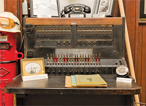
Figure 13-21 Ancient telephone switchboard, just because
EXAM TIP A company that provides local telephone service to individual customers is called a Local Exchange Carrier (LEC). A company that provides long-distance service is called an Interexchange Carrier (IXC). Classically, LECs owned the central offices and IXCs owned the lines and equipment that interconnected them. Over time, the line between LECs and IXCs has become very blurred.
Because the PSTN was designed long before computers were common, it was designed to work with only one type of data: sound. Here’s how it works. The telephone’s microphone takes the sound of your voice and translates it into an electrical analog waveform. The telephone then sends that signal through the PSTN line to the phone on the other end of the connection. That phone translates the signal into sound on the other end using its speaker. Note the word analog. The telephone microphone converts the sounds into electrical waveforms that cycle 2400 times a second. An individual cycle is known as a baud. The number of bauds per second is called the baud rate. Pretty much all phone companies’ PSTN lines have a baud rate of 2400. PSTN connections use a connector called RJ-11. It’s the classic connector you see on all telephones (Figure 13-22).

Figure 13-22 RJ-11 connectors (top and side views)
When you connect your modem to a phone jack, the line then runs to either your network interface unit (NIU) or the demarc. The term “network interface unit” usually describes the small box on the side of a home that accepts the incoming lines from the telephone company and then splits them to the different wall outlets. “Demarc” more commonly describes large connections used in businesses. The terms always describe the interface between the lines the telephone company is responsible for and the lines for which you are responsible (Figure 13-23).

Figure 13-23 Typical home demarc
Computers, as you know, don’t speak analog—only digital/binary (0 or 1) will do. In addition, the people who invented the way PCs communicate decided to divide any digital signal going in and out of your computer into 8 bits at a time. To connect over phone lines, PCs need two devices: one that converts this 8-bit-wide (parallel) digital signal from the computer into serial (1-bit-wide) digital data and then another device to convert (modulate) the data into analog waveforms that can travel across PSTN lines.
You already know that the device that converts the digital data to analog and back is called a modem. A modem also contains a device called a Universal Asynchronous Receiver/Transmitter (UART). The UART takes the 8-bit-wide digital data and converts it into 1-bit-wide digital data and hands it to the modem for conversion to analog. The process is reversed for incoming data. Even though internal modems are actually both a UART and a modem, we just say the word “modem” (Figure 13-24).
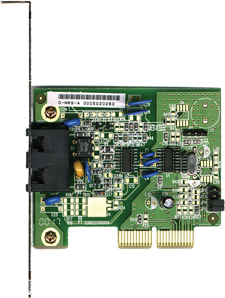
Figure 13-24 Internal modem
NOTE Modems and dial-up might seem 20th century to a lot of folks, but as of this writing, some 10 million Americans still use dial-up.
Bit Rates vs. Baud Rate
Modems use phone lines to transmit data at various speeds. These speeds cause a world of confusion and problems for computer people. This is where a little bit of knowledge becomes dangerous. Standard modems you can buy for your home computer normally transmit data at speeds up to 56 Kbps. That’s 56 kilobits per second, not 56 kilobaud! Many people confuse the terms baud and bits per second. This confusion arises because the baud rate and the bit rate are the same for modems until the data transfer rate surpasses 2400 bps.
A PSTN phone line takes analog samples of sound 2400 times a second. This standard sampling size was determined a long time ago as an acceptable rate for sending voice traffic over phone lines. Although 2400-baud analog signals are fine for voice communication, they are a big problem for computers trying to send data because computers only work with digital signals. The job of the modem is to take the digital signals it receives from the computer and send them out over the phone line in an analog form, using the baud cycles from the phone system. A 2400-bps modem—often erroneously called a 2400-baud modem—uses 1 analog baud to send 1 bit of data.
As technology progressed, modems became faster and faster. To get past the 2400-baud limit, modems modulated the 2400-baud signal multiple times in each cycle. A 4800-bps modem modulated 2 bits per baud, thereby transmitting 4800 bps. All PSTN modem speeds are a multiple of 2400, with the latest (and last) generation of modems achieving 2400 × 24 = 57,600 bps (56 Kbps).
V Standards
For two modems to communicate with each other at their fastest rate, they must modulate signals in the same fashion. The two modems must also negotiate with, or query, each other to determine the fastest speed they share. The modem manufacturers themselves originally standardized these processes as a set of proprietary protocols. The downside to these protocols was that unless you had two modems from the same manufacturer, modems often would not work together. In response, the International Telegraph and Telephone Consultative Committee (CCITT), a European standards body, established standards for modems. These standards, known generically as the V standards, define the speeds at which modems can modulate. The most common of these speed standards are as follows:
• V.22 1200 bps
• V.22bis 2400 bps
• V.32 9600 bps
• V.32bis 14,400 bps
• V.34 28,000 bps
• V.90 57,600 bps
• V.92 57,600 bps
The current modem standard now on the market is the V.92 standard. V.92 has the same download speed as the V.90, but upstream rates increase to as much as 48 Kbps. If your modem is having trouble getting 56-Kbps rates with V.90 in your area, you will not notice an improvement. V.92 also offers a Quick Connect feature that implements faster handshaking to cut connection delays. Finally, the V.92 standard offers a Modem On Hold feature that enables the modem to stay connected while you take an incoming call or even initiate an outgoing voice call. This feature only works if the V.92 server modem is configured to enable it.
In addition to speed standards, the CCITT, now known simply as the International Telecommunication Union (ITU), has established standards controlling how modems compress data and perform error checking when they communicate. These standards are as follows:
• V.42 Error checking
• V.42bis Data compression
• V.44 Data compression
• MNP5 Both error checking and data compression
EXAM TIP Do not memorize these V standards—just know what they do.
The beauty of these standards is that you don’t need to do anything special to enjoy their benefits. If you want the theoretical 56-Kbps data transfers, for example, you simply need to ensure that the modems in the local system and the remote system both support the V.90 standard.
ISDN
PSTN lines traditionally just aren’t that good. While the digital equipment that connects to a PSTN supports a full 64-Kbps DS0 channel, the combination of the lines themselves and the conversion from analog to digital means that most PSTN lines rarely go faster than 33 Kbps—and, yes, that includes the 56-Kbps connections.
A PSTN telephone connection has many pieces. First, there’s the modem in your computer that converts the digital information to analog. Then there’s the phone line that runs from your phone out to your NIU and into the central office. The central office stores the modems that convert the analog signal back to digital and the telephone switches that interconnect multiple individual local connections into the larger telephone network. A central office switch connects to long-distance carriers via high-capacity trunk lines (at least a T1) and also connects to other nearby central offices. The analog last mile was an awful way to send data, but it had one huge advantage: most everyone owned a telephone line.
During this upgrade period, customers continued to demand higher throughput from their phone lines. The phone companies were motivated to come up with a way to generate higher capacities. Their answer was fairly straightforward: make the last mile digital. Since everything but the last mile was already digital, by adding special equipment at the central office and the user’s location, phone companies felt they could achieve a true, steady, dependable throughput of 64 Kbps per line over the same copper wires already used by PSTN lines. This process of sending telephone transmission across fully digital lines end-to-end is called Integrated Services Digital Network (ISDN) service.
NOTE ISDN also supports voice but requires special ISDN telephones.
ISDN service consists of two types of channels: Bearer channels (B channels) carry data and voice information using standard DS0 channels (64 Kbps), whereas Delta channels (D channels) carry setup and configuration information at 16 Kbps. Most ISDN providers let the user choose either one or two B channels. The more common setup is two B/one D, called a Basic Rate Interface (BRI) setup. A BRI setup uses only one physical line, but each B channel sends 64 Kbps, doubling the throughput total to 128 Kbps.
Another type of ISDN is called Primary Rate Interface (PRI). ISDN PRI is actually just a full T1 line, carrying 23 B channels.
The physical connections for ISDN bear some similarity to PSTN modems. An ISDN wall socket is usually something that looks like a standard RJ-45 network jack. This line runs to your demarc. In home installations, many telephone companies install a second demarc separate from your PSTN demarc. The most common interface for your computer is a device called a terminal adapter (TA). TAs look like regular modems and, like modems, come in external and internal variants. You can even get TAs that also function as hubs, enabling your system to support a direct LAN connection (Figure 13-25).

Figure 13-25 A TeleWell ISDN terminal adapter
EXAM TIP Remember, a B channel is a DS0 channel.
You generally need to be within approximately 18,000 feet of a central office to use ISDN. When you install an ISDN TA, you must configure the other ISDN telephone number you want to call, as well as a special number called the Service Profile ID (SPID). Your ISP provides the telephone number, and the telephone company gives you the SPID. (In many cases, the telephone company is also the ISP.) Figure 13-26 shows a typical installation screen for an internal ISDN TA in an old version of Windows. Note that each channel has a phone number in this case.

Figure 13-26 ISDN settings in an old version of Windows
DSL
Many telephone companies offer a digital subscriber line (DSL) connection, a fully digital, dedicated (no phone number) connection. DSL represented the next great leap forward past ISDN for telephone lines. A physical DSL connection manifests as just another PSTN connection, using the same telephone lines and RJ-11 jacks as any regular phone line. DSL comes in a number of versions, but the two most important to know for the CompTIA Network+ exam are symmetric DSL (SDSL) and asymmetric DSL (ADSL).
SDSL
SDSL provides equal upload and download speeds and, in theory, provides speeds up to 15 Mbps, although the vast majority of ISPs provide packages ranging from 192 Kbps to 9 Mbps.
ADSL
ADSL uses different upload and download speeds. ADSL download speeds are much faster than the upload speeds. Most small office and home office (SOHO) users are primarily concerned with fast downloads for things like Web pages and can tolerate slower upload speeds. ADSL provides theoretical maximum download speeds up to 15 Mbps and upload speeds up to 1 Mbps. Real-world ADSL download speeds vary from 384 Kbps to 15 Mbps, and upload speeds go from as low as 128 Kbps to around 768 Kbps. ADSL is less expensive than SDSL.
NOTE AT&T (along with other telecoms) uses a very fast DSL version in some of its Internet offerings called very-high-bit-rate DSL (VDSL). The current version, VDSL2, can provide simultaneous upload and download speeds in excess of 100 Mbps, though only at short distances (~300 meters). Typical speeds using this technology are a lot slower, in the range of 8 to 16 Mbps down and 1 to 2 Mbps up.
DSL Features
One nice aspect of DSL is that you don’t have to run new phone lines. The same DSL lines you use for data can simultaneously transmit your voice calls.
All versions of DSL have the same central office–to–end user distance restrictions as ISDN—around 18,000 feet from your demarc to the central office. At the central office, your DSL provider has a device called a DSL Access Multiplexer (DSLAM) that connects multiple customers to the Internet.
As you’ll recall from Chapter 5, the DSL modem in your house is considered a termination point, a demarc. Any DSL modem today is a smart jack, a NIU that enables loopback testing so the ISP can remotely check your line and box.
Installing DSL
DSL operates using your preexisting telephone lines (assuming they are up to specification). This is wonderful but also presents a technical challenge. For DSL and your run-of-the-mill POTS line to coexist, you need to filter out the DSL signal on the POTS line. A DSL line has three information channels: a high-speed downstream channel, a medium-speed duplex channel, and a POTS channel.
Segregating the two DSL channels from the POTS channel guarantees that your POTS line will continue to operate even if the DSL fails. You accomplish this by inserting a filter on each POTS line, or a splitter mechanism that allows all three channels to flow to the DSL modem but sends only the POTS channel down the POTS line. The DSL company should provide you with a few POTS filters for your telephones. If you need more, most computer/electronics stores stock DSL POTS filters.
NOTE If you install a telephone onto a line in your home with DSL and you forget to add a filter, don’t panic. You won’t destroy anything, although you won’t get a dial tone either! Just insert a DSL POTS filter and the telephone will work.
A common early DSL installation consisted of a DSL modem connected to a telephone wall jack and to a standard network interface card (NIC) in your computer (Figure 13-27). The DSL line ran into a DSL modem via a standard phone line with RJ-11 connectors. Today you’d add a router in between the DSL modem and the wall jack.
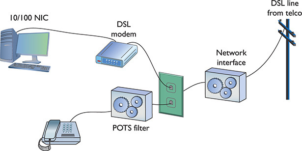
Figure 13-27 A DSL modem connection between a PC and telco
The DSL modem connects to the gateway router with a Cat 5/6 patch cable, which, in turn, connects to the company’s switch. Figure 13-28 shows an ADSL modem and a router.
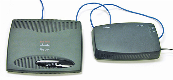
Figure 13-28 DSL connection
The first generation of DSL providers used a bridged connection; once the DSL line was running, it was as if you had snapped an Ethernet cable into your NIC. You were on the network. Those were good days for DSL. You just plugged your DSL modem into your NIC and, assuming your IP settings were whatever the DSL folks told you to use, you were running.
The DSL providers didn’t like that too much. There was no control—no way to monitor who was using the DSL modem. As a result, the DSL folks started to use Point-to-Point Protocol over Ethernet (PPPoE), a protocol that was originally designed to encapsulate PPP frames into Ethernet frames. The DSL people adopted it to make stronger controls over your DSL connection. In particular, you could no longer simply connect; you now had to log on with an account and a password to make the DSL connection. PPPoE is now predominant on DSL. If you get a DSL line, your operating system has software to enable you to log onto your DSL network. Most SOHO routers come with built-in PPPoE support, enabling you to enter your user name and password into the router itself (Figure 13-29).

Figure 13-29 PPPoE settings in SOHO router
Broadband Cable
The first big competition for ADSL came from the cable companies. A majority of houses in America have a coax cable for cable TV. In a moment of genius, the cable industry realized that if it could put the Home Shopping Network and the History Channel into every home, why not provide Internet access? The entire infrastructure of the cabling industry had to undergo some major changes to deal with issues like bidirectional communication, but cable modem service quickly became common in the United States. Cable modems are now as common as cable TV boxes.
Cable modems have the impressive benefit of phenomenal top speeds. These speeds vary from cable company to cable company, but most advertise speeds in the 5 to 200 Mbps range. Many cable modems provide a throughput speed of 30 to 200 Mbps for downloading and 5 Mbps to 10 Mbps for uploading—there is tremendous variance among different providers.
In a cable modem installation, the cable modem connects to an outlet via a coaxial cable. It’s separate from the one that goes to the television. It’s the same cable line, just split from the main line as if you were adding a second cable outlet for another television. A cable modem connects to a router, which in turn connects to a PC using a standard NIC and UTP cabling (Figure 13-30).

Figure 13-30 Cable modem
Cable modems connect using coax cable to a head end, similar to a telephone company’s central office. Head ends, in turn, connect to the cable company’s network. This network uses a unique protocol called Data Over Cable Service Interface Specification (DOCSIS). The current specification is DOCSIS 3.1.
You’ll have a hard time telling a cable modem from a DSL modem. The only difference, other than the fact that one will have “cable modem” printed on it whereas the other will say “DSL modem,” is that the cable modem has a coax F-connector and an RJ-45 connector; the DSL modem has an RJ-11 connector and an RJ-45 connector.
Cable companies aggressively market high-speed packages to business customers, making cable a viable option for businesses.
Satellite
Living in the countryside may have its charms, but you’ll have a hard time getting high-speed Internet out on the farm. For those too far away to get anything else, satellite may be your only option. Satellite access comes in two types: one-way and two-way. One-way means that you download via satellite, but you must use a PSTN/dial-up modem connection for uploads. Two-way means the satellite service handles both the uploading and downloading.
NOTE Companies that design satellite communications equipment haven’t given up on their technology. At the time of this writing, at least one company, HughesNet, offered download speeds up to 25 Mbps. You can surf with that kind of speed!
Satellite requires a small satellite antenna, identical to the ones used for satellite television. This antenna connects to a satellite modem, which, in turn, connects to your PC or your network (Figure 13-31).

Figure 13-31 Satellite connection
EXAM TIP Neither cable modems nor satellites use PPP, PPPoE, or anything else that begins with three Ps.
Fiber
DSL was the first popular last-mile WAN option, but over the years cable modems have taken the lead. In an attempt to regain market share, telephone providers rolled out fiber-to-the-home/fiber-to-the-premises options that are giving the cable companies a scare. In the United States, two companies, AT&T and Verizon (Fios), offer Internet connectivity, television, and phone services at super speeds. Some markets also have Internet-only fiber offerings, such as Google Fiber, where users connect at 1 Gbps.
To make rollouts affordable, most fiber-to-the-home technologies employ a version of passive optical network (PON) architecture that uses a single fiber to the neighborhood switch and then individual fiber runs to each final destination. PON uses WDM to enable multiple signals to travel on the same fiber and then passively splits the signal at the switch to send traffic to its proper recipient.
NOTE Most municipalities in the United States have very tight deals in place with telephone and cable companies, allowing little room for any other high-speed Internet service. A few cities have bucked the regional monopolies and done pretty well, such as Chattanooga, Tennessee. Their publicly owned electric utility—EPB—rolled out fiber to every home and business by 2011 and currently offers Internet speeds up to 10 Gbps.
Which Connection?
With so many connection options for homes and small offices, making a decision is often a challenge. Your first question is availability: Which services are available in your area? The second question is, how much bandwidth do you need? The latter is a question of great debate. Most services are more than happy to increase service levels if you find that a certain level is too slow. I usually advise clients to start with a relatively slow level and then increase if necessary. After all, once you’ve tasted the higher speeds, going slower is hard, but the transition to faster is relatively painless!
Using Remote Access
Because most businesses are no longer limited to a simple little shop like you would find in a Dickens novel, many people need to be able to access files and resources over a great distance. Enter remote access. Remote access uses WAN and LAN connections to enable a computer user to log onto a network from the other side of a city, a state, or even the globe. As people travel, information has to remain accessible. Remote access enables users to connect a server at the business location and log into the network as if they were in the same building as the company. The only problem with remote access is that there are so many ways to do it! I’ve listed the six most common forms of remote access here:
• Dial-up to the Internet Using a dial-up connection to connect to your ISP
• Private dial-up Using a dial-up connection to connect to your private network
• Virtual private network (VPN) Using an Internet connection to connect to a private network
• Dedicated connection Using a non-dial-up connection to another private network or the Internet
• Remote terminal Using a terminal emulation program to connect to another computer
• VoIP Voice over IP
In this section, I discuss the issues related to configuring these six types of connections. After seeing how to configure these types of remote connections, I move into observing some security issues common to every type of remote connection.
NOTE You’ll see the term extranet more in books than in the day-to-day workings of networks and network techs. So what is an extranet? Whenever you allow authorized remote users to access some part of your private network, you have created an extranet.
Dial-Up to the Internet
Dialing up to the Internet is the oldest and least expensive method to connect to the Internet, but it is rare today. Even with broadband and wireless so prevalent, every self-respecting network tech (or maybe just old network techs like me) keeps a dial-up account as a backup. You buy a dial-up account from an ISP (many wireless and broadband ISPs give free dial-up—just ask). All operating systems come with dial-up support programs, but you’ll need to provide:
• A modem (most operating systems check for a modem before setting up a dial-up connection)
• The telephone number to dial (provided to you by the ISP)
• User name and password (provided to you by the ISP)
• Type of connection (dial-up always uses PPP)
• IP information (provided to you by the ISP—usually just DHCP)
Every operating system comes with the software to help you set up a dial-up connection. In Windows, you go to the Set up a dial-up connection option in the Network and Sharing Center (Figure 13-32). Whatever the name, this tool is what you use to create dial-up connections.

Figure 13-32 Dial-up in Windows
Private Dial-Up
A private dial-up connection connects a remote system to a private network via a dial-up connection. Private dial-up does not use the Internet! Private dial-up requires two systems. One system acts as a remote access server (RAS). The other system, the client, runs a connection tool (usually the same tool you just read about in the previous section).
In Windows, a RAS is a server running the Routing and Remote Access Service (RRAS), dedicated to handling users who are not directly connected to a LAN but who need to access file and print services on the LAN from a remote location. For example, when a user dials into a network from home using an analog modem connection, she is dialing into a RAS. See Figure 13-33. Once the user authenticates, she can access shared drives and printers as if her computer were physically connected to the office LAN.

Figure 13-33 Windows RRAS in action
NOTE When you run Microsoft’s Routing and Remote Access Service on a server, you turn that server into a remote access server.
You must set up a server in your LAN as a RAS server. That RAS server, which must have at least one modem, accepts incoming calls and handles password authentication. RAS servers use all the standard authentication methods (PAP, CHAP, EAP, 802.1X, and so on) and have separate sets of permissions for dial-in users and local users. You must also configure the RAS server to set the rights and permissions for all of the dial-in users. Configuring a RAS server is outside the scope of this book, however, because each one is different.
NOTE Remote access server refers to the hardware component (servers built to handle the unique stresses of a large number of clients calling in), but it can also refer to the software service component of a remote access solution. You might call it a catchall phrase. Most techs call RAS “razz,” rather than using the initials, “R-A-S.” This creates a seemingly redundant phrase used to describe a system running RAS: “RAS server.” This helps distinguish servers from clients and makes geeks happier.
Creating the client side of a private dial-up connection is identical to setting up a dial-up connection to the Internet. The only difference is that instead of having an ISP tell you what IP settings, account name, and password to use, the person who sets up the RAS server tells you this information (Figure 13-34).

Figure 13-34 Dial-up on macOS
VPNs
A VPN enables you to connect through a tunnel from a local computer to a remote network securely, as you’ll recall from the in-depth discussion in Chapter 11. Refer to that chapter for the details.
Dedicated Connection
Dedicated connections are remote connections that are never disconnected. Dedicated connections can be broken into two groups: dedicated private connections between two locations and dedicated connections to the Internet. Dedicated private connections manifest themselves as two locations interconnected by a connection such as a T1 line (Figure 13-35).

Figure 13-35 Dedicated private connection
Each end of the T1 line goes into a router (after going through a CSU/DSU, of course). Note that this connection does not use the Internet in any way—it is not a VPN connection. Private dedicated connections of this type are expensive and are only used by organizations that need the high bandwidth and high security these connections provide. These connections are invisible to the individual computers on each network. There is no special remote connection configuration of the individual systems, although you may have to configure DHCP and DNS servers to ensure that the network runs optimally.
DSL and Cable
Dedicated connections to the Internet are common today. Cable modems and DSL have made dedicated connections to the Internet inexpensive and very popular. In most cases, you don’t have to configure anything in these dedicated connections. Figure 13-36 shows the DSL wizard built into Windows 7. This program enables you to connect by entering your PPPoE information for your ADSL connection. Once started, these programs usually stay running in the system tray until your next reboot.

Figure 13-36 PPPoE connection
Cable Issues
Dedicated cable connections provide the only exception to the “plug them in and they work” rule because most cable networks bring television and often voice communication into the same line. This complicates things in one simple way: splitters.
If you have a cable connection coming to your house and you have a television set in two rooms, how do you get cable in both rooms? Easy, right? Just grab a two-way splitter from an electronics store and run an extra pair of cables, one to each room. The problem comes from the fact that every time you split a cable signal, the signal degrades by half. This is called, logically, a split cable problem.
The quality of a signal can be measured in decibels (dB), a unit that describes a ratio between an ideal point—a reference point—and the current state of the signal. When discussing signal strength, a solid signal is 0 dB. When that signal degrades, it’s described as a dB loss and a negative number. An increase in signal is gain and gets a positive number. Decibels are logarithmic units. This means the scale is in simple numbers, but each additional unit reflects a large percentage change. Adding 10 dB to a signal makes it 1000 percent stronger.
For example, when you split a cable signal into two, you get half the signal strength into each new cable. That’s described as a –3 dB signal. Split it again and you’ve got a –6 dB signal. Although 6 isn’t a big number in standard units, it’s horribly huge in networking. You might have a 20-Mbps cable connection into your house, but split it twice and you’re left with a 5-Mbps connection. Ouch!
The standard procedure with cable connections is to split them once: one cable goes to the cable modem and the other to the television. You can then split the television cable into as many connections as you need or can tolerate as far as reception quality.
Remote Terminal
You can use a terminal emulation program to create a remote terminal, a connection on a faraway computer that enables you to control that computer as if you were sitting in front of it, logged in. Terminal emulation has been a part of TCP/IP from its earliest days, in the form of good-old Telnet. Because it dates from pre-GUI days, Telnet is a text-based utility; most modern operating systems are graphical, so there was a strong desire to come up with graphical remote terminal tools. Citrix Corporation made the first popular terminal emulation products—the WinFrame/MetaFrame products (Figure 13-37). (Their current product is called XenApp.)

Figure 13-37 Citrix MetaFrame
Remote terminal programs all require a server and a client. The server is the computer to be controlled. The client is the computer from which you do the controlling. Citrix created a standard called Independent Computing Architecture (ICA) that defined how terminal information was passed between the server and the client. Citrix made a breakthrough product—so powerful that Microsoft licensed the Citrix code and created its own product called Windows Terminal Services. Not wanting to pay Citrix any more money, Microsoft then created its own standard called Remote Desktop Protocol (RDP) and unveiled a new remote terminal called Remote Desktop Connection (RDC) starting with Windows XP (so it’s been around a long time). Figure 13-38 shows Windows Remote Desktop Connection running on a Windows 10 system, connecting to a Windows Server.

Figure 13-38 RDC in action
NOTE All RDP applications run on port 3389 by default.
A number of third parties make absolutely amazing terminal emulation programs that run on any operating system. The best of these, VNC (VNC stands for Virtual Network Computing), doesn’t let you share folders or printers because it is only a terminal emulator (Figure 13-39), but it runs on every operating system, is solid as a rock, and even runs from a Web browser. It works nicely in Secure Shell (SSH) tunnels for great security, plus it comes, by default, with every copy of macOS and almost every Linux distro. Why bother sharing if you can literally be at the screen? Oh, and did I mention that VNC is completely free?

Figure 13-39 VNC in action
VoIP
Voice over IP (VoIP) uses an IP network to transfer voice calls. VoIP works so well because it uses an existing network you’re already paying for (your Internet connection) to replace another network you’re also paying for (PSTN lines). The technology needed for VoIP isn’t very challenging, but making a VoIP system that’s standardized so everyone can use it (and still contact those who choose to use PSTN) requires international standards, making it quite a bit harder. VoIP is still a very fractured world, but it’s getting closer to universally adopted standards—one day everyone will be able to contact everyone else, no matter what brand of VoIP they use. To do this, you need to know three important standards: RTP, SIP, and H.323.
RTP
The Real-time Transport Protocol (RTP), the heavily adopted bedrock of VoIP standards, defines the type of packets used on the Internet to move voice or data from a server to clients. The vast majority of VoIP solutions available today use RTP.
SIP and H.323
Session Initiation Protocol (SIP) and H.323 handle the initiation, setup, and delivery of VoIP sessions. SIP and H.323 both run on top of RTP. Most VoIP solutions are either SIP/RTP or H.323/RTP. SIP uses TCP ports 5060 and 5061. H.323 uses port 1720. SIP and H.323 both have methods for handling multicasting.
Skype
Almost every VoIP solution available today uses SIP or H.323 running on top of RTP, with one huge exception: the very famous and incredibly popular Skype. Skype was unveiled in 2003 by Niklas Zennström, a Swedish computer guy famous for inventing the Kazaa peer-to-peer file-sharing system. Skype is completely different from and completely incompatible with any other type of VoIP solution: Skype doesn’t use servers, but instead uses a peer-to-peer topology that is identical to the old Kazaa network. Skype calls are also encrypted using a proprietary encryption method. No one has a standard method for VoIP encryption at this time, although many smart people are working hard on the issue.
Streaming Media with RTSP
VoIP isn’t the only thing that takes advantage of protocols such as RTP. Streaming video is now mainstream and many streaming video severs (Windows Media Player, QuickTime, and many others) use a popular protocol called Real-Time Streaming Protocol (RTSP). Like SIP and H.323, RTSP runs on top of RTP. RTSP has a number of features that are perfect for video streaming such as the ability to run, pause, and stop videos. RTSP runs on TCP port 554.
In-Band Management
VNC and SSH enable in-band management of resources, meaning software installed on both the client and the remote system enables direct control over resources. The interaction uses the primary network connection for both devices, thus it’s in-band and sharing resources (and traffic) with the regular network.
This is fast and inexpensive, but has a couple of drawbacks in a busy network. First, the remote system must be booted up with its operating system fully loaded for this to work. Second, putting management of a remote system on the main network doesn’t provide as much security or control as a dedicated, alternative connection would provide.
Many servers employ lights-out-management (LOM) capabilities that enable out-of-band management to address these issues. We’ll see a lot more of these technologies when we discuss network monitoring and management in Chapter 20.
WAN Troubleshooting Scenarios
Competent network techs can recognize and deal with typical remote connectivity issues in a WAN setting. Sometimes the problem lies well beyond the job description, but that’s when the tech knows to escalate the problem. This section looks at four very important CompTIA Network+ problem areas: loss of Internet connectivity, interface errors, DNS issues, and interference.
Loss of Internet Connectivity
Given that the core reason to use all these forms of remote connectivity is to get to the Internet in the first place, I don’t look at loss of Internet connectivity as a problem. It’s more a symptom. Be sure to watch for WAN scenarios on the CompTIA Network+ exam that really aren’t always WAN scenarios.
If you want to connect a computer to the Internet, that computer needs a legitimate IP address, subnet mask, default gateway, and DNS address. These needs don’t change whether you connect through a Gigabit Ethernet wired network or through a cable modem. Use the utilities already covered in the book in such a scenario, such as ping, ipconfig, netstat, nslookup, and so forth, to verify that the device has a solid IP connection.
Interface Errors
CompTIA loves to use the term interface errors as a catchall term to describe the many connections between your computer and the remote connection that enables you to get to the Internet. In a WAN scenario you’ll have at least one more interface than in a native Ethernet world. Think about a typical office environment.
Local Ethernet Interface/LAN Interfaces
When you use DSL or cable or any other form of remote connection, it’s very easy to forget all of the LAN connections that make connectivity possible. It’s plausible, if you’re anything like me, that you’ll call an ISP like Comcast or AT&T and complain, only to find that you don’t have a patch cable plugged into the right connection on the back of the computer. (Not that I’ve ever done this. Twice.)
Before you blame Comcast or AT&T for losing your connection, make sure to verify that everything on your end is in order. Is the computer properly connected to the LAN? If you are using a router, is it providing good IP information? Can you access the router and see if it is reporting that it has a proper upstream connection? Before you blame the WAN interface, always first confirm everything on the LAN.
Modem Interface
It doesn’t really matter what type of remote connection you use. There’s always a modem. Be careful here: “modem” is the term I use for any box that sits in your location and connects your LAN to the WAN, even if your ISP calls it something loftier like: cable modem, router, or customer premises equipment (CPE). Everything said here that references “modem” works for whatever CPE device your ISP provides.
The modem’s job is to connect your LAN to the WAN, so by definition it’s going to have at least two interfaces: one to the LAN and one to the WAN. First of all, familiarize yourself with the lights on your modem, preferably before you have problems. Any modem is going to have a power LED, link LEDs to both the LAN and the WAN, and some form of activity LED. Study them first when you’re looking for interface issues. In almost every case of a bad interface, you’ll verify connections and reset the modem.
DNS Issues
There is one specific DNS issue that comes up in WANs: choosing what DNS server to use. Every ISP has their own DNS server(s) and, in almost every case, your modem is going to propagate those DNS settings down to every device in your LAN. In most cases there isn’t any problem with this, but there are two cases where you might want to consider manually adding DNS to your local devices or your local router. First, an ISP’s DNS servers can fail.
Second, some ISPs notoriously use DNS helpers, DNS servers that redirect your browser to advertising when you type in an incorrect URL.
In either of these cases, the rules you learned back in Chapter 6, “TCP/IP Basics,” still apply. Get yourself a fast public DNS IP address—I love the Google 8.8.8.8 and 8.8.4.4 addresses—and at the very least load one of those as a secondary DNS server.
NOTE In 2017, the Global Cyber Alliance (a group dedicated to reducing cyber crime) and IBM and other players launched Quad9, a free public DNS server that blocks the bad domains and whitelists the good domains. Phishing and scammer domains are blocked; Google and Amazon, for example, are not. Check it out by changing your DNS server to 9.9.9.9. The computer you save might be your own!
Interference
Interference at the WAN level—that CompTIA Network+ techs can fix—generally implies the connection between the LAN and the WAN. The point at which the ISP’s responsibility ends and the customer’s begins is the demarc. Let’s look at both sides of the demarc for interference.
On the customer side, the CPE can create problems. In a busy office building, for example, new installations or connections can add electromagnetic interference (EMI) and create disturbances. New things added to old environments, in other words, can create interference in existing networks.
When my company changed locations, for example, the building we moved into had several offices, connected to Internet and corporate WANs with several dedicated T1 lines (Figure 13-40). With the local cable company offering 100-Mbps connections, we opted to have cable installed in the building for us (T1 at 1.5 Mbps, not so much).

Figure 13-40 Demarc at my office building
If the cable company had not been careful or used properly shielded boxes and cables, this could have wreaked havoc on the other folks in the building.
In a consumer space, the CPE doesn’t run into interference that would block connectivity at the demarc, unless you overly broaden the term “interference” to include “failure.” Then you can point to the “modem” as the only major failure culprit.
Once you go to the ISP side of the demarc, there’s not much interference involved, especially with existing, previously well-functioning networks. Again, WAN interference only happens if you extend the definition to include failure. Then storms, downed power lines, extraterrestrial activity, and so on can cause problems.
In a home network, there are only two times you should worry about interference in a WAN outside the demarc: during installation and when changing the connection in any way. Every form of remote connection has very clear interference tolerances, and you should have the installation tech verify this. Cable and DSL self-installations are a big issue here as most people don’t have access to the tools necessary to confirm their PSTN or coax cabling. If I’m installing a new DSL or cable modem, I refuse the self-install option and gladly pay the extra money to verify my cabling can handle the connection.
It’s incredibly easy to introduce interference into an otherwise perfectly functioning wired WAN connection by adding splitters, noisy devices, splices, and so on. This is especially true for tech folks (like your humble author) who have learned this the hard way. In general, be conservative when disturbing your WAN connection and be ready to call support if needed.
Chapter Review
Questions
1. What is the signal rate for DS0?
A. 1.544 Mbps
B. 64 Kbps
C. 2.048 Mbps
D. 128 Kbps
2. Which of the following provides the fastest throughput?
A. PSTN
B. ISDN BRI
C. ADSL
D. POTS
3. What is the popular Microsoft remote access server program called?
A. RRAS
B. Dial-Up Networking
C. Dial-Up Server
D. Microsoft Client for Networks
4. What device do you use to connect to a T1 line?
A. Router
B. CSU/DSU
C. Modem
D. WIC-2T
5. BRI ISDN uses _______________.
A. 1 B channel and 24 D channels
B. 24 B channels and 1 D channel
C. 1 B channel and 2 D channels
D. 2 B channels and 1 D channel
6. The V.90 standard defines a modem speed of _______________.
A. 56 Kbps
B. 33.6 K baud
C. 28.8 Kbps
D. 2400 baud
7. You have just had DSL installed at your house. Although the Internet connection is fast, your phones no longer work. What is the problem?
A. The installer failed to install the POTS filters on the phones.
B. Nothing; the phones can’t function at the same time as the Internet.
C. The house phone lines can’t handle the bandwidth of both the phone and DSL.
D. The DSL modem is missing the filter and is causing line interference.
8. What protocol do cable modems use?
A. ACMSIS
B. CMAS
C. DOCSIS
D. CCSIP
9. What is SONET used for?
A. Short-distance, high-speed, fiber-optic transmission
B. Long-distance, high-speed, fiber-optic transmission
C. Long-distance, low-speed, copper cable transmission
D. Short-distance, low-speed, copper cable transmission
10. What does SIP stand for?
A. Standard Initiation Protocol
B. System Internetworking Protocol
C. Session Initiation Protocol
D. Sector Information Protocol
Answers
1. B. DS0 operates at a constant rate of 64 Kbps.
2. C. ADSL can run up to 15 Mbps.
3. A. The popular Microsoft remote access server is called Routing and Remote Access Service, or RRAS.
4. B. A CSU/DSU is required to connect to a T1 line.
5. D. BRI ISDN uses two B channels and one D channel.
6. A. The V.90 standard defines a 56-Kbps modem speed.
7. A. The problem is that the installer did not install POTS filters on the jacks with phones attached.
8. C. Cable modems use DOCSIS (Data Over Cable Service Interface Specification).
9. B. SONET is used for long-distance, high-speed, fiber-optic transmission.
10. C. Session Initiation Protocol; SIP is one of the main protocols for VoIP.