
3D robot sander for artistically designed furniture
Abstract:
This chapter introduces a robotic sanding system for attractively designed furniture with free-formed surfaces. The system is developed using an industrial robot with an open-architecture controller. The system has two novel features. One is that the surface-following controller developed for robotic sanding allows the robot to simultaneously realize a delicate polishing force control and smooth position/orientation control. The other is that a conventional and complicated teaching task is not required at all. The proposed robot sander directly handles CL data generated from 3D CAD/CAM, so that such a teaching process can be omitted. It is demonstrated that the proposed system can successfully sand the curved surface of attractive furniture with an extremely good quality.
4.1 Background
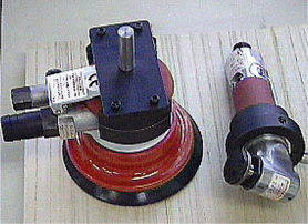
In the wooden furniture manufacturing industry, CAD/CAM systems and NC machine tools have been introduced widely and generally, so that the design and machining processes are rationalized. However, the sanding process after machining process is hardly automated yet, because it requires delicate and dexterous skills so as not to spoil the beauty and quality of the wooden surface. Up to now, several sanding machines have been developed for wooden materials. For example, the wide belt sander is used for flat workpieces constructing furniture. Also, the profile sander is suitable for sanding around edges. However, these conventional machines cannot be applied to the sanding task of the workpiece with a free-formed surface. Accordingly, we must depend on skilled workers who can not only perform appropriate force control of sanding tools but also deal with complex curved surface. Skilled workers usually use smaller, air-driven tools such as a double-action sanding tool and an orbital sanding tool as shown in Fig. 4.1.
Industrial robots have progressed remarkably and been applied to several tasks such as painting, welding, handling and so on. In these cases, it is important to precisely control the position of the end-effector attached to the tip of the robot arm. When robots are applied to polishing, deburring or grinding tasks, it is important to use some force control strategy so as not to damage the object. For example, polishing robots and finishing robots were presented in [34–38] Automated robotic deburring systems and grinding systems were also introduced in[39–43].
Surface-following control is a basic sanding strategy for industrial robots. It is known that two control schemes are needed to realize the surface-following control system. One is the position/orientation control of the sanding tool attached to the tip of the robot arm. The other is the force control to stably keep in contact along the curved surface of the workpiece. It should be noted that if the geometric information on the workpiece is unknown, then it is so difficult to satisfactorily control the contact force moving with a high speed [44]. To suppress overshoots and oscillations, for example, the feed rate must be given a small value. Furthermore, it is also difficult to control the orientation of the sanding tool, keeping in contact with the workpiece from normal direction.
In this chapter, a robotic sanding system is integrated for new designed furniture with free-formed curved surface. The robotic sanding system provides a practical surface-following control that allows industrial robots not only to adjust the polishing force through a desired impedance model in Cartesian space but also to follow a curved surface keeping contact with from normal direction. The polishing force is assumed to be the resultant force of contact force and kinetic friction force. We also describe how to apply the robotic sanding system to the task of sanding a wooden workpiece without complicated teaching process. A few experiments involving the sanding of wooden parts are shown to demonstrate the effectiveness and promise of the proposed robotic sanding system.
4.2 Feedfoward position/orientation control based on post-process of CAM
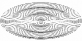
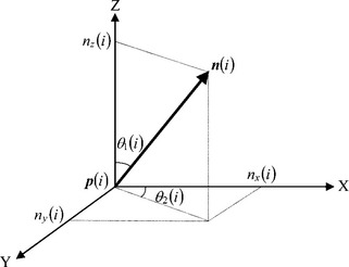
First of all, we discuss position/orientation control of an end-effector attached to the tip of a robot arm. A key point is that the position/orientation control system is designed feedforwardly so as not to disturb the force feedback control loop. In almost all cases, target workpieces are designed and machined by CAD/CAM systems and NC machine tools. Therefore, cutter location data can be referred to as the desired trajectory of position and orientation. The cutter location data are called CL data, and are generated from the main-processor of the CAM. The CL data have sequential points along the model surface given by a zigzag path, whirl path or spiral path. Fig. 4.2 shows an example of a whirl path based on contour lines, which are outputted by the main-processor of 3D CAD/CAM Unigraphics. In order to realize non-taught operation, we have already proposed a feedforward trajectory generator [22, 23] using the CL data, which yields the desired trajectory r(k) at the discrete time k given by Eq. (3.1). Here, the desired orientation vector Od(k) is considered from the viewpoint of the post-processor of CAM . We define two angles θ1(i),θ2(i) as shown in Fig. 4.3. θ1(i) and θ2(i) are the tool angles of inclination and rotation, respectively. Using θ1(i) and θ2(i), each component of n(i) is represented by
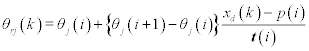
The desired tool angles θr1(k), θr2(k) of inclination and rotation at the discrete time k can be calculated as
where j = 1, 2. If Eq. (4.4) is substituted into Eqs. (4.1), (4.2), (4.3), we finally obtain
xd(k) and od(k) mentioned above are directly obtained from the CL data without any conventional complicated teaching, and used for the desired position and orientation of a sanding tool attached to a robot arm. Orientation velocity vector [υrx υry υrz]T according to the translational velocity vector given by Eqs. (3.6), (3.7) and (3.8) is obtained by
4.3 Hybrid position/force control with weak coupling
When an industrial robot conducts a task involving the maintaining of contact with a workpiece, the position and force must be controlled simultaneously and dexterously. The hybrid position/force control method was proposed to control compliant motions of a robot manipulator, by combining force and torque information with positional data to satisfy simultaneous position and force trajectory constraints specified in a convenient task related coordinate system [24].
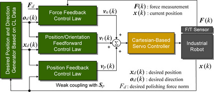
Here we consider a practical and applicable hybrid position/force control method which can easily be applied to open-architecture industrial robots. Basically, the proposed hybrid controller consists of force feedback loops and position feedforward loops in a Cartesian coordinate system. Hence, the position control system and force control system do not interfere with each other, so that the position will gradually deviate from the desired trajectory due to the manipulated variable of the force feedback loop. This phenomenon is a serious problem, for example, when developing an accurate mold polishing robot. The mold polishing robot is required to be able to exert stable force control and regular pick feed control. That means the compatibility between position control and force control should be realized. In order to cope with this problem, we have proposed a novel hybrid position/force control method with weak coupling between the position feedback loop and the force feedback loop. Fig. 4.4 shows the block diagram of the proposed controller, in which position feedback loops become active only in selected directions by using a switch matrix Sp = [Spx Spy Spz 0 0 0]T. Note that the force feedback control law generates the normal velocity υn = [υnx υny υnz 0 0 0]T given by Eq. (1.17), the position feedback law outputs the velocity υp = [υpx υpy υpz 0 0 0]T given by Eq. (4.15), and the position/orientation feedforward control law produces the velocity vector υt = [υtx υty υtz υrx υry υrz]T given by Eqs. (3.6), (3.7), (3.8) and (4.8). The summation of the vectors υn, υp and υt is output to the reference of the servo controller of the robot.
After this section, three applied examples of the proposed hybrid position/force control method are introduced. They are the 3D robot sander [11], the mold polishing robot [25]and the desktop-size orthogonal-type robot [76].
4.4 Robotic sanding system for wooden parts with curved surfaces
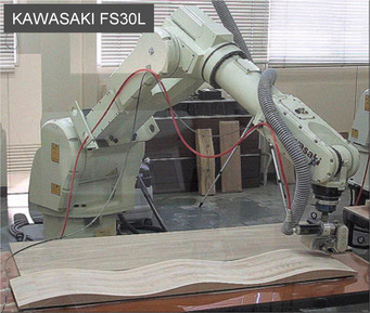
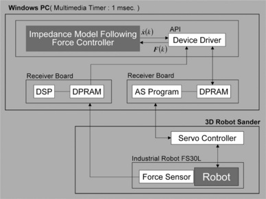
Recently, open-architecture industrial robots have been proposed to comply with various users’ requests with regard to application developments. The industrial robot has an open programming interface for Windows or Linux, so that we can try to program new functions such as force control, compliance control and so on. The six-DOFs (Degree of Freedoms) industrial robot shown in Fig. 4.5 is a model called FS30L with a PC-based controller provided by Kawasaki Heavy Industries. The proposed robotic sanding system is developed based on the industrial robot whose tip has a compact force sensor. A small sanding tool as shown in Fig. 4.1 can be easily attached to the tip of the robot arm via the force sensor. A PC is connected to the PC-based controller via an optical fiber cable. The PC-based controller provides several Windows Application Programming Interface (API) functions, such as servo control with joint angles, forward/inverse kinematics, coordinate transformation and so on. By using such API functions and a Windows timer, for instance, the position/orientation control at the tip of the robot arm can be realized easily and safely. In the following subsection, the surface-following controller is implemented for robotic sanding using the Windows API functions. Fig. 4.6 shows the hardware block diagram between the controller and Windows PC. Although the standard Windows timer was set to 10 msec, the actual rate measured by an oscilloscope was sometimes about 15 msec. To solve the problem, a stable and high sampling rate of 1 msec could be easily realized using the Windows multimedia timer. We confirmed the sampling rate of 1 msec by using a digital data logger.
4.5 Surface-following control for robotic sanding system
The robotic sanding system has two main features: one is that neither conventional complicated teaching tasks nor post-processor (CL data → NC data) is required; the other is that the polishing force acting on the sanding tool and the tool’s position/orientation are simultaneously controlled along free-formed curved surface. In this section, a surface-following control method, indispensable for realizing the features, is described in detail.
A robotic sanding task needs a desired trajectory so that the sanding tool attached to the tip of the robot arm can follow the object’s surface, keeping contact with the surface from the normal direction. In executing a motion using an industrial robot, the trajectory is generally obtained in advance, e.g., through conventional robotic teaching process. When the conventional teaching for an object with a complex curved surface is conducted, the operator has to input a large number of teaching points along the surface. Such a teaching task is complicated and time-consuming.
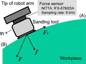
Next, a sanding strategy for dealing with the polishing force is described in detail [11, 83]. The polishing force vector F(k) = [Fx(k) Fy(k) Fz(k)]T is assumed to be the resultant force of contact force vector f (k) = [fx(k) fy(k) fz(k)]T and kinetic friction force vector − Fr(k) = −[Frx(k) Fry(k) Frz(k)]T that are given to the workpiece as shown in Fig 4.7, where the sanding tool is moving along on the surface from (A) to (B). Fr (k) is written by
where diag(μx,μy,μz)![]() f(k)
f(k)![]() (υt(k)/
(υt(k)/![]() υt(k)
υt(k)![]() ) is the Coulomb friction, and diag(ηx,ηy,ηz) υt(k) is the viscous friction. μi and ηi (i = x, y, z) are the i-directional coefficients of Coulomb friction per unit contact force and of viscous friction, respectively. Each friction force is generated by f(k) and υt(k), respectively. F(k) is represented by
) is the Coulomb friction, and diag(ηx,ηy,ηz) υt(k) is the viscous friction. μi and ηi (i = x, y, z) are the i-directional coefficients of Coulomb friction per unit contact force and of viscous friction, respectively. Each friction force is generated by f(k) and υt(k), respectively. F(k) is represented by
The polishing force magnitude can be easily measured using a three-DOFs force sensor attached between the tip of the arm and the sanding tool, which is given by
where SFx(k), SFy(k) and SFZ(k) are the each directional component of force sensor measurements in sensor coordinate system. The force sensor used is the NITTA IFS-67M25A with a sampling rate of 8 kHz. Although the IFS-67M25A is a six-DOFs force/moment sensor, the moment components were ignored because the moment data were not needed in force control system. In the following subsection, the error Ef(k) of polishing force magnitude is calculated by
4.6 Feedback control of polishing force
In the wooden furniture manufacturing industry, skilled workers usually use small, air-driven tools to finish the surface after machining or painting. These types of tools cause high frequency and large magnitude vibrations, so that it is difficult for the skilled workers to sand the workpiece keeping the polishing force a desired value. Consequently, undesirable unevenness tends to appear on the sanded surface.
In order to achieve a good surface finish, it is fundamental to stably control the polishing force. When the robotic sanding system runs, the polishing force is controlled by the impedance model following force control with integral action given by
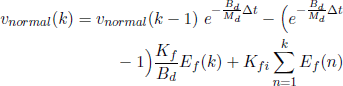
where υnormal (k) is the velocity scalar; Kf is the force feedback gain; Kfi is the integral control gain; Md and Bd are the desired mass and desired damping coefficients, respectively. ∆t is the sampling width. Using υnormal (k), the normal velocity vector υn(k) = [υnx(k) υny(k) υnz(k)] at the center of the contact point is represented by
where od(k) is the normal vector at the contact point, which are obtained from Eqs. (4.5), (4.6) and (4.7).
4.7 Feedforward and feedback control of position
Currently, wooden furniture is designed and machined with 3D CAD/CAM systems and NC machine tools, respectively. Accordingly, the CL data generated from the mainprocessor of the CAM (as shown in Fig. 4.8) can be used to obtain the desired trajectory of the sanding tool. The tool path (CL data) as shown in Fig 4.8, which is calculated in advance based on a zigzag path, is considered to be a desired trajectory of the sanding tool. The block diagram of the surface-following controller implemented in the robot sander is shown in Fig. 4.4. The position and orientation of the tool attached to the tip of the robot arm are feedforwardly controlled by the tangential velocity υt(k) and rotational velocity υr(k), respectively referring xd(k) and od(k). υt(k) is given through an open-loop action so as not to interfere with the force feedback loop. The polishing force is regulated by υn(k) which is perpendicular to υt(k). υn(k) is given to the normal direction referring the orientation vector od(k).
Figure 4.8 Zigzag path generated from the main-processor of a CAM system. Each through point has a position and an orientation components
It should be noted, however, that using only υt(k) is not enough to precisely carry out the desired trajectory control along the CL data: Actual trajectory tends to deviate from the desired one, so that the constant pick feed (e.g., 20 mm) cannot be performed. This undesirable phenomenon leads to a lack of uniformity on the surface. To overcome this problem, a simple position feedback loop with small gains is added as shown in Fig. 4.4, so that the tool does not seriously deviate from the desired pick feed. The position feedback control law generates another velocity υp(k) given by
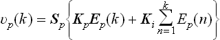
where Sp = diag(Spx, Spy, Spz) is a switch matrix to realize a weak coupling control in each direction. If Sp = diag(1,1,1), then the coupling control is active in all directions; whereas if Sp = diag(0,0,0), then the position feedback loop does not contribute to the force feedback loop in all directions. Ep(k) = xd(k) − x(k) is the position error vector. x(k) is the current position of the sanding tool attached to the tip of the arm and is obtained from the forward kinematics of the robot. Kp = diag(Kpx, Kpy, Kpz) and Ki = diag(Kix, Kiy, Kiz) are the position feedback gain and its integral gain matrices, respectively. Each component of Kp and Ki must be set to small values so as not to obviously disturb the force control loop.Finally recomposed velocities ![]() ,
, ![]() and
and ![]() are summed up to a velocity command υ(k), and the υ(k) is given to the reference of the Cartesian-based servo controller of the industrial robot.
are summed up to a velocity command υ(k), and the υ(k) is given to the reference of the Cartesian-based servo controller of the industrial robot.
It can be guessed that the complete six constraints, which consist of three-DOFs positions and three-DOFs forces in a constraint frame, cannot be simultaneously satisfied [10]. However, the delicate cooperation between the position feedback loop and force feedback loop is an important key point to achieve successful robotic sanding with a curved surface.
4.8 Hyper CL data
One of the features of the robot sander is that the CL data are referred to as the desired trajectory of the sanding tool attached to the tip of the arm. Therefore, the complicated teaching process can be completely omitted. It is also useful that no post-processor optionally included in CAM is required to transform the CL data into the NC data, i.e., the robot sander does not run based on the NC data but the CL data. The conventional CL data mainly deal with static positions and orientations along the curved surface of a model. In order to realize such a skillful sanding as skilled workers perform, we propose hyper CL data that can describe serviceable items as shown in Fig. 4.9. For example, the following conditions can be specified:
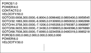
1. Desired polishing force acting between a sanding tool and a workpiece.
2. Sanding power such as motor torque or air pressure.
The desired polishing force Fd N is recognized by
The air pressure P Pa of an air-driven sanding tool is regulated by
The feed rate norm ||υt|| mm/s in contact state is set by
The task mode change from contact mode to noncontact mode is switched by
where the sanding tool takes off from the workpiece with υm mm/s to the normal direction; d mm is the distance to be moved. On the other hand, the task mode change from noncontact mode to contact mode is switched by
where υ mm/s is the approaching velocity from the normal direction .Due to the hyper CL data, it has become possible to record sanding ability in detail.
4.9 Experimental result
In this subsection, the result of an experiment involving surface sanding experiment using the proposed robot sander is given. The overview of the robot sander developed, based on the KAWASAKI FS20, is shown in Fig. 4.10. The orbital sanding tool is widely used by skilled workers to sand or finish a workpiece with curved surfaces. The base of the orbital sanding tool can perform eccentric motions. That is why the orbital sander is not only a powerful sanding tool but also gives good surface finishing with fewer scratches. In this experiment, an orbital sanding tool is selected and attached to the tip of the robot arm via a force sensor. The diameter of the circular base and the eccentricity are 90 mm and 4 mm, respectively. The weight of the sanding tool is about 1.5 kg. When a sanding task is conducted, a circular pad with sanding paper is attached to the base.
Fig. 4.11 shows the sanding scene using the robot sander based on a KAWASAKI FS30L. In this case, the polishing force was satisfactorily controlled to a suitable value. Smaller, air-driven tools are usually used by skilled workers to sand wooden material used in furniture. These types of tools cause large amounts of noise and vibration. Furthermore, the system of force control consists of an industrial robot, force sensor, attachment, small air-driven tool, jig and wooden material. Because each is quite stiff, it is not easy to keep the polishing force a constant value without overshoot and oscillation. That is why the measured value of the polishing force tends to have spikes and noise. However, the result would be much better than the one given by skilled workers. Although it is difficult for skilled workers to simultaneously keep the polishing force, tool position and orientation correct even for a few minutes, the robot sander can perform the task more uniformly for greater amounts of time.

The photograph on the left of Fig. 4.12 shows an example of the target workpieces after NC machining, i.e., before sanding, which is a typical shape that the conventional sanding machines cannot sand sufficiently. The pick feed in the NC machining is set to 3 mm. The surface before sanding shown has undesirable cusp marks higher than 3 mm every pick feed. The robot sander first removed the cusp marks using a rough sanding paper ⋕80, then sanded the surface using a sanding paper with a middle roughness ⋕220 and finally a smooth paper ⋕400. The diameters of the pad and paper were cut to 65 mm, which were so larger than that of the ball-end mill (17 mm) used in the NC machining process. The pad is put between the base and the sanding paper. Therefore, we regenerated the CL data with a pick feed 15 mm for the robotic sanding and substituted the CL data for the controller shown in Fig. 4.10. The contour was made so as to be a small size with an offset of 15 mm to prevent the edge of the workpiece from over-sanding. Table 4.1 shows the other sanding conditions and parameters of the surfacefollowing controller. These semi-optimum values were found through trial and error.
Table 4.1
Sanding conditions and control parameters
| Conditions or parameters | Values |
| Robot | KAWASAKI FS30L |
| Force sensor | NITTA IFS-100M40A |
| Workpiece | Japanese oak |
| Size (mm) | 1200 × 425 × 85 |
| Diameter of sandpaper (mm) | 65 |
| Grain size of sandpaper (#) | 80→220→400 |
| Desired polishing force Fd (kgf) | 1.0 |
| Feed rate ||υt|| (mm/s) | 30 |
| Pick feed of CL data (mm) | 15 |
| Air pressure of orbital sanding tool (kgf/cm2 ) | 4.0 |
| Desired mass coefficient Md (kgf-s2/mm) | 0.01 |
| Desired damping coefficient Bd (kgf-s/mm) | 20 |
| Force feedback gain Kf | 1 |
| Integral control gain for polishing force Kfi | 0.001 |
| Switch matrix for weak coupling control Sp | diag(0, 1, 0) |
| Position feedback gain matrix Kp | diag(0, 0.01, 0) |
| Integral control gain matrix Ki for position | diag(0, 0.0001, 0) |
| Sampling width ∆t (ms) | 0.01 |

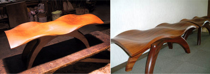
The photograph on the right of Fig. 4.12 shows the surface after the sanding process. The surface felt very satisfactory when touched with both the fingers and the palm. Undesirable cusp marks were not observed at all. Moreover, there was no over-sanding around the edge of the workpiece and no swell on the surface. Furthermore, we conducted a quantitative evaluation using a stylus instrument, so that the measurements obtained by the arithmetical mean roughness (Ra) and max height (Ry) were around 1 μm and 3 μm, respectively. Figure 4.13 shows a piece of new artistic furniture using the workpiece sanded by the robot sander. It was confirmed from the experimental result that the proposed robotic sanding system could successfully sand wooden workpieces with curved surfaces.
4.10 Conclusion
This chapter has dealt with a robotic sanding system for attractively designed furniture with free-formed surfaces. The system has been developed using an industrial robot with an open-architecture controller. The system has two novel features. One is that the surface-following controller developed for robotic sanding allows the robot to simultaneously realize a delicate polishing force control and smooth position/orientation control. The other is that conventional and complicated teaching task is not required at all. When conventional sanding systems based on an industrial robot are used, the desired trajectory for a tool’s position/orientation control is obtained through a complicated teaching process. In this case, the operator has to input a large number of teaching points along the object’s surface. However, the proposed robot sander directly handles CL data generated from the 3D CAD/CAM, so that this teaching process can be omitted. Experimentally, the sanding tool attached to the tip of the robot arm could smoothly follow the curved surface, keeping a contact from the normal direction with a desired polishing force. It was also demonstrated that the proposed system could successfully sand the curved surface of attractive furniture, resulting in very high-quality products.
The process parameters such as sanding conditions and control gains given in the experiments were tuned with trial and error in consideration of efficiency and sanded surface quality, and worked well for the examples shown in this paper. However, if the robot sander is applied to different materials, desirable parameters (i.e., semi-optimized parameters) should be found again, because the desirable parameters tend largely to depend on the type of wood. In the future, we plan to accumulate a database that has promising relations between the type of wooden material and desirable parameters. Although the parameters should be further tuned time-varyingly and delicately in compliance with intra-species variations as well as directionality and changes in a single workpiece, no practical on-line assessment techniques for wooden materials seem to be being proposed at this stage.
References
[1] Chen, C., Trivedi, M.M., Bidlack, C.R. Simulation and animation of sensor-driven robots. IEEE Trans. on Robotics and Automation. 1994; 10(5):684–704.
[2] Benimeli, F., Mata, V., Valero, F. A comparison between direct and indirect dynamic parameter identification methods in industrial robots. Robotica. 2006; 24(5):579–590.
[3] Corke, P. A Robotics Toolbox for MATLAB. IEEE Robotics & Automation Magazine. 1996; 3(1):24–32.
[4] Corke, P. MATLAB Toolboxes: robotics and vision for students and teachers. IEEE Robotics & Automation Magazine. 2007; 14(4):16–17.
[5] Luh, J.Y.S., Walker, M.H., Paul, R.P.C. Resolved acceleration control of mechanical manipulator. IEEE Trans. on Automatic Control. 1980; 25(3):468–474.
[6] Nagata, F., Kuribayashi, K., Kiguchi, K., Watanabe, K. Simulation of fine gain tuning using genetic algorithms for model-based robotic servo controllers. IEEE International Symposium on Computational Intelligence in Robotics and Automation. (196–201):2007.
[7] Nagata, F., Okabayashi, I., Matsuno, M., Utsumi, T., Kuribayashi, K., Watanabe, K., Fine gain tuning for model-based robotic servo controllers using genetic algorithms. 13th International Conference on Advanced Robotics. 2007:987–992.
[8] Hogan, N. Impedance control: An approach to manipulation: Part I - Part III. Transactions of the ASME, Journal of Dynamic Systems, Measurement and Control. 1985; 107:1–24.
[9] Nagata, F., Watanabe, K., Hashino, S., Tanaka, H., Matsuyama, T., Hara, K., Polishing robot using a joystick controlled teaching system. IEEE International Conference on Industrial Electronics, Control and Instrumentation. 2000:632–637.
[10] Craig, J.J. Introduction to ROBOTICS —Mechanics and Control Second Edition—. Addison Wesley Publishing Co., Reading, Mass; 1989.
[11] Nagata, F., Kusumoto, Y., Fujimoto, Y., Watanabe, K. Robotic sanding system for new designed furniture with free-formed surface. Robotics and Computer-Integrated Manufacturing. 2007; 23(4):371–379.
[12] Kawato, M. The feedback-error-learning neural network for supervised motor learning. In: Advanced Neural Computers. Elsevier Amsterdam; 1990:365–373.
[13] Nakanishi, J., Schaal, S. Feedback error learning and nonlinear adaptive control. Neural Networks. 2004; 17(10):1453–1465.
[14] Furuhashi, T., Nakaoka, K., Maeda, H., Uchikawa, Y. A proposal of genetic algorithm with a local improvement mechanism and finding of fuzzy rules. Journal of Japan Society for Fuzzy Theory and Systems. 1995; 7(5):978–987. [(in Japanese)].
[15] Linkens, D.A., Nyongesa, H.O. Genetic algorithms for fuzzy control part 1: Offline system development and application. IEE Proceedings Control Theory and Applications. 1995; 142(3):161–176.
[16] Linkens, D.A., Nyongesa, H.O. Genetic algorithms for fuzzy control part 2: Online System Development and Application. IEE Proceedings Control Theory and Applications. 1995; 142(3):177–185.
[17] Ferretti, G., Magnani, G., Zavala Rio, A. Impact modeling and control for industrial manipulators. IEEE Control Systems Magazine. 1998; 18(4):65–71.
[18] Sasaki, T., Tachi, S. Contact stability analysis on some impedance control methods. Journal of the Robotics Society of Japan. 1994; 12(3):489–496. [(in Japanese)].
[19] An, H.C., Hollerbach, J.M., Dynamic stability issues in force control of manipulators. IEEE International Conference on Robotics and Automation. 1987:890–896.
[20] An, H.C., Atkeson, C.G., Hollerbach, J.M., Model-based control of a robot manipulatorThe MIT Press classics series. Massachusetts: The MIT Press, 1988.
[21] Takagi, T., Sugeno, M. Fuzzy identification of systems and its applications to modeling and control. IEEE Transactions Systems, Man & Cybernetics. 1985; 15(1):116–132.
[22] Nagata, F., Watanabe, K., Sato, K., Izumi, K., An experiment on profiling task with impedance controlled manipulator using cutter location data. IEEE International Conference on Systems, Man, and Cybernetics. 1999:848–853.
[23] Nagata, F., Watanabe, K., Izumi, K., Furniture polishing robot using a trajectory generator based on cutter location data. IEEE International Conference on Robotics and Automation. 2001:319–324.
[24] Raibert, M.H., Craig, J.J. Hybrid position/force control of manipulators. Transactions of the ASME, Journal of Dynamic Systems, Measurement and Control. 1981; 102:126–133.
[25] Nagata, F., Hase, T., Haga, Z., Omoto, M., Watanabe, K. CAD/CAM-based position/force controller for a mold polishing robot. Mechatronics. 2007; 17(4/5):207–216.
[26] Nagata, F., Watanabe, K., Hashino, S., Tanaka, H., Matsuyama, T., Hara, K. Polishing robot using joystick controlled teaching. Journal of Robotics and Mechatronics. 2001; 13(5):517–525.
[27] Nagata, F., Watanabe, K., Kiguchi, K. Joystick teaching system for industrial robots using fuzzy compliance control. Industrial Robotics: Theory, Modelling and Control, INTECH, pages. (799–812):2006.
[28] Maeda, Y., Ishido, N., Kikuchi, H., Arai, T., Teaching of grasp/graspless manipulation for industrial robots by human demonstration. IEEE/RSJ International Conference on Intelligent Robots and Systems. 2002:1523–1528.
[29] Kushida, D., Nakamura, M., Goto, S., Kyura, N. Human direct teaching of industrial articulated robot arms based on force-free control. Artificial Life and Robotics. 2001; 5(1):26–32.
[30] Sugita, S., Itaya, T., Takeuchi, Y. Development of robot teaching support devices to automate deburring and finishing works in casting. The International Journal of Advanced Manufacturing Technology. 2003; 23(3/4):183–189.
[31] Ahn, C.K., Lee, M.C., An off-line automatic teaching by vision information for robotic assembly task. IEEE International Conference on Industrial Electronics, Control and Instrumentation. 2000:2171–2176.
[32] Neto, P., Pires, J.N., Moreira, A.P., CAD-based offline robot programming. IEEE International Conference on Robotics Automation and Mechatronics. 2010:516–521.
[33] Ge, D.F., Takeuchi, Y., Asakawa, N. Automation of polishing work by an industrial robot, – 2nd report, automatic generation of collision-free polishing path –. Transaction of the Japan Society of Mechanical Engineers. 1993; 59(561):1574–1580. [(in Japanese)].
[34] Ozaki, F., Jinno, M., Yoshimi, T., Tatsuno, K., Takahashi, M., Kanda, M., Tamada, Y., Nagataki, S. A force controlled finishing robot system with a task-directed robot language. Journal of Robotics and Mechatronics. 1995; 7(5):383–388.
[35] Pfeiffer, F., Bremer, H., Figueiredo, J. Surface polishing with flexible link manipulators. European Journal of Mechanics, A/Solids. 1996; 15(1):137–153.
[36] Takeuchi, Y., Ge, D., Asakawa, N., Automated polishing process with a human-like dexterous robot. IEEE International Conference on Robotics and Automation. 1993:950–956.
[37] Pagilla, P.R., Yu, B. Robotic surface finishing processes: modeling, control, and experiments. Transactions of the ASME, Journal of Dynamic Systems, Measurement and Control. 2001; 123:93–102.
[38] Huang, H., Zhou, L., Chen, X.Q., Gong, Z.M. SMART robotic system for 3D profile turbine vane airfoil repair. International Journal of Advanced Manufacturing Technology. 2003; 21(4):275–283.
[39] Stephien, T.M., Sweet, L.M., Good, M.C., Tomizuka, M. Control of tool/workpiece contact force with application to robotic deburring. IEEE Journal of Robotics and Automation. 1987; 3(1):7–18.
[40] Kazerooni, H. Robotic deburring of two-dimensional parts with unknown geometry. Journal of Manufacturing Systems. 1988; 7(4):329–338.
[41] Her, M.G., Kazerooni, H. Automated robotic deburring of parts using compliance control. Transactions of the ASME, Journal of Dynamic Systems, Measurement and Control. 1991; 113:60–66.
[42] Bone, G.M., Elbestawi, M.A., Lingarkar, R., Liu, L. Force control of robotic deburring. Transactions of the ASME, Journal of Dynamic Systems, Measurement and Control. 1991; 113:395–400.
[43] Gorinevsky, D.M., Formalsky, A.M., Schneider, A.Y. Force Control of Robotics Systems. New York: CRC Press; 1997.
[44] Takahashi, K., Aoyagi, S., Takano, M., Study on a fast profiling task of a robot with force control using feedforward of predicted contact position data. 4th Japan-France Congress & 2nd Asia-Europe Congress on Mechatronics. 1998:398–401.
[45] Takeuchi, Y., Watanabe, T. Study on post-processor for 5-axis control machining. Journal of the Japan Society for Precision Engineering. 1992; 58(9):1586–1592. [(in Japanese)].
[46] Takeuchi, Y., Wada, K., Hisaki, T., Yokoyama, M. Study on post-processor for 5-axis control machining centers —In case of spindle-tilting type and table/spindle-tilting type. Journal of the Japan Society for Precision Engineering. 1994; 60(1):75–79. [(in Japanese)].
[47] Xu, X.J., Bradley, C., Zhang, Y.F., Loh, H.T., Wong, Y.S. Tool-path generation for five-axis machining of free-form surfaces based on accessibility analysis. International Journal of Production Research. 2002; 40(14):3253–3274.
[48] Chen, S.L., Chang, T.H., Inasaki, I., Liu, Y.C. Postprocessor development of a hybrid TRR-XY parallel kinematic machine tool. The International Journal of Advanced Manufacturing Technology. 2002; 20(4):259–269.
[49] Lei, W.T., Hsu, Y.Y. Accuracy test of five-axis CNC machine tool with 3D probe-ball Part I: design and modeling. Machine Tool & Manufacture. 2002; 42(10):1153–1162.
[50] Lei, W.T., Sung, M.P., Liu, W.L., Chuang, Y.C. Double ballbar test for the rotary axes of five-axis CNC machine tools. Machine Tool & Manufacture. 2006; 47(2):273–285.
[51] Cao, L.X., Gong, H., Liu, J. The offset approach of machining free form surface. Part 1: Cylindrical cutter in five-axis NC machine tools. Journal of Materials Processing Technology. 2006; 174(1/3):298–304.
[52] Cao, L.X., Gong, H., Liu, J. The offset approach of machining free form surface. Part 2: Toroidal cutter in 5-axis NC machine tools. Journal of Materials Processing Technology. 2007; 184(1/3):6–11.
[53] Timar, S.D., Farouki, R.T., Smith, T.S., Boyadjieff, C.L. Algorithms for time optimal control of CNC machines along curved tool paths. Robotics and Computer-Integrated Manufacturing. 2005; 21(1):37–53.
[54] Heo, E.Y., Kim, D.W., Kim, B.H., Chen, F.F. Estimation of NC machining time using NC block distribution for sculptured surface machining. Robotics and Computer-Integrated Manufacturing. 2006; 22(5–6):437–446.
[55] Tarng, Y.S., Chuang, H.Y., Hsu, W.T. Intelligent cross-coupled fuzzy feedrate controller design for CNC machine tools based on genetic algorithms. International Journal of Machine Tools and Manufacture. 1999; 39(10):1673–1692.
[56] Zuperl, U., Cus, F., Milfelner, M. Fuzzy control strategy for an adaptive force control in end-milling. Journal of Materials Processing Technology. 2005; 164/165:1472–1478.
[57] Farouki, R.T., Manjunathaiah, J., Nicholas, D., Yuan, G.F., Jee, S. Variable-feedrate CNC interpolators for constant material removal rates along Pythagorean-hodograph curves. Computer-Aided Design. 1998; 30(8):631–640.
[58] Farouki, R.T., Manjunathaiah, J., Yuan, G.F. G codes for the specification of Pythagorean-hodograph tool paths and associated feedrate functions on open-architecture CNC machines. Machine Tools & Manufacture. 1999; 39(1):123–142.
[59] Frank, A., Schmid, A. Grinding of non-circular contours on CNC cylindrical grinding machines. Robotics and Computer-Integrated Manufacturing. 1988; 4(1/2):211–218.
[60] Couey, J.A., Marsh, E.R., Knapp, B.R., Vallance, R.R. Monitoring force in precision cylindrical grinding. Precision Engineering. 2005; 29(3):307–314.
[61] Tawakoli, T., Rasifard, A., Rabiey, M. Highefficiency internal cylindrical grinding with a new kinematic. Machine Tools & Manufacture. 2007; 47(5):729–733.
[62] Nagata, F., Kusumoto, Y., Hasebe, K., Saito, K., Fukumoto, M., Watanabe, K., Post-processor using a fuzzy feed rate generator for multi-axis NC machine tools with a rotary unit. International Conference on Control, Automation and Systems. 2005:438–443.
[63] Nagata, F., Watanabe, K. Development of a postprocessor module of 5-axis control NC machine tool with tilting-head for woody furniture. Journal of the Japan Society for Precision Engineering. 1996; 62(8):1203–1207. [(in Japanese)].
[64] Fujino, K., Sawada, Y., Fujii, Y., Okumura, S., Machining of curved surface of wood by ball end mill – Effect of rake angle and feed speed on machined surface. 16th International Wood Machining Seminar, Part 2. 2003:532–538.
[65] Nagata, F., Hase, T., Haga, Z., Omoto, M., Watanabe, K., Intelligent desktop NC machine tool with compliance control capability. 13th International Symposium on Artificial Life and Robotics. 2008:779–782.
[66] Duffy, J. The Fallacy of modern hybrid control theory that is based on orthogonal complements of twist and wrench spaces. Journal of Robotic Systems. 1990; 7(2):139–144.
[67] Lee, M.C., Go, S.J., Lee, M.H., Jun, C.S., Kim, D.S., Cha, K.D., Ahn, J.H. A robust trajectory tracking control of a polishing robot system based on CAM data. Robotics and Computer-Integrated Manufacturing. 2001; 17(1/2):177–183.
[68] Nagata, F., Mizobuchi, T., Tani, S., Hase, T., Haga, Z., Watanabe, K., Habib, M.K., Kiguchi, K., Desktop orthogonal-type robot with abilities of compliant motion and stick-slip motion for lapping of LED lens molds. IEEE International Conference on Robotics & Automation. 2010:2095–2100.
[69] Bilkay, O., Anlagan, O. Computer simulation of stick-slip motion in machine tool slideways. Tribology International. 2004; 37(4):347–351.
[70] Mei, X., Tsutsumi, M., Tao, T., Sun, N. Study on the compensation of error by stick-slip for high-precision table. International Journal of Machine tools & Manufacture. 2004; 44(5):503–510.
[71] Tsai, M.J., Chang, J.L., Haung, J.F., Development of an automatic mold polishing system. IEEE International Conference on Robotics & Automation. 2003:3517–3522.
[72] Tsai, M.J., Fang, J.J., Chang, J.L. Robotic path planning for an automatic mold polishing system. International Journal of Robotics & Automation. 2004; 19(2):81–89.
[73] Hocheng, H., Sun, Y.H., Lin, S.C., Kao, P.S. A material removal analysis of electrochemical machining using flat-end cathode. Journal of Materials Processing Technology. 2003; 140(1/3):264–268.
[74] Uehara, Y., Ohmori, H., Lin, W., Ueno, Y., Naruse, T., Mitsuishi, N., Ishikawa, S., Miura, T., Development of spherical lens ELID grinding system by desk-top 4-axes Machine Tool. International Conference on Leading Edge Manufacturing in 21st Century. 2005:247–252.
[75] Ohmori, H., Uehara, Y. Development of a desktop machine tool for mirror surface grinding. International Journal of Automation Technology. 2010; 4(2):88–96.
[76] Nagata, F., Hase, T., Haga, Z., Omoto, M., Watanabe, K. Intelligent desktop NC machine tool with compliant motion capability. Artificial Life and Robotics. 2009; 13(2):423–427.
[77] Nagata, F., Tani, S., Mizobuchi, T., Hase, T., Haga, Z., Omoto, M., Watanabe, K., Habib, M.K., Basic performance of a desktop NC machine tool with compliant motion capability. IEEE International Conference on Mechatronics and Automation, WC1-5. 2008:1–6.
[78] Nagata, F., Watanabe, K., Sato, K., Izumi, K. Impedance control using anisotropic fuzzy environment models. Journal of Robotics and Mechatronics. 1999; 11(1):60–66.
[79] Nagata, F., Otsuka, A., Yoshitake, S., Watanabe, K., Automatic control of an orthogonal-type robot with a force sensor and a small force input device. The 37th Annual Conference of the IEEE Industrial Electronics Society. 2011:3151–3156.
[80] Nagata, F., Watanabe, K. Feed rate control using a fuzzy reasoning for a mold polishing robot. Journal of Robotics and Mechatronics. 2006; 18(1):76–82.
[81] Nagata, F., Watanabe, K., Japanese Patent 4094781, Robotic force control method, 2008.
[82] Nagata, F., Tsuda, K., Watanabe, K., Japanese Patent 4447746, Robotic trajectory teaching method, 2010.
[83] Tsuda, K., Yasuda, K., Nagata, F., Kusumoto, Y., Watanabe, K., Japanese Patent 4216557, Polishing apparatus and polishing method, 2008.