
Guest Chapter by Madeline Gannon
We have a long tradition—as old as human civilization itself—of crafting wearable garments and objects for the body. But it is only in the past 30 or 40 years that we have been building tools to digitize these traditionally analog practices. Although we shouldn’t reject millennia of accumulated knowledge, handcrafted design processes have certain limitations that digital tools can help overcome. For example, when designing wearables that need to be custom-fitted to the body, such as prosthetics or masks, a design for one person is not easily adaptable to another; this creates a lot of redundant work when it’s time to scale up production. In addition, pragmatic functions—like archiving, editing, sharing, and duplicating a wearable—are hard to do with analog design workflows. Computer-Aided Design (CAD) software, however, is incredibly useful for these processes.
This chapter goes over the benefits of using design software and highlights commonly used tool sets for digitally designing wearables. It touches on designing for fabrication and shows you ways to tailor your digital tools for more customized workflows in wearable design. If you are new to digital processes like 3D modeling, 3D scanning, and parametric modeling, keep in mind that there is a learning curve. But with a bit of patience and perseverance, integrating digital tools into your design process will enhance both your efficiency and your creativity.
Software for Digital Design
CAD tools—software for digital design—fall into two primary categories: tools for designing in two dimensions and tools for designing in three dimensions. If you are new to digital design processes, you may want to start by experimenting with two-dimensional CAD tools; these tend to be easier to learn, and they pair nicely with 2D fabrication processes. For those diving into 3D-modeling and 3D-printing wearables, this chapter has suggestions for choosing the right software for your design needs. A nearly endless number of CAD tools are available, but this section highlights specific examples that are most useful for designing and producing wearables.
2D Design Tools
The design and fabrication of clothing has traditionally existed as a two-dimensional process: you use 2D templates to cut out a design from a 2D sheet of fabric, which you then sew into the three-dimensional garment. Although it is perfectly adequate to do this process by hand, you can also use software to assist in the creation and execution of your design.
Graphic design software like Adobe Illustrator and CorelDRAW, and CAD software like AutoCAD and Vectorworks, provide digital canvases for drawing 2D patterns and designs. Most important, these software packages (and many others) can export your design as a vector graphic, which can be sent to a fabrication machine. Vector graphics are a way of representing a digital image as a series of 2D (x,y) coordinates plotted on the screen. Because the digital image is represented as coordinates and not pixels, you can send vector graphics to all sorts of two-axes digital fabrication machines, including laser cutters, vinyl cutters, and more traditional paper printers and plotters. The next chapter goes over digital fabrication tools in more detail, but keep this in mind: if your software can export a design as a file type with the extension .dxf, .dwg, .ai, or .pdf, chances are you can send your 2D digital design to a fabrication machine.
3D Design Tools
3D modeling is a more recent addition to the wearable designer’s repertoire. Commercially available software for 3D modeling is tailored toward three distinct domains: product design, computer graphics and animation, and architectural design. Notice anything missing? Currently there are no 3D-modeling tools designed specifically for fashion design or wearable design! The next section addresses this limitation; for now, let’s find the best available option for the type of wearables you’ll be designing.
Choosing the Right Modeling Software
Learning to 3D-model can be technically challenging and time consuming. To make things even more difficult, each 3D design tool brings its own strengths and weaknesses when it comes to geometric representation, usability, and cost. This makes learning multiple programs difficult, so it’s best to start with the design tool best suited to your needs.
If you use geometric representation as a guiding criterion, designers creating wearables that are more closely related to product design, such as medical devices or shoes, should use solid modeling software. Examples of solid modelers include Dassault Systèmes SOLIDWORKS, Autodesk Fusion 360, and OpenSCAD. Designers creating wearables with more free-flowing, organic forms should use software that’s more tailored for computer graphics, animation, and architectural design, such as Rhinoceros 3D, Blender, or Autodesk Maya.
If you use usability and cost as the guiding criteria, Blender and OpenSCAD are free, open source programs with vibrant developer communities. Autodesk products have free student software licenses, but professional licenses are costly. Rhinoceros 3D is perhaps the easiest to learn and the most extensible through its Grasshopper plug-in. Maya is perhaps the most difficult to learn, but it is also the most powerful in terms of 3D modeling.
Finally, the most tried-and-true method for choosing the right design tool for your needs is to first find work that you admire and then contact the creator to inquire about their digital design tools and workflows.
3D Modeling for 3D Printing
3D modeling can be used in every phase when designing a wearable: in the concept phase for rendering images; in the development phase for rapid prototyping and 3D printing; and in the production phase for preparing for mass production processes, like injection molding. However, the constraints and requirements of a 3D model change for each of these phases. For example, a 3D model created to look its best in a rendering may not be built properly for 3D printing. This section focuses on 3D modeling for rapid prototyping and looks specifically at how to 3D-model for 3D printing.
A 3D model needs to satisfy three basic requirements before it can be printed:
The geometry must be a closed solid or a closed mesh.
The geometry cannot have self-intersecting faces.
The geometry must match the minimum resolution of a printer.
For a 3D model to be a closed solid or a closed mesh, all the faces must be joined together such that there are no holes in the mesh. Another way people describe this property is that the 3D model needs to be watertight. Imagine you poured water into your 3D model: would water leak out? If so, then your model has a hole that needs closing. Figure 8-1 shows a valid, closed solid model compared to an invalid 3D model with a hole.

Figure 8-1. The 3D model on the left shows a closed solid model, but the model on the right has a hole in its hexagonal cutout. This hole violates the watertight principle, which makes the model invalid for 3D printing
3D geometry has both an inside and an outside. The mesh is self-intersecting when the inside of the mesh gets flipped outside. In Figure 8-2, the inside of each mesh face is colored magenta. You can tell when a 3D model is turned inside-out when these inverted magenta faces show on the outside of the 3D surface. Figure 8-2 shows a valid mesh compared to one with inverted faces.

Figure 8-2. The 3D model on the left shows a closed solid model, but the model on the right has inverted faces in its hexagonal cutout. These inside-out faces violate the self-intersecting principle, which makes the model invalid for 3D printing
When 3D modeling for 3D printing, it’s important to design for the minimum print resolution of your 3D printer. The print resolution of a 3D printer is the minimum size for any geometry to be printed. If you design a 3D model with features that are smaller than the minimum resolution of a printer, then those features are too small for the 3D printer to realize. Moreover, different 3D printers have different print resolutions: a standard FDM desktop 3D printer may have a print resolution of around .1 mm, whereas a higher-end SLA printer may have a resolution of 10 microns! Figure 8-3 shows a bracelet that failed during 3D printing because details in the 3D model were below the minimum print resolution of the 3D printer.
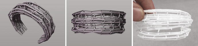
Figure 8-3. This sequence of images shows a digital design with the corresponding physical print. A 3D print can fail or break when the 3D model has details that are below the print resolution of the 3D printer
Customizing Your Tools
As previously mentioned, currently available 3D-modeling software is not built specifically for digitally crafting wearables; it is most commonly used for architectural, aeronautical, automotive, and product design applications. However, designing for the body has different challenges than designing a building, a boat, a car, or a gadget.
Human bodies are highly complex, highly specific physical contexts; 3D-modeling tools tend to be empty virtual spaces that ignore physical contexts. This can make it difficult to digitally design wearables that have a tailored or ergonomic fit. Moreover, every body is different; creating variations of a design for multiple body types can be a laborious task in current 3D-modeling software. Modifying a design to work for S, M, L, and XL sizes is not as simple as scaling a 3D model up or down.
This section looks at two strategies for customizing your 3D-modeling tools to circumvent these limitations. First, you see techniques to digitize the body—bringing a digital reference of the physical body into a virtual modeling environment. Next you learn about parametric modeling techniques—a way to rapidly iterate and build variation into a digital design. Integrating these two strategies into your 3D-modeling workflow helps to customize your tools so you can tackle the more difficult challenges for digitally designing wearables.
Digitizing the Body
Bringing a digital reference of a body into your 3D-modeling tool is one useful technique for 3D-modeling wearables. Although some modeling software has default human bodies that you can directly import into the 3D-modeling environment, these tend to be idealized forms that are mainly used as scale figures for a 3D-modeled scene. To get a more accurate representation of a body, you can digitize—or 3D scan—a person’s body. 3D scanningis a process of digitally capturing the body using hardware and then using software to process and reconstruct the captured data into a 3D mesh. This mesh can then be imported into your 3D-modeling environment.
Central to 3D scanning is the idea of resolution. The resolution of a 3D scan is the amount of detail and geometric fidelity it has to the physical counterpart: low-resolution scans have a low amount of detail, and high-resolution scans have a high amount of detail. It’s important to find the right resolution for digitizing the body: if you have too little detail in your 3D scan, a design may not accurately fit the body; if you have too much detail in your 3D scan, the file size of your 3D model may be too big for your modeling software to process. Figure 8-4 shows a full-body 3D scan that has been resampled at different resolutions.

Figure 8-4. A full-body 3D scan that has been resampled to four different resolutions. The scan with the highest resolution (densest number of mesh faces) is in the background, and the scan with the lowest resolution (sparsest number of mesh faces) is in the foreground
The three most useful 3D-scanning techniques for digitizing the body are photogrammetry, depth cameras, and structured light scanning. The process of 3D scanning may seem technologically complex, but there are a number of options with a low point of entry to get you started. For example, instead of purchasing expensive 3D-scanning hardware, you can use your smartphone camera, an inexpensive depth camera like the Microsoft Kinect, or a projector and camera to 3D-scan the body. The following sections go into detail about the advantages and limitations of each of these three digitizing techniques.
Photogrammetry
Photogrammetryis a 3D-scanning process that stitches together photographs to create a fully three-dimensional model. It works by taking a lot of photos of an object from every possible angle. The photogrammetry software then reconstructs a 3D object from these 2D images by analyzing slight differences in the light reflected off the object in each photograph.
Although these software algorithms are quite sophisticated, photogrammetry is an easy and affordable way to 3D-scan something. It requires a little planning but no special hardware. All you need is a decent cell phone camera to get started: the algorithms handle all the complicated model reconstruction, and you get back a fairly accurate digital representation of your physical capture. Figure 8-5 shows the resulting capture session from one photogrammetry app, 123D Catch. Notice how, given a set of photographs, the software is able to estimate the world position of the camera.
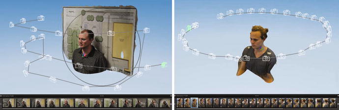
Figure 8-5. These two screenshots show how photogrammetry software, like Autodesk’s 123D Catch, constructs a 3D model from a set of photographs. (Screen captures from www.instructables.com/id/3D-Printing-your-own-full-color-bobblehead-using-1 .)
However, there are limitations. Photogrammetry algorithms look for minute changes across a large set of images, so they are very sensitive to environmental changes such as moving capture subjects or changes in lighting. Moreover, captured images need a decent amount of overlap to fully reconstruct a 3D object. This works well for small to medium-sized objects, like a toy or a vase, but can be difficult for large objects, like a human body. Also, this need for overlapping images makes it difficult to adequately capture areas with large amounts of three-dimensional change, such as hands or fingers.
For the best results, keep these requirements in mind when using photogrammetry to 3D-scan the body:
The person being captured must remain very still.
The lighting in the space where you doing the capture must remain very consistent.
The images being captured must significantly overlap. Plan your capture session to reach difficult areas of the body, like the top of the head and the hands and arms.
Many programs and apps use photogrammetry for 3D scanning, but the two I recommend starting with are Autodesk’s 123D Catch (free) and Agisoft’s PhotoScan (free 30-day trial).
Depth Cameras
Depth cameras use various hardware and software configurations to sense the three-dimensional world, but all they follow a similar technique: project infrared (IR) light out into an environment and then sense where or when the IR light hits a surface. Depth cameras use IR light because it is invisible to the human eye: a depth camera can beam high densities of information into an environment, and you and I are none the wiser. Depth cameras reconstruct this information as depth maps, point clouds, or meshes. Figure 8-6 shows examples of point clouds captured by a Microsoft Kinect.
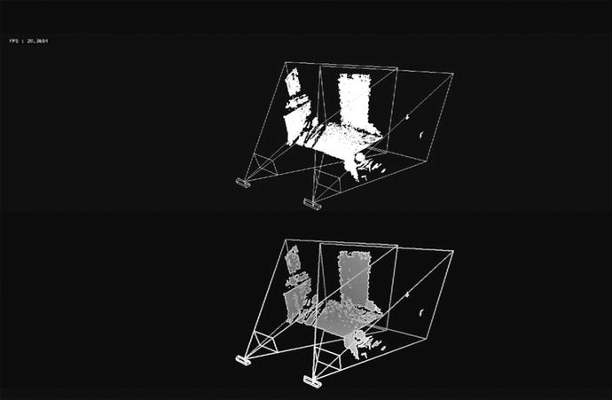
Figure 8-6. Point clouds from a Microsoft Kinect. This raw data can be processed into refined 3D meshes using various optimization algorithms
Different depth cameras have different resolutions (the amount of detail they can sense): low-resolution depth cameras, such as the Microsoft Kinect, tend to be cheaper, whereas high-resolution cameras, like Artec 3D hand-held scanners, tend to be more expensive and used for more specialized purposes.
3D scanning with depth cameras takes more time to master than photogrammetry, where you can use an app on your smartphone to start 3D scanning. However, depth cameras have distinct advantages that can be worth the time and monetary investment. For one thing, depth cameras are very resilient to changing lighting conditions in your capture environment. Unlike photogrammetry, these cameras use IR light, not visible light, to sense the world: if the environmental light changes in the middle of your scanning session, it won’t be sensed by the depth camera, and your scan won’t be ruined. With depth cameras, you can even 3D-scan a subject in a completely dark environment!
Depth cameras are also flexible and useful devices for analyzing the body. Yes, you can use them to create a static 3D scan, but you can also use depth cameras to dynamically sense how the body is moving. They give you the ability to detect and track different movements, interactions, and gestures for one or more bodies. Access to this real-time data can be invaluable when designing wearables for parts of the body that are constantly moving, like shoes and medical braces.
One of the limitations of depth cameras is that they can’t scan objects or surfaces that are reflective or refractive. Depth cameras work by projecting and then sensing IR light; if you try to scan a reflective surface, like a mirror, the projected beams of IR light bounce away from the camera’s IR sensor. If the projected light never returns to the sensor, then the camera can’t read in the depth data. When using depth cameras to digitize the human body, this issue comes up most often when the person being scanned is wearing reflective jewelry, a watch, or glasses; but even a person with very oily or sweaty/wet skin can corrupt scan data. This can leave noticeable holes in your scan data.
Structured Light Scanning
Structured light scanning works similarly to 3D scanning with depth cameras: you project light into an environment and then sense how that light hits a surface. However, instead of using infrared light that you can’t see, structured light scanning uses a standard projector and camera. Three-phase structured light scanning works by projected three specifically patterned calibration images onto the capture subject. Figure 8-7 shows how these 2D patterns deform when projected onto the capture subject and then generate the 3D scan.


Figure 8-7. Three-phase structured light scanning can be an economical way to get high-resolution 3D scans . The top row shows the three calibration images for three-phase scanning. The bottom row shows the calibration images projected onto a car seat and the resulting digitized surface; note the high level of detail in the wrinkles of the leather seat. (Images courtesy Wikimedia Commons, licensed under CC BY 3.0.)
This sounds quite complicated—and it is—but basic structured light scanning is a very inexpensive way to get high-resolution 3D scans. All you need is a projector, a camera, and some smart software. There are open source software options, if you would like to try it yourself. I recommend this tutorial from MIT: http://fab.cba.mit.edu/content/processes/structured_light .
You will most commonly find structured light scanning being used to capture the bodies of actors for films. In this scenario, highly specialized stages filled with DSLR cameras and programmable LED lights sequentially bounce light off the capture subject. One spectacular example is Light Stage V from the University of Southern California’s Institute for Creative Technologies. Light Stage V is a geodesic dome with 156 programmable LED lights. As the LED lights are sequenced on and off, a high-speed camera captures the light bouncing off the capture subject at 24 times per second. A high-speed structured light projector adds dynamic geometry information onto this reflectance data. What results is an extremely high-detail 3D scan—down to the pores of the skin. For more technical details and images, see http://gl.ict.usc.edu/Research/DigitalEmily/ .
Table 8-1 summarizes this section in a simple, easy-to-read form. As you decide which digitizing technique to use, keep in mind the constraints of your capture subject, capture environment, and project budget.
Table 8-1. Summary of the Benefits and Tradeoffs for Each Technique That Digitizes the Body
Technique | Pros | Cons | Level |
|---|---|---|---|
Photogrammetry | Easy to learn and use Inexpensive Can capture full 3D objects | Subjects must remain very still Lighting must remain very consistent Not good for capturing details like hands or fingers | Beginner |
Depth camera | Scan quality independent of lighting conditions Many moderately priced hardware solutions | Not good for capturing reflective surfaces | Intermediate |
Structured light | Extremely high-detail scans | Expensive, large setup Complex software solutions | Advanced |
Case Study: Open Fit Lab
One great example of how digitizing the body can change the way you design and construct wearables is the Open Fit Lab. The Open Fit Lab is an initiative by Lisa Kori Chung and Kyle McDonald to bring new software techniques to traditional clothing construction. In this case, they are using a depth camera and custom software to automatically generate patterns for tailored pants.
To create these digital pants patterns, the Open Fit software uses a Microsoft Kinect to scan a person’s legs and extract specific body dimensions. These dimensions, such the crotch length, hip-to-floor height, and thigh, calf, and ankle widths, then update a generic pants pattern to fit this specific body. The newly generated 2D pattern is projected onto a bolt a fabric, and tailors mark up, cut out, and sew together the customized pants. Figure 8-8 shows the process from software interface to physical fabrication.

Figure 8-8. The Open Fit workflow begins with a parametric pattern generator. The pattern generator is updated by real-time readings from a person’s body. The updated pattern is projected at a 1:1 scale onto fabric for final construction. (Images courtesy of Lisa Kori and Kyle McDonald, Open Fit Lab.)
The Open Fit workflow elegantly balances digital/physical processes in digitally generating patterns and facilitating analog fabrication. However, the digital workflow does not necessarily need to stop at the design phase: these digital patterns could also be cut using a 2D-fabrication machine. The digital files generated by the Open Fit software are the same kinds of files a laser cutter or CNC drag knife uses to cut out a design from fabric. Admittedly, this is not a necessary step. But it is a great example to illustrate how easily digital design and fabrication processes link together. As you are engulfed in the process of digital design, keep in mind how your digital design will eventually come out of the computer and into the physical world.
Parametric Design
Now that you have brought the human body as a digital canvas into your 3D modeling environment, you have a great starting point for designing wearables. But these modeling environments have one more limitation that can make your design and production processes cumbersome: 3D models are very hard to adapt.
When you digitally create a wearable design using existing CAD environments, it is 3D-modeled as a single, static object. However, wearables rarely ever exist as a single static version: a single design might need multiple formal adaptations to fit different body types, fabrication techniques, or even aesthetic sensibilities. This is where parametric design can help.
Parametric design is a technique for embedding variation directly into your design. One parametric object that you may encounter daily is the disposable coffee cup. This cup has fixed variables that don’t change, like the diameter of its top and bottom rims, and it has open variables that do change, such as its height and volume. The relationship between the height and volume of the coffee cup is its defining parameter. Changing one variable of a parameter affects the others: tweaking the height of the cup modifies the overall volume of coffee that it can hold, for example. With parametric modeling, the effort you put into building the original model gives you instant variation without the need to reconstruct any geometry. As in the cup example, the design effort to create a 12-ounce cup also lets you generate 16 oz cups, 20 oz cups, or even 23.57 oz cups.
For wearables, parametric modeling is exceptionally helpful for iterating, customizing, and personalizinga design. Basing the 3D model of a wearable on parameters lets you rapidly iterate through a wide range of options during the design phase. A designer can explore formal and functional changes just by tweaking a few variables. Figure 8-9 shows a parametric bracelet being modified by the designer. The parametric model is dynamically transformed by simply shifting the values of a few variables.
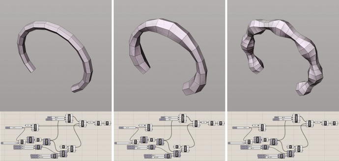
Figure 8-9. The design of this bracelet can be rapidly explored using parametric modeling. Just tweaking the radius and twist of each bracelet segment generates many variations on a single form
Once the design of a wearable is finalized, you can use the same techniques to customize and adapt the overall design to multiple body types. Figure 8-10 shows the parametric bracelet in a variety of sizes. Each variation keeps the same aesthetic and fabrication constraints of the original model but is sized to fit a different wrist diameter.
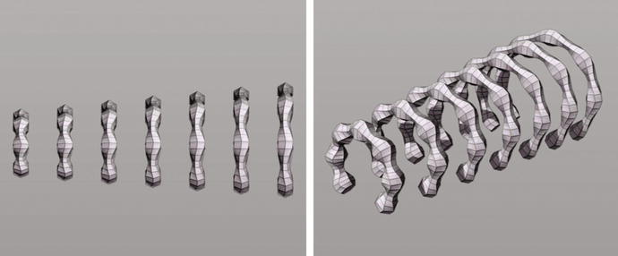
Figure 8-10. Adapting a wearable design to fit many body types is streamlined using parametric modeling techniques. When this example bracelet is sized up and down, the fabrication properties (such as wall thickness) are preserved
In the previous two examples, all the changes in the parametric model result from tweaking one or two numeric values. Parametric models abstract the formal behaviors of a design down to interdependent numbers. These numbers don’t need to be arbitrary values; they can be very specific data for personalizing a design to an individual. The bracelets in Figure 8-11, for example, are personalized with the individual’s Twitter data. The overall aesthetic, design, and fabrication constraints are consistent, but the data gathered from each individual person generates a unique form.
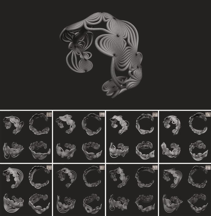
Figure 8-11. Parametric design also lets you personalize a design for an individual. These bracelets share aesthetic values but integrate an individual’s Twitter data to generate uniquely distinct forms
Tools for Parametric Modeling
Most 3D modeling environments use back-ends or plug-ins that support parametric design. They can be scripted (where you write code to build the model) or visual (where you construct code through a drag-and-drop interface). The principles behind both kinds are the same: they offer back-door access to the geometry functions that the program uses. Table 8-2 shows three of the most commonly used tools for parametric modeling in existing CAD software.
Table 8-2. Features of Three Parametric Modeling Tools
Interface | Modeling Software | Features |
|---|---|---|
Grasshopper | Rhinoceros 3D | Visual programming Language Easier to learn Helpful online community |
MEL Script | Maya 3D | Proprietary scripting language Access to powerful geometry and physics libraries |
Python | Blender 3D | Commonly used scripting language Free and open source Helpful online community |
If you have programming experience, you may feel most comfortable working with OpenSCAD, which is a code-based 3D modeling platform. But you can also build your own parametric modeling tool. Creative coding platforms, such as Processing and openFrameworks, offer many good libraries and resources for programming parametric forms. One benefit of building your own custom parametric modeling tool is that it gives you exceptional control over data integration, user interaction, and customization in your design. See the tutorial at https://github.com/madelinegannon/BodyArchitectures for a step-by-step walkthrough on how to make 3D-printed bracelets using Processing.
Summary
People are fairly particular about what they put on their bodies, so wearables have a demanding list of requirements they need to satisfy. To some degree, wearables need to be functional, beautiful, and comfortable. Adding to the complexity is that everyone’s body is different: a wearable that is comfortable for your body may not be for mine; one that is functional for mine may not be for yours. These requirements—or design constraints—are particularly challenging when digitally crafting wearables.
This chapter discussed commercially available software for creating 2D and 3D digital designs. It also highlighted current limitations for designing for the body. To overcome these limitations, you saw two techniques for customizing existing digital design tools. You learned about ways to bring in physical bodies as digital references in a virtual modeling environment and about principles of parametric design for designing wearables. You also saw how parametric modeling uses the full potential of digital design for wearables by letting designers rapidly explore a design space, customize a design, and integrate personalized data into the design of a wearable.
The next chapter goes over how to translate digital designs into physical artifacts using a variety of fabrication machines.