

Creating solution artifacts
This chapter describes the process of creating custom artifacts for the scenario described in 1.2, “The business scenario” on page 14. We describe the creation of web and mobile applications and the complete environments that support the scenario, including the integration layer with integration flows. For the web application, both the Liberty profile and the WebSphere Application Server full profile are discussed. As the foundation for the mobile application, we will be using IBM Worklight.
In this chapter, the following topics are discussed:
•5.4, “Prepare WebSphere Application Server full profile environment for web application” on page 136
5.1 Prepare the integration environment
In the overall solution, the integration environment plays a key role in enabling the components to communicate using their native mechanisms and protocols. The business scenario described in this book (see 1.2, “The business scenario” on page 14) is an example of the variety of commonly used technologies for communication. Follow this section for guidance in preparing and implementing the integration applications.
5.1.1 Integration architecture
Let us start by designing a solution for the scenario described in 1.2, “The business scenario” on page 14.
We described in 2.2, “Middleware products used for the solution” on page 20, that there will be two sources of incoming messages:
•One source will use the asynchronous method of delivering XML messages to the WebSphere MQ queue.
•One source will send a synchronous HTTP request with a JavaScript Object Notation (JSON) message.
The job of the IBM Integration Bus is to receive messages from both channels, persist in the database, and invoke a business event rule that will launch the business process.
This process can be split into three separate parts (three integration flows):
•The first integration flow listens for incoming XML messages to WebSphere MQ queue and processes the XML message.
•The second integration flow is invoked by an HTTP request and processes the JSON message. The result of both integration flows is then sent to an additional WebSphere MQ queue, which is not accessible by the external clients.
The messages that are put into this internal queue will trigger the third integration flow, for which the execution logic is common to all incoming messages.
•The third integration flow persists the data in the database, writes the event to a log file, and sends a SOAP request to trigger an event rule that is deployed on the IBM Operational Decision Manager.
This concept is depicted graphically in Figure 5-1 on page 115.

Figure 5-1 Integration flow concept for the business scenario
|
Tip: There are three primary reasons for using the additional integration flow with an internal queue, rather than creating two integration flows for each input:
•The common logic that triggers the same service is implemented only one time.
•Improved performance. With this approach, the work done by the Integration Bus is paralyzed, and more threads are involved in running the integration flows. This is also the reason why subflows were not used, as subflows are a logical extension of the integration flows.
•Better control over the integration process. With this design, it is possible to stop a single channel to block requests from mobile devices, or to stop the triggering flow in the case of a maintenance window (for example, administrative maintenance) that has to be done from the business process side. From the client’s perspective, the solution is continuously available; however, invisible to the user is that the solution queues messages and processes them when the stopped integration flow becomes operational again.
|
Next, we guide you through the steps for completing the integration solution.
5.1.2 Installation
The Integration Bus consists of the following components:
•IBM Integration Bus runtime: This is where the integration logic executes.
•WebSphere MQ: This component is closely tied with Integration Bus and is used in internal processing to allow parallel execution of threads. It installs on the same system as the IBM Integration Bus runtime.
•Integration Bus Toolkit: Eclipse-based tool that allows to design and implement the integration flows. It can be installed on the same system with the Integration Bus or it can connect to remote Integration Bus server. It is not required to run applications on Integration Bus.
•Integration Explorer: This is a WebSphere MQ, Eclipse-based tool for use by administrators, enabling them to perform most administrative tasks and to monitor the Integration Bus runtime. Like the Integration Bus Toolkit, Integration Explorer operates with local and remote runtimes.
Follow the IBM Knowledge Center installation guide for Integration Bus installation details and prerequisites. See the IBM Knowledge Center:
In our scenario, we used Integration Bus Advanced version 9.
|
Note: Integration Bus version 9 is the successor to the WebSphere Message Broker. The Integration Bus shares many features with WebSphere Message Broker, and some of the commands still refer to the old product name.
For the latest details, refer to the IBM Integration Bus technical overview in the IBM Knowledge Center:
|
5.1.3 Configuration
With the Integration Bus runtime installed, follow these steps to begin developing the integration flows.
Create the Integration Bus instance
To create the Integration Bus instance, run the command:
mqsicreatebroker IB9NODE -q IB9QMGR -t
This command first checks to determine if there is an IB9QMGR defined in the system. If not, it is created, along with the necessary resources, such as internal queues that the Integration Bus requires to operate. This command produces the IB9NODE instance.
|
Note: The behavior of the mqsicreatebroker might vary for different platforms. Refer to the IBM Knowledge Center for detailed information about its behavior on your system and the default settings it uses:
|
Create the integration server
To create the integration server, follow these steps:
1. Start the Integration Bus instance, along with the WebSphere MQ queue manager by issuing the mqsistart command. This command performs initial verification tests, then starts the Integration Bus and its WebSphere MQ queue manager:
mqsistart IB9NODE
2. With the Integration Bus running, prepare an integration server, which is a configurable runtime environment in which the integration flows are being executed. Integration servers (named execution groups in the previous WebSphere Message Broker product) can be, for example, configured with separate listener ports or connection pool settings, which allows for sharing or separating of application resources in the Integration Bus.
3. Create the default integration server by issuing the following command on the system on which you installed the Integration Bus runtime environment:
mqsicreateexecutiongroup -i localhost -p 1414 -q IB9QMGR -e default
|
Note: You can also create the integration server, and many other configurations, using the Integration Bus Toolkit or the Integration Explorer graphical interface. Refer to the IBM Knowledge Center for instructions and examples:
|
Create additional resources
To create additional queues used by the solution, use the commands in Example 5-1, or create them using the Integration Explorer.
Example 5-1 Creating WebSphere MQ queues
echo "DEFINE QLOCAL('WEB_IN') PUT(ENABLED) GET(ENABLED)" | runmqsc IB9QMGR
echo "DEFINE QLOCAL('TRIGGER_PROCESS_Q') PUT(ENABLED) GET(ENABLED)" | runmqsc IB9QMGR
To enable connectivity from the WebSphere Application Server to the WebSphere MQ queue manager, define an additional access channel. Example 5-2 shows the commands for creating a channel named WAS.CONN on a Linux system.
Example 5-2 Creating and configuring a channel on the WebSphere MQ queue manager
echo "DEFINE CHANNEL(WAS.CONN) CHLTYPE(SVRCONN) TRPTYPE(TCP) MCAUSER('mqm')" | runmqsc IB9QMGR
echo "SET CHLAUTH(WAS.CONN) TYPE(BLOCKUSER) USERLIST(ALLOWANY)" | runmqsc IB9QMGR
|
Note: The default behavior in WebSphere MQ version 7.5, which is used in our business scenario, is that it refuses any remote connection to a channel. This is why the second command (in Example 5-1) is used. For production environments, consider using mutual SSL/TLS authentication or WebSphere MQ Security Exits.
For more security considerations and setup, refer to the IBM technote:
|
Configure open database connectivity (ODBC) for database access
The Integration Bus can use ODBC or Java Database Connectivity (JDBC) to access relational databases. In this solution, we used ODBC because it is a faster and more efficient way of accessing data. This is important for the integration component because it will handle high volumes of data. The ODBC is also easily accessible directly from embedded structure query language (ESQL) computing nodes, which will transform the messages.
The following IBM Knowledge Center article covers the steps and requirements for configuring ODBC connectivity for the Integration Bus:
For example, to configure a remote DB2 database, follow this procedure:
1. Install the DB2 client and catalog the DB2 database.
2. Configure the DB2 stanza in the odbc.ini configuration file that is shipped with the Integration Bus.
3. Create and test the data source from the Integration Bus, as shown in Example 5-3.
Example 5-3 Configuring and testing the data source in the Integration Bus
mqsisetdbparms IB9NODE -n <datasource name> -u <dbuser> -p <dbuser password>
mqsicvp IB9NODE -n <datasource name>
|
Important: For our business scenario, a DB2 database was used. Refer to Appendix C, “Database definitions” on page 239 for information about the database structure and how to set up the database and import the tables that are required to run the integration flows.
|
5.1.4 Working with integration flows
This section walks you through the integration flows that are implemented for the scenario. If you want to inspect the details and configurations of the integration flows used in these examples, follow Appendix B, “Importing solution applications” on page 237. That Appendix guides you in importing the complete integration flows to your Integration Bus Toolkit workspace and browsing the artifacts.
|
Note: The integration application used in this book does not cover or provide any validation or error handling procedures.
|
After importing the projects, you will see the window shown in Figure 5-2.

Figure 5-2 Projects, as viewed in the Integration Bus Toolkit
The most important elements of the integration application are shown in Figure 5-2:
1. The main integration application project, which packages the source code and integration logic.
2. Integration flows used to perform the protocol and messaging mediations that integrate the separate business systems.
3. Integration Bus-optimized ESQL source code for implementation of the custom compute nodes of the integration flows.
4. Unit testing flows.
5. An integration library project for additional artifacts.
6. An XSD schema and other files that are accessible from the integration flows.
|
Note: To keep track of the source code and enforce a common development policy, you can use IBM Rational Collaborative Lifecycle Management Solution tools. Appendix A, “Integrating the Eclipse environment with IBM Rational Collaborative Lifecycle Management” on page 223 shows the procedure for sharing this piece of solution in a Collaborative Lifecycle Management environment.
|
WebSphere MQ access channel integration flow
Figure 5-3 illustrates the WebSphere MQ access channel provided by MQAccessChannel.msgflow integration flow.

Figure 5-3 WebSphere MQ access integration flow
This integration flow listens on the WEB_IN queue for any XML messages. When it receives one, it writes the content of the message to a local file. Then, in the ParseXML computing node, it transforms the XML message that was sent using the web application to a custom, internal XML message format, as shown in Example 5-4, and used later to persist data in the database.
Example 5-4 XML message used in the integration flows
<?xml version="1.0" encoding="UTF-8"?>
<DBData>
<SerialNumber>S0001</SerialNumber>
<Name>Jonny</Name>
<Address>Cach</Address>
<TrackingNumber>WEB3FEFBBF</TrackingNumber>
<Comments>Maintenance replace</Comments>
</DBData>
|
Note: The message transformation logic is done using compute nodes, which can be implemented using several methods, such as ESQL, Java, .net, or even PHP Hypertext Preprocessor (PHP). In this example, we use the ESQL compute nodes because they are the integral part of the IBM Integration Bus and their execution is the fastest.
To learn more about ESQL, visit the IBM Knowledge Center:
|
The last step of this flow is to send the transformed message to an internal Integration Bus TRIGGER_PROCESS_Q queue to trigger other integration flows that will finish the process.
Mobile access channel integration flow
The mobile access channel shown on Figure 5-4 is invoked with an HTTP request, so the HTTP node is used at the beginning to capture it.

Figure 5-4 Mobile access integration flow
Similar to the WebSphere MQ access channel integration flow, this integration flow also writes the content of the incoming message to a local file. The use of ESQL code on the ParseJSON node strips the data from the JSON message body and generates a tracking number. Then, it puts the message into an internal XML message (see Example 5-4 on page 119) and sends it to an internal queue for further processing. Example 5-5 shows the sample ESQL code for this message transformation.
Example 5-5 Transformation of JSON to XML message using ESQL code
CREATE FIELD OutputRoot.XMLNSC.DBData;
CREATE FIRSTCHILD OF OutputRoot.XMLNSC.DBData NAME 'SerialNumber' VALUE InputRoot.JSON.Data.MobileAppRequest.SerialNum;
CREATE FIRSTCHILD OF OutputRoot.XMLNSC.DBData NAME 'Name' VALUE InputRoot.JSON.Data.MobileAppRequest.Name;
CREATE FIRSTCHILD OF OutputRoot.XMLNSC.DBData NAME 'Address' VALUE InputRoot.JSON.Data.MobileAppRequest.Address;
CREATE FIRSTCHILD OF OutputRoot.XMLNSC.DBData NAME 'Comments' VALUE InputRoot.JSON.Data.MobileAppRequest.Comments;
CREATE FIRSTCHILD OF OutputRoot.XMLNSC.DBData NAME 'TrackingNumber' VALUE Environment.TRACKING_NUMBER;
|
Tip: You can also use a graphical Mapping node to perform the message transformation instead of using ESQL. The Mapping node is the easier method when working with large XML files.
|
Because this is a synchronous call, the Integration Bus has to provide a response to the client. After a successful message submission to an internal queue, the Integration Bus prepares an HTTP response. This response contains a JSON payload, including the tracking number. The request is then sent by the HTTPReply node (see Figure 5-5 on page 121).
Trigger process integration flow
This integration flow shares a common logic for both access channels and is shown in Figure 5-5 on page 121.

Figure 5-5 Integration flow for triggering the business event
This integration flow reads the incoming XML message and extracts the data to persist it in the database. Example 5-6 shows a sample of the ESQL code that persists the data. Some of the data comes directly from the XML message and some use variables.
Example 5-6 ESQL code used to persist data in the database
INSERT INTO Database.SAW_REQUESTS (SERIAL_NUMBER, NAME, TRACKING_NUMBER, ADDRESS, CREATION_TIME, COMMENTS, STATUS_ID) VALUES (InputRoot.XMLNSC.DBData.SerialNumber, InputRoot.XMLNSC.DBData.Name, InputRoot.XMLNSC.DBData.TrackingNumber, InputRoot.XMLNSC.DBData.Address, VAR_CREATION_TIME, InputRoot.XMLNSC.DBData.Comments, INITIAL_STATUS);
In the same PersistAndPrepareWSRequest compute node, the integration flow also creates the body of the SOAP request to call the Operational Decision Manager event rule. If persisting the data is successful, the integration flow writes this information to the custom log, then puts the body of the prepared message request in a generated SOAP envelope. It logs the request in the custom log, and sends it using the HTTP Request node. Because we are not interested in parsing the response of the event rule, the integration flow just adds a line to the custom log if the web service was invoked successfully.
5.1.5 Unit testing
The Integration Bus Toolkit provides a unit testing environment that enables you to test the integration before deploying it to other environments.
To use this utility, follow these steps:
1. Right-click the flow to test, for example the MobileAccessChannel.msgflow.
2. Select Test Message Flow.
3. In the new window that displays, import or paste your message body. Example 5-7 shows JSON content that can be pasted in the Message section.
Example 5-7 Sample JSON body for testing the mobile channel integration flow
{"MobileAppRequest": {
"SerialNum": "S123",
"Name": "Johny",
"Address": "West",
"Comments": "N/A"}}
4. Click Send Message to run the test.
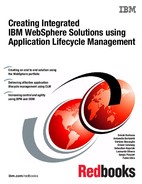
5. After execution of the test, browse through the recorded steps of the integration flow to inspect the input and output messages. Figure 5-6 shows the input message and the URL of the service that was invoked on the Integration Bus.
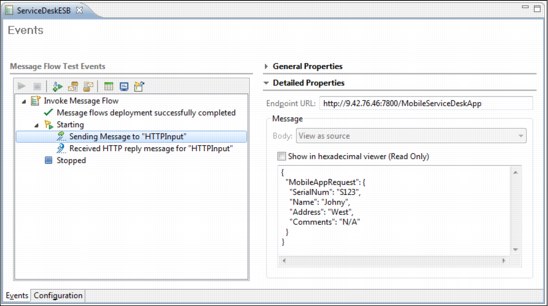
Figure 5-6 Performing unit testing with the Integration Bus: Simulating an incoming JSON message
6. Figure 5-7 shows the result generated by the Integration Bus that is normally sent to the client.
Optionally, you can save the test case as a file with an .mbtest extension in the integration application for later reuse.

Figure 5-7 Performing unit testing with the Integration Bus: A JSON result generated for the client
5.2 Create the web application for the scenario
In this section, we create a web application that performs one of the front-end access channels for our scenario. We use Eclipse integrated development environment (IDE) for Java Platform, Enterprise Edition (Java EE) developers to create the application. These tools make the development of applications for WebSphere Application Server faster and simpler, and include features, such as hot-deployment.
|
Note: If you are using the Rational Application Developer IDE family that supports your WebSphere Application Server:
•Skip section 5.2.1, “Install WebSphere Developer Tools in the Eclipse IDE” on page 123, which describes tools that are bundled with WebSphere Developer Tools and offer even more features. To learn more about the Rational development tools platform, see the following site:
•Proceed to 5.2.2, “Develop the web application” on page 123.
|
5.2.1 Install WebSphere Developer Tools in the Eclipse IDE
The easiest way to install the WebSphere Development Tools for your Eclipse IDE is to follow this procedure:
1. Open your Eclipse IDE and click Help → Eclipse Marketplace.
2. Search for the term WebSphere and click Go.
In the search result list, there are several versions of the IBM WebSphere Application Server Developer Tool plug-in that support different versions of WebSphere Application Server, including Liberty profile.
3. Select the version of the plug-in in your environment.
4. Click Install.
You can install more than one plug-in to support multiple versions of the WebSphere Application Server runtime environment.
5. With the installation or installations complete, restart the Eclipse IDE.
You can also download this plug-in, access documentation, and locate other resources on the WASdev web page. This page also contains information about Eclipse and WebSphere Development Tools compatibility:
5.2.2 Develop the web application
Follow this section to build and prepare your web application for our scenario.
Create the Java EE project
To create a dynamic web project follow these steps:
1. In the Eclipse IDE, select File → New → Dynamic Web Project.
2. Define the project:
a. Enter the name for your project, for example, ServiceDeskWebApp.
b. Select the runtime for your server, for example the Liberty profile.
c. Ensure that the Add project to an EAR check box is cleared.
These selections are shown in Figure 5-8.
3. In the same window, click Finish and the project will be generated.

Figure 5-8 Creating the web application project
|
Note: To keep track of the source code and enforce a common development policy, you can use IBM Rational Collaborative Lifecycle Management Solution tools. Appendix A, “Integrating the Eclipse environment with IBM Rational Collaborative Lifecycle Management” on page 223, shows the procedure for sharing this piece of solution in a Collaborative Lifecycle Management environment.
|
Create the application logic
With the dynamic web project created, create the controller with the application logic. For our scenario, this role is filled by a servlet with a helper class. Follow this procedure to create both of these artifacts:
1. In the Eclipse Enterprise Explorer project view, right-click the newly created project and select New → Servlet.
2. In the wizard window, in the Java package field, enter com.ibm.redbooks.supportDesk.servlets.
3. In the Class name field, enter ClaimServlet and click Finish.
4. In the newly created ClaimServlet class, replace the code with that in Example 5-8 and save your changes.
Example 5-8 ClaimServlet source code
package com.ibm.redbooks.supportDesk.servlets;
import java.io.IOException;
import java.io.PrintWriter;
import javax.annotation.Resource;
import javax.jms.Connection;
import javax.jms.ConnectionFactory;
import javax.jms.DeliveryMode;
import javax.jms.Destination;
import javax.jms.JMSException;
import javax.jms.MessageProducer;
import javax.jms.Session;
import javax.jms.TextMessage;
import javax.servlet.ServletException;
import javax.servlet.annotation.WebServlet;
import javax.servlet.http.HttpServlet;
import javax.servlet.http.HttpServletRequest;
import javax.servlet.http.HttpServletResponse;
import com.ibm.redbooks.supportDesk.helpers.ClaimHelper;
/**
* Servlet implementation class ClaimServlet
*/
@WebServlet("/ClaimServlet")
public class ClaimServlet extends HttpServlet {
private static final long serialVersionUID = -8909793799230592821L;
private static final String NAME_PARAM = "name";
private static final String ADDRESS_PARAM = "address";
private static final String SERIAL_NUMBER_PARAM = "serialNumber";
private static final String COMMENTS_PARAM = "comments";
@Resource(name = "jms/queueCF")
private ConnectionFactory qcf;
@Resource(name = "jms/inputQueue")
private Destination inputQueue;
public ClaimServlet() {
}
protected void doPost(HttpServletRequest request, HttpServletResponse response) throws ServletException, IOException {
doGet(request, response);
}
protected void doGet(HttpServletRequest request, HttpServletResponse response) throws ServletException, IOException {
System.out.println("ClaimServlet invoked!");
PrintWriter out = response.getWriter();
out.println("<html><head><title>Acknowledgement Of Claim Form</title></head><body>");
String name = request.getParameter(NAME_PARAM);
String address = request.getParameter(ADDRESS_PARAM);
String serialNumber = request.getParameter(SERIAL_NUMBER_PARAM);
String comments = request.getParameter(COMMENTS_PARAM);
out.println("<h2>Sending claim request for item with serial number: " + serialNumber + " </h2>");
String trackingNum = ClaimHelper.generateWebTrackingNumber();
String message = ClaimHelper.generateXML(serialNumber, name, address, comments, trackingNum);
System.out.println("Message:
" + message);
if (putMsgOnQueue(message))
out.println("<h2>Your request have been successfully sent to the Redbooks Support Desk! Your tracking number is " + trackingNum + "</h2>");
else
out.println("<h2>Your request was not successfully sent, please contact with the administrator</h2>");
out.println("<h3><a href="/ServiceDeskWebApp">Click</a> to return to the claim form</h3></body></html>");
}
/**
* Puts the message on the MQ queue using JMS
*
* @param message
* - XML message to be sent to the queue
* @return true if the sent was succesful
*/
private boolean putMsgOnQueue(String message) {
boolean sent = false;
Connection con = null;
MessageProducer sender = null;
try {
con = qcf.createConnection();
Session session = con.createSession(false, Session.AUTO_ACKNOWLEDGE);
sender = session.createProducer(inputQueue);
TextMessage textMessage = session.createTextMessage();
textMessage.setText(message);
sender.send(textMessage, DeliveryMode.PERSISTENT, 1, 0);
sent = true;
System.out.println("Message sent with ID: " + textMessage.getJMSMessageID().trim());
} catch (Exception e) {
e.printStackTrace();
} finally {
try {
sender.close();
} catch (JMSException e) {
e.printStackTrace();
}
try {
con.close();
} catch (JMSException e) {
e.printStackTrace();
}
}
return sent;
}
}
With the servlet ready, create the helper class:
1. In the Eclipse Enterprise Explorer project view, right-click the project and select New → Class.
2. In the wizard window, in Java package field, enter:
com.ibm.redbooks.supportDesk.helpers
3. In the Class name field, enter ClaimHelper and click Finish.
4. In the newly created ClaimHelper class, replace the code with that in Example 5-9 and save your changes.
Example 5-9 ClaimHelper source code
package com.ibm.redbooks.supportDesk.helpers;
import java.io.StringWriter;
import javax.xml.parsers.DocumentBuilder;
import javax.xml.parsers.DocumentBuilderFactory;
import javax.xml.parsers.ParserConfigurationException;
import javax.xml.transform.Transformer;
import javax.xml.transform.TransformerException;
import javax.xml.transform.TransformerFactory;
import javax.xml.transform.dom.DOMSource;
import javax.xml.transform.stream.StreamResult;
import org.w3c.dom.Attr;
import org.w3c.dom.Document;
import org.w3c.dom.Element;
public class ClaimHelper {
private static final String WEB_PREFIX = "WEB";
public static String generateXML(String serialNumber, String name,
String address, String comments, String trackingNum) {
String xml = null;
StringWriter writer = null;
try {
DocumentBuilderFactory docFactory = DocumentBuilderFactory
.newInstance();
DocumentBuilder docBuilder = docFactory.newDocumentBuilder();
// root elements
Document doc = docBuilder.newDocument();
doc.setXmlStandalone(true);
Element rootElement = doc.createElement("WebAppRequest");
Attr attr1 = doc.createAttribute("xmlns:xsi");
attr1.setValue("http://www.w3.org/2001/XMLSchema-instance");
Attr attr2 = doc.createAttribute("xsi:noNamespaceSchemaLocation");
attr2.setValue("webAppRequest.xsd");
rootElement.setAttributeNode(attr1);
rootElement.setAttributeNode(attr2);
doc.appendChild(rootElement);
Element serialNum = doc.createElement("SerialNum");
serialNum.appendChild(doc.createTextNode(serialNumber));
rootElement.appendChild(serialNum);
Element nameEl = doc.createElement("Name");
nameEl.appendChild(doc.createTextNode(name));
rootElement.appendChild(nameEl);
Element trackingEl = doc.createElement("TrackingNum");
trackingEl.appendChild(doc.createTextNode(trackingNum));
rootElement.appendChild(trackingEl);
Element addressEl = doc.createElement("Address");
addressEl.appendChild(doc.createTextNode(address));
rootElement.appendChild(addressEl);
Element commentsEl = doc.createElement("Comments");
commentsEl.appendChild(doc.createTextNode(comments));
rootElement.appendChild(commentsEl);
DOMSource domSource = new DOMSource(doc);
writer = new StringWriter();
StreamResult result = new StreamResult(writer);
TransformerFactory transformerFactory = TransformerFactory
.newInstance();
Transformer transformer = transformerFactory.newTransformer();
transformer.transform(domSource, result);
xml = writer.toString();
} catch (ParserConfigurationException pce) {
pce.printStackTrace();
} catch (TransformerException tfe) {
tfe.printStackTrace();
}
return xml;
}
public static String generateWebTrackingNumber() {
return WEB_PREFIX
+ Long.toHexString(Double.doubleToLongBits(Math.random()))
.toUpperCase().subSequence(0, 7);
}
}
The code for the servlet in Example 5-8 on page 125 does the following:
•Generates a unique tracking number using the ClaimHelper class.
•Generates an XML message that contains the user input and the tracking number.
•Sends a message to the WebSphere MQ queue manager using the putMsgOnQueue method.
•Generates HTML output for the user.
The important parts of code are:
@WebServlet("/ClaimServlet") Annotation that configures the servlet mapping URL.
@Resource(name = "jms/queueCF") This annotation is a reference that is used to obtain the connection to the WebSphere MQ queue manager.
@Resource(name = "jms/inputQueue") This annotation is a reference that is used to define the destination queue.
The code of the helper class shown in Example 5-9 on page 127 implements two static methods:
generateWebTrackingNumber() This is used to generate a random string that represents the tracking number.
generateXML() This uses a DOM parser to generate an XML message.
Create a claim form
To create the front-end page with a claim form, follow these steps:
1. Right-click the project and select New → JSP File.
2. In the wizard window, in the File Name field, enter index.jsp and click Finish.
3. In the newly created JavaServer Pages (JSP) file, replace the code with that in Example 5-10 and save your changes.
Example 5-10 Claim form source code
<%@ page language="java" contentType="text/html; charset=ISO-8859-1"
pageEncoding="ISO-8859-1"%>
<!DOCTYPE html PUBLIC "-//W3C//DTD HTML 4.01 Transitional//EN" "http://www.w3.org/TR/html4/loose.dtd">
<html>
<head>
<meta http-equiv="Content-Type" content="text/html; charset=ISO-8859-1">
<title>Redbooks Support Desk System</title>
</head>
<body>
<h2>Claiming Form</h2>
<form method="POST" action="/ServiceDeskWebApp/ClaimServlet">
<table>
<tbody>
<tr>
<td>Name:</td>
<td><input type="text" name="name" size="20"></td>
</tr>
<tr>
<td>Address:</td>
<td><input type="text" name="address" size="30"></td>
</tr>
<tr>
<td>Serial Number Of The Item:</td>
<td><input type="text" name="serialNumber" size="20"></td>
</tr>
<tr>
<td>Additional comments:</td>
<td><textarea name="comments" cols="20" rows="8"></textarea></td>
</tr>
<tr>
<td></td>
<td><input type="submit" value="Submit" name="SUBMIT"></td>
</tr>
</tbody>
</table>
</form>
<h6>Powered by IBM Redbooks Team</h6>
</body>
</html>
The role of the form presented in Example 5-10 is simple. It gathers the information from the user and sends an HTTP POST request to ClaimServlet.
|
Note: Neither the servlet or the JSP implement any security or validation functionality.
|
Browse through application resources
Figure 5-9 on page 131 shows the view of the created application in the Eclipse Java EE perspective.

Figure 5-9 Web application Java EE projects view
The most important elements of the application are highlighted in Figure 5-9 and defined as follows:
1. The main project packaging of all application code and resources.
2. Resource references used by the application for the connection factory and the queue.
3. Servlet mapping used to invoke the application controller logic.
4. The source code of the servlet and a helper class with static methods.
5. Libraries and runtimes used by the application in the Eclipse workspace.
6. The main JSP page with the claim form.
Figure 5-10 on page 132 presents the generated HTML output from the application in the browser.

Figure 5-10 Claim form presented by the web application
5.2.3 Export the application archive
To export the application for deployment, follow these steps:
1. Right-click the project and select Export → WAR.
2. In the wizard, click Browse and select the output location.
3. Ensure that the Optimize for a specific server runtime check box is cleared and click Finish.
The Application is saved to your chosen location in Java .war format.
5.3 Prepare the Liberty profile environment for your web application
The WebSphere Liberty profile was introduced with WebSphere Application Server version 8.5 and provides dynamic and simplified stand-alone runtime for web applications. It supports a subset of the programming model and runtime features that are available with WebSphere Application Server full profile. Any application that runs on the Liberty profile will also run on the full profile.
|
Note: For more information about the Liberty profile features and capabilities, refer to: WebSphere Application Server V8.5 Administration and Configuration Guide for Liberty Profile, SG24-8170.
|
To prepare your Liberty profile environment, follow these steps:
1. Configure the Java Runtime environment.
2. Install the Liberty profile runtime environment.
3. Create the server, and (optionally) configure features and add-ons for your application.
Obtain the latest Liberty profile package from the WASdev website:
5.3.1 Configure the Java runtime environment
The Liberty profile is not bundled with a Java Runtime Environment, but it needs one to run. It searches for the java command in the following order of properties: JAVA_HOME, JRE_HOME, and PATH.
Example 5-11 shows the commands for setting these properties on a Linux system.
Example 5-11 Setting the Java runtime environment on Linux
export JAVA_HOME=/opt/IBM/Java6
export PATH=$JAVA_HOME/bin:$PATH
|
Important: On distributed platforms, the minimum supported level for the IBM Java Development Kit (JDK) is 6.0 (J9 2.6) SR1 and Java 6 update 26 for Oracle.
|
5.3.2 Installation
To install the Liberty profile environment in text mode, follow these steps. The Liberty profile environment is one of the fastest ways to start working with the server:
1. Run the command to extract the contents of the Liberty archive, for example:
java -jar wlp-developers-runtime-8.5.5.3.jar
2. Accept the license agreement.
3. Press 1 to agree to the license terms and proceed.
4. Provide the installation path for the Liberty profile, for example /opt/IBM/WebSphere, and press Enter.
|
Note: The Liberty profile can be also installed using the IBM Installation Manager in either graphical and text mode. For more information, see the following site:
|
5.3.3 Create and configure the server
To create a new Liberty profile server, run the server command from the bin directory of the Liberty profile runtime environment. For example, on a Linux or UNIX system, run following command:
./server.sh create server1
This command creates the server1 instance in the /usr/servers subdirectory, along with the server.xml configuration file, which we will use to configure the Liberty profile server.
For our scenario, the web application requires that the runtime server provide additional Java Message Service (JMS) and Java Naming and Directory Interface (JNDI) resources on the server. This is because the application connects to WebSphere MQ. The Liberty profile server also has to be configured to use an external JMS messaging provider. For that purpose, we use the WebSphere MQ resource adapter. You can read about this adapter and download it from following web page:
After downloading and extracting the WebSphere MQ resource adapter, you need to refer to its installation path in the Liberty profile configuration file, using variable property named wmqJmsClient.rar.location:
<variable name="wmqJmsClient.rar.location" value="YOUR_PATH/wmq.jmsra.rar" />
Example 5-12 shows a completed configuration file for the Liberty profile server to run the application for the scenario.
Example 5-12 Complete Liberty profile configuration to run the application
<server description="new server">
<!-- Enable features -->
<featureManager>
<feature>jsp-2.2</feature>
<feature>wmqJmsClient-1.1</feature>
<feature>jndi-1.0</feature>
</featureManager>
<httpEndpoint id="defaultHttpEndpoint"
host="*"
httpPort="9080"
httpsPort="9443" />
<variable name="wmqJmsClient.rar.location" value="/opt/ibm/liberty/wmqadapter/wmq/wmq.jmsra.rar" />
<connectionManager id="ConMgr" maxPoolSize="2" />
<jmsConnectionFactory jndiName="jms/queueCF" connectionManagerRef="ConMgr">
<properties.wmqJms
transportType="CLIENT"
hostName="iib.raleigh.ibm.com"
port="1414"
channel="WAS.CONN"
queueManager="IB9QMGR" />
</jmsConnectionFactory>
<jmsQueue id="jms/inputQueue" jndiName="jms/inputQueue">
<properties.wmqJms
baseQueueName="WEB_IN"
baseQueueManagerName="IB9QMGR" />
</jmsQueue>
</server>
As you can see from Example 5-12 on page 134, the Liberty profile uses the jsp-2.2 feature to run the servlet that processes the XML message. The Jndi-1.0 and wmqJmsClient-1.1 features are used for messaging and connectivity with the WebSphere MQ. The jmsConnectionFactory and jmsQueue properties are set to point to the correct resources and destination on the WebSphere MQ queue manager.
5.3.4 Deploy the application manually
To deploy manually, start the server and deploy the application as follows. Use the following command to start the Liberty profile server1 runtime environment:
server start server1
To install the application, use the archive that was generated in 5.2.3, “Export the application archive” on page 132.
Copy the archive to the dropins folder, located in the server1 directory structure. Alternatively, add the following property to the server.xml configuration file, indicating the location of your application:
<webApplication id="ServiceDeskWebApp" location="${server.config.dir}/apps/ServiceDeskWebApp.war" name="ServiceDeskWebApp"/>
|
Note: This chapter covers only the basic Liberty profile configuration capabilities. To learn more about using the Liberty profile, see:
WebSphere Application Server V8.5 Administration and Configuration Guide for Liberty Profile, SG24-8170.
Also see the IBM Knowledge Center at the following location:
|
Now you can run the application and see the user claim form shown in Figure 5-10 on page 132. Enter the following URL in a browser (port 9080 is a default HTTP inbound port for Liberty profile, but it can be dynamically changed by updating the httpEndpoint property in the server.xml configuration file):
5.4 Prepare WebSphere Application Server full profile environment for web application
To prepare the WebSphere Application Server full profile environment for the web application prepared in 5.2, “Create the web application for the scenario” on page 123, follow this procedure:
1. Install the WebSphere Application Server runtime environment.
2. Create a profile.
3. Start and configure the server.
4. Deploy the application.
5.4.1 Install and create the server profile
The WebSphere Application Server can be installed in various configurations, including Base (stand-alone) and network deployment topologies. For our scenario, we use a stand-alone configuration of WebSphere Application Server profile, version 8.5.5.1.
Detailed process steps for installing the WebSphere Application Server and for creating an application server profile are included in WebSphere Application Server V8.5 Administration and Configuration Guide for the Full Profile, SG24-8056.
5.4.2 Configure the server
With your WebSphere Application Server installed and stand-alone profile ready, start the server by running the following command from the installed profile bin directory:
./serverStart.sh server1
To display the administrative console, go to the following URL (port 9060 is a default administrative port, but it can be changed during or after profile creation):
http://<hostname>:9060/ibm/console
|
Note: If you installed a WebSphere Network Deployment Cell environment, connect to the deployment manager server host to access the console.
If you did not enable security during profile creation, click Log in on the Welcome page without providing any credentials. If security is enabled, enter the administrative user name and password, then click Log in.
|
To prepare the environment for the application that was prepared in 5.2, “Create the web application for the scenario” on page 123, create and configure the messaging providers and destination queue in the server runtime environment:
1. In the administrative console, click Resources → JMS → Connection factories.
2. Select the scope for the connection factory. If you are using network deployment topology to access resources, this setting provides access to other servers. For this scenario, select the cell scope and click New.
3. Select WebSphere MQ messaging provider and click OK.
4. Enter queueCF in the Name field, jms/queueCF in the JNDI name field, and click Next.
5. Use the default option to Enter all required information into this wizard and click Next.
6. Enter the name of your queue manager in the Queue manager or queue sharing group name field. In our scenario, we use IB9QMGR for the queue manager name.
7. Click Next.
8. Select Client from the Transport drop-down menu, then supply the Hostname, Port, and Server connection channel with the parameters of your queue manager. An example is shown in Figure 5-11.

Figure 5-11 Configuring the connection factory for the WebSphere MQ messaging provider
9. Click Next.
10. Click Test connection. If the test is successful, click Next.
11. In the summary window, confirm that the parameters you provided match those of your WebSphere MQ queue manager.
12. Click Finish.
With the connection factory defined, create the destination definition:
1. In the administrative console, click Resources → JMS → Queues.
2. Select the same scope that you chose for the connection factory in Step 2 on page 136, and click New.
3. Select WebSphere MQ messaging provider and click OK.
4. Enter inputQueue in the Name field, jms/inputQueue in the JNDI name field, WEB_IN in the Queue name field, and click OK.
To commit your changes to the WebSphere Application Server runtime environment, click Save in the message box that displays in the top of the window, as shown in Figure 5-12 on page 138.
Figure 5-12 Saving any configuration change on WebSphere Application Server full profile
This is especially important when working with network deployment environments because changes made in the deployment manager have to be synchronized across the whole cell where multiple servers can be defined.
|
Tip: You can manually enforce synchronization by clicking System administration → Nodes, then selecting the nodes and clicking the Synchronize button.
|
5.4.3 Deploy the application manually
With the configuration created (see 5.4.2, “Configure the server” on page 136), the WebSphere Application Server runtime environment is ready to host the application for our scenario. Follow these steps to deploy the application that was created in 5.2.3, “Export the application archive” on page 132:
1. In the administrative console, click Applications → New Application.
2. Click New Enterprise Application.
3. Click Browse and locate the WAR file for the application (ServiceDeskWebApp.war) and click Next.
4. Select the Fast Path option and click Next.
5. In the Install New Application wizard, map the JNDI resources to application references. Use the Browse button to look up the resources you defined in “Create the application logic” on page 124, or type their names manually. In the application in our scenario, we used the same names for references and resources.
6. Click the Summary step link (or click Next until you reach the last step of the wizard), and click Finish.
7. Wait for changes to synchronize on the WebSphere Application Server, and click Save to commit the changes to the runtime environment.
The default behavior of the WebSphere Application Server full profile is that a new application is in stop state after installation. To start it, follow these steps:
1. In the administrative console, click Applications → Application Types → WebSphere enterprise applications.
2. Select the ServiceDeskWebApp application and click Start.
|
Tip: After deploying the application, you can still access and modify the resource references. To do so, click your application, and select the Resource references link in the References section.
|
Now you can run the application and see the user claim form shown in Figure 5-10 on page 132. Enter the following URL in the browser (port 9080 is a default HTTP inbound port for the WebSphere Application Server full profile, but it can be changed during and after profile creation):
Figure 5-10 on page 132 shows the application form that should be displayed.
5.5 Create the mobile application for our scenario
This section describes the development of the mobile application using Worklight Studio.
In our scenario, the mobile application implements a basic functionality by enabling the user to create a claim and retrieve a tracking number.
To communicate with the back-end system, the application uses a Worklight HTTP adapter, which calls a Representational State Transfer (REST) service implemented in the Integration Bus.
Worklight Studio enables the creation of mobile applications for multiple platforms, such as Android, iOS, and Windows phones, among others. For a complete list of supported platforms and corresponding system requirements, see the following site:
In our scenario, we use Worklight Studio to create both a mobile website and an Android application.
5.5.1 Prepare the development environment
For developing the mobile application for our scenario, we need to install Worklight Studio and the Android software development kit (SDK).
Install Worklight Studio
Worklight Studio is an Eclipse installation, which is enhanced with specific plug-ins.
At the time of this writing, the supported versions of Eclipse are Juno SR2 (4.2.2), Kepler SR1 (4.3.1), and Luna (4.4). Any other version of Eclipse is not officially supported and can present unsolved dependencies that might compromise the development process.
For our scenario, we use Eclipse Juno SR2 (4.2.2) for easy integration with Rational Team Concert plug-ins.
If you are planning to use Rational Team Concert, refer to the plug-in installation at “Install the Rational Team Concert Eclipse plug-in” on page 225. Also, an additional process is required to enable the plug-in coexistence. Refer to the product documentation at the following link:
To install Worklight Studio, follow these steps:
1. Download Eclipse Juno SR2 (4.2.2) from the Eclipse Foundation site, choosing the Eclipse IDE for Java EE Developers version:
2. Extract the downloaded file.
3. Open Eclipse by clicking the executable file in the installation folder.
4. Choose the workspace folder. You can leave the default location as-is, or change it.
5. From the Eclipse menu, select Help → Eclipse Marketplace.
6. In the Find box, enter Worklight and click Go.
7. In the search results, select IBM Worklight Studio.
8. Click Install.
Install the Android SDK
The Android SDK is needed to generate Android applications. Download it at:
At the time of writing this book, three installation options are available:
•Download Eclipse ADT: This option downloads the full development environment, including a customized version of Eclipse, the Android SD, and tools.
•Download Android Studio: An integrated development environment, currently in Beta.
•Download the stand-alone Android SDK Tools: This downloads the SDK for an existing IDE. This is the preferred choice for adding Android application development capabilities to an existing Worklight Studio installation.
After installing the Android SDK, at least one Android platform environment needs to be downloaded. This is achieved by using the Android Manager and selecting the platform version to download. In our scenario, we used platform version 19, but other versions can be selected for developing applications for specific platform versions.
Install the Android development tool (ADT) plug-in for Eclipse
To install the ADT plug-in for Eclipse, follow these steps:
1. From the Eclipse menu, select Help → Eclipse Marketplace.
2. In the Find text box, enter ADT and click Go.
3. Select Android Development Tools for Eclipse and click Install.
4. Restart the Eclipse IDE after the installation is complete.
5.5.2 Develop the mobile application
Developing the mobile application consists of the following steps:
Create the application
To create the UI for the application, follow these steps:
1. Open Worklight Studio.
2. When prompted, enter a folder name to be used as the workspace location.
3. Before starting the development process, it is recommended to switch to the Design perspective. Even if it is not strictly necessary to use this perspective, it will ease the Worklight development process.
To change to the Design perspective, select Window → Open Perspective → Other and select Design from the list.
4. To create a new project, select File → New → Worklight Application Project. You can start defining the Worklight project properties as shown in Figure 5-13.

Figure 5-13 Defining properties for a new Worklight project
5. Enter a name for the project, select the Hybrid Application type, and click Next.
When choosing the project name, keep in mind that a single project can contain many applications. For our scenario, we named the project ServiceDeskProject.
6. Enter the application name, as shown in Figure 5-14 on page 142.

Figure 5-14 Defining the applications for a new project
7. Configure the necessary JavaScript libraries by clicking Configure JavaScript Libraries, as shown in Figure 5-15 on page 143.

Figure 5-15 Configuring JavaScript Libraries
8. For our application, we used jQuery Mobile as the JavaScript framework. Check the Add jQuery Mobile option to enable the additional configuration.
9. To use jQuery Mobile in the application, point to a local copy of the framework. To do that:
a. Download a stable version of the framework from http://jquerymobile.com.
b. Save the framework as a compressed file in a local folder. For our scenario, and at the time of this writing, we downloaded version 1.4.3, which was marked as the latest stable version.
10. In the Location text box, enter or browse for the path to the downloaded compressed file.
11. The files that are contained in the compressed file are available for selection. For our sample application, it is enough to select the images folder and the main .js and .css files for the corresponding jQuery Mobile version. So, for our scenario, we selected jquery.mobile-1.4.3.css and jquery.mobile-1.4.3.js.
|
Note: Remember that the file names might change with different releases of the framework. If the required files are not included, some jQuery Mobile features might not work properly in the application.
|
12. Click Finish to close the JavaScript configuration windows.
13. Click Finish in the application creation window. After some processing, the default content for the project and application is created, as shown in Figure 5-16.

Figure 5-16 Default workspace view for a new project
|
Note: To keep track of the source code and enforce a common development policy, you can use IBM Rational Collaborative Lifecycle Management Solution tools. Appendix A, “Integrating the Eclipse environment with IBM Rational Collaborative Lifecycle Management” on page 223, shows the procedure for sharing this project in a Collaborative Lifecycle Management environment.
|
Create the UI
To create the UI, we use the main application HTML file (index.html) and create two content sections: one for sending claim information and one for displaying the associated tracking number. Each section displays dynamically, depending on the application logic.
Set up the claim form and tracking number windows
To set up and define the claim form and tracking number windows, follow these steps:
1. Edit the index.html file located in the ServiceDeskProjectappsClaimAppcommon folder.

Figure 5-17 Editing the index.html file
3. To create the claim form and tracking number windows, start by duplicating the division (div) marked data-role=”page” and editing the corresponding id value of each division.
4. Name the first div, id=”claim_form_page” and the second div, id=”tracking_number_page”. The Hello Worklight content can be deleted. Figure 5-18 on page 146 shows the edited text.
|
Note: The Mobile Navigation panel in the lower left of the window can be used for easy navigation among pages.
|
Figure 5-18 Adding pages to index.html
Define the Claim Form window
Continue by defining the claim form window:
1. To create the content for the claim form, select the current content in the Mobile Navigation view. Click the Design tab in the source code section of the window.
2. Locate the jQueryMobile Widgets section in the Palette view, and scroll to the Header component.
3. Drag the Header component into the Design view, in the claim_form_page div.
4. Replace the default header text with Claims.
5. Create the fields to complete the claim form. Begin by inserting a Form in which to group all of the input fields. This is only used by the Reset button, usually there is no need to insert a form to process the fields, given that we will be accessing these values using jQuery.
6. Locate the Form widget in the jQueryMobile Widgets section, and drag it underneath the header section. Change the id value to a unique object id, such as claimForm, as shown in Example 5-13.
Example 5-13 Form definition
<form id="claimForm" action="">
7. Locate the Text widget in the jQueryMobile Widgets section, and drag it into the claim_form_page div in the form section. If you look into the source section, you will see that two components have been added: one label tag and one input tag. After editing, these objects will be tied together. The value of the for attribute of the label will also be the id value of the input. The default drag and drop generates the code shown in Example 5-14 on page 147.
Example 5-14 Text input default definition
<label for="text">Text Input:</label><input type="text" name="text" id="text">
8. Edit the label code using the name value for the for attribute, and Name as label text.
9. Edit the input name and input id values using name for each of these values. The final code is shown in Example 5-15.
Example 5-15 Text input for Name field
<label for="name">Name:</label><input type="text" name="name" id="name">
10. Repeat the process to add two more text fields and a text area: address, serial, and comments, respectively. You can also copy and paste the previous line three times to define these remaining input fields. The last field (comments) is a text area, rather than a simple text field, so the syntax is different. The completed, edited fields are shown in Example 5-16.
Example 5-16 Modified text inputs
<label for="name">Name:</label><input type="text" name="name" id="name">
<label for="address">Address:</label><input type="text" name="address" id="address">
<label for="serial">Serial #:</label><input type="text" name="serial" id="serial">
<label for="comments">Comments:</label><textarea id="comments"></textarea>
11. Finally, add two buttons: one for submitting the form and one for clearing form contents. To begin, drag a Button widget, and place it below the text area. Edit the Button href, text, and button id values.
12. Add an onClick event definition to call the JavaScript that calls the HTTP adapter. This will send the form data to the back end. In section “Code the JavaScript implementation” on page 154, we define the JavaScript function named submitClaimForm, which receives the obtained values from the window, as parameters, as shown in Example 5-17.
Example 5-17 Submit button
<a href="#tracking_number_page" data-role="button" id="submit"
onClick='submitClaimForm(claimForm.serial.value, claimForm.name.value, claimForm.address.value, claimForm.address.value);' data-inline="true">Submit</a>
13. Drag and drop another button and edit the code, adding the data shown in Example 5-18.
Example 5-18 Reset button
<a href="#" data-role="button" id="button0" data-inline="true" onClick='claimForm.reset();'>Reset</a>
14. Add a data-inline=”true” attribute for both buttons. This is for cosmetic reasons only.
15. The input form in the UI is ready. Click Save.
Define the Tracking Number window
Continue by defining the Tracking Number window, which will show the tracking number retrieved from the back end:
1. In the Mobile Navigation panel, double-click the tracking_number_page option to display the current state of the page in the design panel.
2. Drag and drop a Header widget and use Tracking Info as header text.
3. Drag and drop a Label widget, and place it into the content area of the tracking_number_page below the header.
4. Edit the object using resultMessage as the id, and leave the text area of the label blank. This space will be used by the scripts to display the tracking number.
5. Drag and drop a Button widget, using the href value that references the claim form page, and Back as text. For our scenario, we also defined the button as inline and used the back icon. This section of code is shown in Example 5-19.
Example 5-19 Tracking number page content
<div data-role="page" id="tracking_number_page">
<div data-role="header" id="header0" data-position="fixed">
<h3>Tracking Info</h3>
</div>
<div data-role="content" style="padding: 15px">
<label id="resultMessage"></label>
<a href="#claim_form_page" data-role="button" id="button" data-icon="back"
data-inline="true" data-mini="true" onClick="showFormPage();">Back</a>
</div>
</div>
6. Click Save and close the page editor.
Create the HTTP adapter
The HTTP adapter is used to communicate the mobile application with the back-end server.
To create an HTTP adapter, follow these steps:
1. Select File → New → Worklight Adapter. Figure 5-19 on page 149 shows the adapter creation window.

Figure 5-19 New Worklight adapter
2. Populate the form using the following data:
– Project name: The name of the project, in our case ServiceDeskProject.
– Adapter type: The type of connection to establish, in our case HTTP Adapter.
– Adapter name: A unique name for the adapter, in our case, Backend.
3. Click Finish. A new folder named Backend is now created in the Adapters folder and contains the following files:
– Backend.xml: Contains the adapter configuration, such as destination IP, or port.
– Backend-impl.js: Contains the JavaScript that implements the adapter logic.
– filtered.xsl: Contains the data transformation definition. This file is not needed in our scenario, and can be deleted.
Figure 5-20 on page 150 shows the new adapter with its default values.

Figure 5-20 Default values for the new adapter
The new adapter is created with sample values, and these need to be modified. To change the adapter values, follow these steps:
1. Expand the Connectivity section to edit the Connection Policy values, as shown in Figure 5-21 on page 151.

Figure 5-21 Editing the adapter
2. Populate the Domain and Port values, using the address and port of the back-end server. These values are used by the adapter as the base URL for communicating with the back-end.
3. Delete the predefined procedures getStories and getStoriesFilter, shown in Figure 5-22 on page 152 by selecting each one and clicking Remove.

Figure 5-22 Deleting the getStories and getStoriesFilter default procedures
4. Add a new procedure by clicking the Add button, and naming it submitClaim, as shown in Figure 5-23 on page 153.

Figure 5-23 Defining adapter methods
5. Switch to the Source view of the adapter. The code displays as shown in Example 5-20.
Example 5-20 Backend adapter source view
<?xml version="1.0" encoding="UTF-8"?>
<!--
Licensed Materials - Property of IBM
5725-I43 (C) Copyright IBM Corp. 2011, 2013. All Rights Reserved.
US Government Users Restricted Rights - Use, duplication or
disclosure restricted by GSA ADP Schedule Contract with IBM Corp.
-->
<wl:adapter name="Backend"
xmlns:xsi="http://www.w3.org/2001/XMLSchema-instance"
xmlns:wl="http://www.worklight.com/integration"
xmlns:http="http://www.worklight.com/integration/http">
<displayName>Backend</displayName>
<description>Backend</description>
<connectivity>
<connectionPolicy xsi:type="http:HTTPConnectionPolicyType">
<protocol>http</protocol>
<domain>your_server_ip</domain>
<!-- Following properties used by adapter's key manager for choosing specific certificate from key store
<sslCertificateAlias></sslCertificateAlias>
<sslCertificatePassword></sslCertificatePassword>
-->
<port>your_server_port</port>
</connectionPolicy>
<loadConstraints maxConcurrentConnectionsPerNode="2" />
</connectivity>
<procedure name="submitClaim" />
</wl:adapter>
6. Click Save and close the adapter file.
Code the JavaScript implementation
With the adapter defined, we need to write the JavaScript code for the actual implementation:
1. Open the Backend-impl.js file for editing. The file contains commented code for reference.
2. Delete all non-commented code before writing the adapter code.
The code in Example 5-21 implements the call to the backend server.
Example 5-21 Server adapter call
function submitClaim(serial, name, address, comments) {
var input = {
method : 'post',
returnedContentType : 'json',
path : '/MobileServiceDeskApp',
body:{
contentType:'application/json; charset=UTF-8',
content:
JSON.stringify({
"MobileAppRequest": {
SerialNum": serial,
Name": name,
Address": address,
Comments": comments
}
})
}
};
return WL.Server.invokeHttp(input);
}
By using this code, we are invoking a REST service at: http://<your_server_ip>:<your_server_port>/MobileServiceDeskApp, using the HTTP POST method and encoding the received parameters in JSON format.
Deploy the adapter to the server and test the adapter
Deploy the adapter to the local server. Following that, we can save and test the adapter:
1. Go to the Project Explorer view, the adapters folder.
2. Right-click the adapter name, and select Run As → Deploy Worklight Adapter. The adapter is now deployed to the local server.
3. Test the adapter using sample data. To do so, select the adapter name in the adapters folder in the Project Explorer view.

Figure 5-24 Testing the adapter
5. Adapter invocation requires that four, comma-separated input parameters be executed. For testing purposes, any values can be provided. Click Run to execute the adapter.
If the adapter is well defined and the back-end server is running, you obtain a response similar to that in Figure 5-25.
Figure 5-25 Adapter invocation result
Call the adapter from the UI
The last step in mobile application development is to link the UI and the adapter, so that when the user clicks the Submit button, the adapter is called using the values captured on the input form.
During UI development, a JavaScript method named submitClaimForm() was invoked in the onClick event of the Submit button. This method is defined in the JavaScript portion of the project. Because it is the same for all environments, adding the corresponding code to the common components is enough.
1. Open the main.js file located in apps/ClaimApp/common/js. At this time, the file contains only the default initialization code of the wlCommonInit() function.
Example 5-22 Adapter invocation in main.js
function submitClaimForm(serial, name, address, comments) {
var invocationData = {
adapter : 'Backend', // adapter name
procedure : 'submitClaim', // procedure name
parameters : [serial, name, address, comments] // parameters if any
};
WL.Client.invokeProcedure(invocationData, {
onSuccess : dataSentOK,
onFailure : dataSentError
});
}
3. In this function, we are receiving the claim form input parameters and constructing the HTTP adapter call to invoke the adapter that was created in “Create the HTTP adapter” on page 148. Note that two additional functions are required, mapped as onSuccess and onFailure in the adapter call, and shown in Example 5-23.
Example 5-23 Adapter invocation post-processing
function dataSentOK(result) {
if ("OK"== result.invocationResult.MobileAppResponse.ResponseCode) {
$("#resultMessage").html("Your claim has been received.<br>Tracking #: "+result.invocationResult.MobileAppResponse.TrackingNumber);
}
else {
$("#resultMessage").html("Your claim has been rejected.<br>Please contact Customer Service.");
}
}
function dataSentError(result) {
$("#resultMessage").html("We are experiencing technical difficulties.<br>Please retry your operation later.");
}
4. In a normal execution of the adapter, a response code will be retrieved, along with the tracking number if the operation was successful. The corresponding messages will be displayed in the results window.
5. If there is an execution error (such as connectivity problems), a different message will be delivered to the user.
6. Save and close the file.
Deploy and test
Now, development is complete, and the full UI and adapter integration can be tested.
Assuming that the adapter is deployed and tested as indicated in section “Create the HTTP adapter” on page 148, we are ready to build the application environment for preview and unit testing.
Build the application environment
Build the application environment by following these steps:
1. Right-click apps/ClaimApp and select Run As → Build all Environments. This starts the build process.
2. Monitor the build process in the Console view. If there are no errors, the following message in Example 5-24 displays.
Example 5-24 The build process completes without errors
[yyyy-mm-dd hh:mm:ss] Application 'ClaimApp' with all environments build finished.
Test the application
Now, test the application by following these steps:
1. Right-click apps/ClaimApp and select Run As → Preview. The mobile browser simulator will be opened in your default browser, showing the application in a simulated mobile device.
Keep in mind that the mobile browser simulator uses a Java applet, so the default browser must have a configured Java Runtime Environment. Also, some security warnings might display the first time that the tool is executed. Just accept and allow the execution of the presented content. Otherwise, the mobile application might not work properly.
Figure 5-26 on page 158 shows the application running in the mobile browser simulator.

Figure 5-26 Mobile browser simulator
Generating the application for different platforms
One of the main capabilities of Worklight is the ability to generate multiple-platform applications. Specific requirements might be needed to generate a native application that can be installed on a real device. To check for these requirements, see the IBM Knowledge Center:
For our scenario, we generate both an Android application and a mobile website.
Generate an Android and a mobile web application
To create a new environment, follow these steps:
1. In Worklight Studio, select File → New → Worklight Environment.
2. Select the project and application and check the Android phones and tablets option and the Mobile web app option, as shown in Figure 5-27 on page 159.

Figure 5-27 New Worklight environment
3. Click Finish, and the two folders are created under ClaimApps: an android folder and a mobilewebapp folder.
4. Now, build the new environment. Right-click ClaimApps and select Run As → Build All Environments.
5. When the building process ends, a new Android project is created. It is named using the pattern <protect_name><app_name>Android. In our scenario, the name is ServiceDeskProjectClaimAppAndroid.
6. This is a normal Android project, so it can be tested as such. Right-click the ServiceDeskProjectClaimAppAndroid project and select Run As → Android Application. This launches the Android emulator and runs the application inside it.
5.5.3 Install the application on the server
To install the mobile application on the Worklight server for the first time, follow these steps:
Generate the installable assets
To deploy the application to an external Worklight server, a few configuration steps are needed.
The application is exported in the form of a .war file, which is generated by you, to the target Worklight server. After the export and installation of the .war file, the Worklight console is enabled and is used to install the remaining components: the Worklight application and the HTTP adapter.
1. To generate the .war file, in Worklight Studio, right-click the ClaimApp application and select Run As → Build Settings and Deploy Target. Figure 5-28 shows the configuration window for this file.
Figure 5-28 Configure your Worklight build and deploy the target
2. In the window that displays (Figure 5-28), check the first two check boxes if they are not selected. This optimizes the size of the deployed application.
3. Check the option to Build the applications to work with a different Worklight server. This updates the calls and references to the new server installation. Include the destination server name or IP address and a context path.
The context path is part of the invocation when accessing the application from the mobile-web environment. In our scenario, we chose /ServiceDesk.
4. Click Ok.
5. Build the application by right-clicking ClaimApp and selecting Run as → Build All Environments.
6. Look in the bin folder for the ServiceDeskProject and the newly generated files. Copy the following files, as they will be used later for installation:
– Backend.apapter: The adapter installer
– ClaimApp-all.wlapp: The application installer
– ServiceDeskProject.war: The war file containing the application runtime environment
Install the base software
There are several approaches to installing a mobile application on the Worklight server.
For our scenario, we chose to use the Server Configuration Tool for the initial application deployment. For a complete reference of installation choices, see the product documentation at the IBM Knowledge Center:
To do the installation using our selected method, follow these steps:
1. Install the supporting database. In our scenario, we chose an IBM DB2 compact installation, without modifying the default configuration values. Other database management systems are supported. For a list of these, see the product documentation at the IBM Knowledge Center:
2. Install the application server to run Worklight. In our scenario, we chose to use IBM WebSphere Application Server Liberty Core.
3. After installing the application server, but before starting the Worklight installation, it is necessary to create an empty server instance on the application server. Navigate into the bin folder of the Liberty installation, and execute the following command:
./server create myServer
4. Using the IBM Installation Manager, start the installation of the Worklight Server similarly as you did in the previous step. After selecting the location and features, a window provides configuration information, as shown in Figure 5-29.

Figure 5-29 IBM Worklight server configuration
5. For our scenario, we did not need to install the Worklight Application Center. Therefore, when prompted to install the Application Center, choose No and click Next.
6. No further configuration is needed, and so the next windows can be bypassed by clicking Next, according to the on-screen instructions. At the last window, the server installation starts.
7. At the end of the installation, click Finish.
You are ready to use the Worklight Server Configuration Tool.
Configure the server
To configure the server using the Server Configuration Tool, follow these steps. It is expected that the instance owner is performing these configuration steps:
1. Navigate to: <worklight_base_dir>/WorklightServer/ConfigurationTool/<your_platform> and locate the corresponding executable ServerConfigurationTool file.
2. Start the Server Configuration Tool by executing the file found in the previous step.
Figure 5-30 Server Configuration Tool
4. Enter a configuration name, such as base, and click OK. The Configuration Details window displays, as shown in Figure 5-31 on page 163.

Figure 5-31 The Configuration Details window
5. Leave the default values as they are, and click Next to advance to the Console Settings window, as shown in Figure 5-32 on page 164.

Figure 5-32 The Console Settings window
6. Leave the default values as they are, and click Next to advance to the Database choice window, as shown in Figure 5-33 on page 165.

Figure 5-33 Database choice window
7. In the Database choice window, select the supporting database installation, which, for our scenario, is IBM DB2. Click Next to advance to the DB2 Database Settings window, as shown in Figure 5-34 on page 166.
Figure 5-34 The DB2 Database Settings window
8. In the DB2 Database Settings window, enter the database server location, port, and driver. For our scenario, we used:
– Default port: localhost, 5000: Modify this for your system.
– Driver location: /opt/SA-W401/ibm/db2/V10.5/java/db2jcc4.jar: The link for downloading the DB2 driver is in the bottom of the window. (This link is not visible in Figure 5-34.)
9. Click Next to advance to the DB2 Database Additional Settings window, as shown in Figure 5-35 on page 167.

Figure 5-35 DB2 Database Additional Settings window
10. In the DB2 Database Additional Settings window, we chose the simple mode, as this allows the tool to create the databases automatically.
11. For the user and password credentials, we entered db2inst1, which refers to the DB2 instance owner in our system. You can also use any user with the privilege to create databases in your system. Click Next to advance to the Create DB2 Databases window, as shown in Figure 5-36 on page 168.
|
Note: If for any reason the tool is unable to create the database in simple mode, you can switch to advanced mode and create the WRKLGHT database from outside the tool. In the next step, it will be recognized as an existing database and the process will continue.
|

Figure 5-36 The Create DB2 Databases window
12. The next window confirms that the user has permission to create the database. Because we are using the instance owner, this is usually not a problem. Click Next to advance to the Application Server Selection window, as shown in Figure 5-37.
Figure 5-37 Application Server selection
13. In the Application Server Selection window, choose the application server that was installed to support IBM Worklight. For our scenario, we used the WebSphere Application Server. Click Next to advance to the Application Server Settings window, as shown in Figure 5-38.
Figure 5-38 The Application Server Settings window
14. In the Application Server Settings window, choose the installation path for the application server. For our scenario, we used /opt/SA-W401/IBM/WebSphere/Liberty. If the path is correct, the profile and server that were created in Step 3 on page 161 will be available for selection.
15. Ensure that the Create default user option remains checked. This user will be able to access the Worklight console and can change this setting if needed. For simplicity, we retained the default value.
16. Click Save to save all of the changes. Then, click Deploy to begin the server deployment.
17. Check the console as the operation progresses.
Create a Worklight runtime environment
The next step is to create a Worklight environment and import the server component of the mobile application:
1. In the ServerConfigurationTool main window select the option to Add a Worklight Runtime Environment to a Configuration.
2. When prompted, select a configuration and a name for the environment. For our scenario, there is only one configuration named base. For the environment name, we chose base Environment.
Figure 5-39 The Runtime Configuration Description window
4. Import the project .war file that was generated in “Generate the installable assets” on page 160. Click the Browse button and select the file.
5. For Worklight application context root, use /worklight value, and click Next to advance to the DB2 Database Additional Settings window, as shown in Figure 5-40 on page 171.

Figure 5-40 The DB2 Database Additional Settings window
6. Select Simple mode: Use default database names, and enter the user name and password for database access. For our scenario, we chose db2inst1 for both of these values. Click Next to advance to the Create DB2 Databases window, as shown in Figure 5-41.

Figure 5-41 The Create DB2 Databases window
7. We are using the database that was created in Step 10 on page 167, and so no additional configuration is needed. Click Save. Then, click Deploy to deploy the environment.
8. Monitor the console messages to verify the deployment. If there are no errors, close the Server Configuration Tool.
Add the mobile application
Using the Worklight console, add the mobile application to the server and enable it to be used by remote clients.
To add the application to the server, follow these steps:
1. Start the server that was created in Step 3 on page 161 by executing the following command at the bin folder of WebSphere Application Server Liberty Core installation:
./server start myServer
2. Open a web browser to access the Worklight console at http://<server_ip>:<server_port>/worklightconsole, using your server IP and application server port. For our scenario, we use port 9080 as it is the default WebSphere Liberty port.
3. When prompted, enter the user name and password that were defined in step 14 on page 169. For our scenario, we left the default user name and password as demo. Figure 5-42 shows the console login. Click Log in to advance into the console workspace.

Figure 5-42 The Worklight Console login window
4. An empty workspace displays, as shown in Figure 5-43 on page 173. We need to import the remaining application files that were created in “Generate the installable assets” on page 160.

Figure 5-43 Installing application using the Worklight Console
•Click the Browse button and select the application file named ClaimApp-all.wlapp saved in step 6 on page 160 from the file system and click Submit. The application will be installed as shown in Figure 5-44.
Figure 5-44 Application deployed
5. Repeat the sequence, selecting the Backend.adapter file saved in step 6 on page 160 and clicking Submit. The HTTP adapter of the application will be deployed and displays as shown in Figure 5-45 on page 174.

Figure 5-45 Application and adapter deployed
The application is now installed and ready to use. It can be accessed either using the Get application URL link for the mobile web environment, or from the Android installed application.
5.5.4 Updating the application
After the application is installed for the first time, it might require updates.
To update an installed application, get the latest .wlapp and .adapter files generated in “Generate the installable assets” on page 160 and deploy them using the Worklight console as described in “Add the mobile application” on page 172.
..................Content has been hidden....................
You can't read the all page of ebook, please click here login for view all page.