Chapter 2: Introduction to Symmetric Encryption
After having an overview of cryptography, it's time now to present the principal algorithms in symmetric encryption and their logic and mathematical principles.
In Chapter 1, Deep Diving into Cryptography, we saw some symmetric cryptosystems such as ROT13 and the Vernam cipher. Before going further into describing modern symmetric algorithms, we need an overview of the construction of block ciphers.
If you recall, symmetric encryption is performed through a key that is shared between the sender and receiver and vice versa. But how do we implement symmetric algorithms that are robust (in the sense of security) and easy to perform (computationally) at the same time? Let's see how we can answer this question by comparing asymmetric with symmetric encryption.
One of the main problems with asymmetric encryption is that it is not easy to perform the operations (especially the decryption), due to the high capacity of computation required to perform such algorithms at the recommended security levels. This problem implies that asymmetric encryption is not suitable for transmitting long messages, but it's better to exchange the key. Hence, by using symmetric encryption/decryption performed with the same shared key, we obtain a smoother scheme to exchange encrypted messages.
In this chapter, we will learn about the following topics:
- Understanding the basics of Boolean logic
- Understanding the basics of simplified DES
- Understanding and analyzing DES, Triple DES, and DESX
- Understanding AES (Rijndael) – the actual standard in symmetric encryption
- Implementing some logical and practical attacks on symmetric algorithms
By the end of the chapter, you will have understood how to implement, manage, and attack symmetric algorithms.
Notations and operations in Boolean logic
In order to understand the mechanism of symmetric algorithms, it is necessary to go over some notations in Boolean logic and these operations on a binary system.
As we have already seen in Chapter 1, Deep Diving into Cryptography, the binary system works with a set of bits of {0,1}. So, dealing with Boolean functions means performing logic calculations on a sequence of bits to generate an answer that could be either TRUE or FALSE.
The most frequently used functions are XOR (exclusive OR), OR (disjunction), and AND (conjunction). But there are a few other notations as well that will be explained soon.
A Boolean circuit aims to determine whether a variable, (x), combined with another variable, (y), satisfies the condition TRUE or FALSE. This problem is called the Boolean Satisfiability Problem (SAT) and it is of particular importance in computer science. SAT was the first problem to be shown as NP-complete. The question is as follows: given a certain function, does an assignment of the values TRUE or FALSE exist such that the expression results in TRUE?
A formula of propositional logic is satisfiable if there exists an assignment that can determine that a proposition is TRUE. If the result is FALSE for all possible variable assignments, then the proposition is said to be unsatisfiable. That is of great importance in algorithm theory, such as for the implementation of search engines, and even in hardware design or electronic circuits.
Let's give an example of propositional logic:
- Premise 1: If the sky is clear, then it is sunny.
- Premise 2: There are no clouds in the sky.
- Conclusion: It's TRUE that it is sunny.
As you can see in Figure 2.1, starting from an input and elaborating on the logic circuit with an algorithm, we obtain a conclusion of TRUE or FALSE.
All these concepts will be particularly useful in further chapters of the book, especially Chapter 5, Introduction to Zero-Knowledge Protocols, when we talk about zero knowledge, and Chapter 9, Crypto Search Engine, where we talk about a search engine that works with encrypted data:
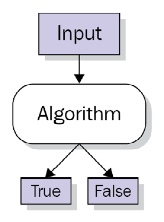
Figure 2.1 – A Boolean circuit gives two opposite variables as output
The basic operations performed in Boolean circuits are as follows:
- AND (conjunction): Denoted with the symbol (X∧Y). This condition is satisfied when X together with Y is true. So, we are dealing with propositions such as pear AND apple, for example. If we are searching some content (let's say a database containing sentences and words), setting the AND operator will select all the elements containing both the words (pear and apple), not just one of them. Now let's explore how this operator works in mathematical mode. The AND operator transposed in mathematics is a multiplication of (X * Y). The following is a representation of the truth table for all the logic combinations of the two elements. As you can see, only when X * Y = 1 does it mean that the condition of conjunction (X∧Y) is satisfied:

Figure 2.2 – Mathematical table for "AND"
- OR (disjunction): Denoted by the symbol (X∨Y). This condition is satisfied when at least one of the elements of X or Y is true. So, we are dealing with a proposition such as pear OR apple. Our example of searching in a database will select all the elements containing at least one of the two words (pear or apple).
In the following table, you can see the OR operator transposed in the mathematical operation (X+Y). At least one of the variables assumes the value 1, so it satisfies the condition of disjunction (X∨Y), represented by the sum of the two variables:

Figure 2.3 – Mathematical table for "OR"
Important Note
Idempotence, from idem + potence (same + power), is a property of certain operations in mathematics and computer science that denotes that they can be applied multiple times without changing the result beyond the initial application. Boolean logic has idempotence within both AND and OR gates. A logical AND gate with two inputs of A will also have an output of A (1 AND 1 = 1, 0 AND 0 = 0). An OR gate has idempotence because 0 OR 0 = 0 and 1 OR 1 = 1.
- NOT (negation): Denoted with the symbol (¬X), meaning X excludes Y. So, we are dealing with propositions such as pear NOT apple. For example, if we search in a database, we are looking for documents containing only the first word or value (pear) and not for the second (apple). Finally, in the following table, you can see represented the NOT operator denoted by the symbol of negation, (¬X). It is represented by a unitary operation that gets back the opposite value with respect to its input:
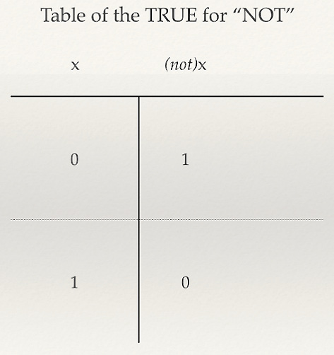
Figure 2.4 – Mathematical table for "NOT"
These basic Boolean operators, AND, OR, and NOT, can be represented by a Venn diagram as follows:

Figure 2.5 – Boolean operators represented by a Venn diagram
Besides the three basic operations just explored, there are more logic operations, including NAND, NOR, and XOR. All these operations are fundamental in cryptography. The NAND logical operator, for example, is used in homomorphic encryption; however, for now, we will limit ourselves to analyzing the XOR operator, also known as exclusive OR.
XOR is also denoted by the symbol ⊕.
The operation of A ⊕ B gives back the logic value of 1 if the number of variables that assume value 1 is odd. In other words, if we consider two variables, A and B, if both are either TRUE or FALSE, then the result is FALSE. As we can see in the following table, when A = 1 and B = 1, the result is 0 (FALSE).
In mathematical terms, XOR is an addition modulo 2, which means adding combinations of 1 and 0 in mod 2, as you can see in the following table, is called exclusive OR (often abbreviated to XOR):

Figure 2.6 – Representing the XOR operations between 0 and 1
The XOR logic operator is used not only for cryptographic algorithms but also as a parity checker. If we run XOR in a logic circuit to check the parity bits in a word of 8 bits, it can verify whether the total number of ones in the word is a pair or not a pair.
Now that we have explored the operations behind Boolean logic, it's time to analyze the first algorithm of the symmetric family: DES.
DES algorithms
The first algorithm presented in this chapter is Data Encryption Standard (DES). Its history began in 1973 when the National Bureau of Standards (NBS), which later became the National Institute of Standards and Technology (NIST), required an algorithm to adopt as a national standard. In 1974, IBM proposed Lucifer, a symmetric algorithm that was forwarded from NIST to the National Security Agency (NSA). After analysis and some modifications, it was renamed DES. In 1977, DES was adopted as a national standard and it was largely used in electronic commerce environments, such as in the financial field, for data encryption.
Remarkable debates arose over the robustness of DES within the academic and professional community of cryptologists. The criticism derived from the short key length and the perplexity that, after a review advanced by the NSA, the algorithm could be subjected to a trapdoor, expressly injected by the NSA into DES to spy on encrypted communications.
Despite the criticisms, DES was approved as a federal standard in November 1976 and was published on January 15, 1977 as FIPS PUB 46, authorized for use on all unclassified data. It was subsequently reaffirmed as the standard in 1983, 1988 (revised as FIPS-46-1), 1993 (FIPS-46-2), and again in 1999 (FIPS-46-3), the latter prescribing Triple DES (also known as 3DES, covered later in the chapter). On May 26, 2002, DES was finally superseded by the Advanced Encryption Standard (AES), which I will explain later in this chapter, following a public competition. DES is a block cipher; this means that plaintext is first divided into blocks of 64 bits and each block is encrypted separately. The encryption process is also called the Feistel system, to honor Horst Feistel, one of the members of the team at IBM who developed Lucifer.
Now that a little bit of the history of this progenitor of modern symmetric algorithms has been revealed, we can go further into the explanation of its logical and mathematical scheme.
Simple DES
Simple DES is nothing but a simplified version of DES. Before we delve into how DES works, let's take a look into this simplest version of DES.
Just like DES, this simplified algorithm is also a block cipher, which means that plaintext is first divided into blocks. Because each block is encrypted separately, we are supposed to analyze only one block.
The key, [K], is made up of 9 bits and the message, [M], is made up of 12 bits.
The main part of the algorithm, just like in DES, is the S-Box, where S stands for Substitution. Here lies the true complexity and non-linear function of symmetric algorithms. The rest of the algorithm is only permutations and shifts over the bits, something that a normal computer can do automatically, so there is no reason to go crazy over it.
An S-Box in this case is a 4X16 matrix consisting of 6 bits as input and 4 bits as output.
We will find that the S-Box is present in all modern symmetric encryption algorithms, such as DES, Triple DES, Bluefish, and AES.
The four rows are represented by progressive 2 bits, as follows:
00
01
10
11
The 16 lines of the columns instead consist of 4 bits in this sequence:
0000 0001 0010 …… …… …… …… 1111
The matrix's boxes consist of random numbers between 0 and 15, which means they never get repeated inside the same row.
In order to better understand how S-Box is implemented and how it works, here is an example: 011011. This string of bits has two outer bits, 01, and four middle bits, 1101.
In this case (working in the binary system, using the N2 notation), (01)2 corresponds to the second row, and (1101)2 corresponds to the 13th column. By finding the intersection of the column and the row, we obtain (1001)2.
You can see the representation in binary numbers of the S-Box matrix described here:

Figure 2.7 – An S-Box matrix (intersection) of 4X16 represented in binary numbers
The same matrix can be represented in decimal numbers as follows:

Figure 2.8 – An S-Box matrix of 4X16 represented in decimal numbers
Here, the number 9 represents the intersection between row 2 and column 13. So, the number found crossing row 2 and column 13, represented in a binary system as (1001)2, corresponds to 9 in the decimal system.
Now that we are clear on what S-Box is and how it is designed, we can see how the algorithm works.
Bit initialization
The message, M, consisting of 12 bits, is divided into two parts, L0 and R0, where L0, the left half, consists of the first 6 bits and R0, the right half, consists of the last 6 bits:
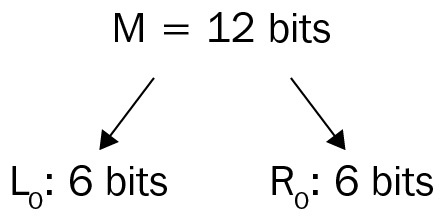
Figure 2.9 – Message (M) is split into 6 bits to the left and 6 bits to the right
Now that we have a clear concept of S-Box and bit initialization, let's proceed with the other phases of the process: bit expansion, key generation, and bit encryption.
Bit expansion
Each block of bits, the left and right parts, is expanded through a particular function that is normally called f.
The DES algorithm uses an expansion at 8 bits (1 byte) starting from 6-bit input for each block of plaintext.
Moreover, DES uses a modality of partition called Electronic Codebook (ECB) to divide the 64 bits of plaintext into 8X8 bits, for each block performing the (Ek) encryption function.
Any f could be differently implemented, but just to give you an example, the first input bit becomes the first output, the third bit becomes the fourth and the sixth, and so on. Just like the following example, let's say we want to expand the 6-bit L0: 011001 input with an expansion function, Exp, following this pattern:
![Figure 2.10 – Bit expansion function [EXP]](https://imgdetail.ebookreading.net/2023/10/9781789617139/9781789617139__9781789617139__files__image__B12111_02_010.jpg)
Figure 2.10 – Bit expansion function [EXP]
As you can see in the preceding figure, L0 = (011001)2 has been expanded with f [12434356].
Then, L0: 011001 will be expanded into (01010101)2, as shown in the following figure:

Figure 2.11 – L0 (011001)2 bit expansion 8 bits
Expanding the 6-bit R0: (100110)2 input to 8 bits with the same pattern, f [12434356], in Ri-1 = (100110)2, we obtain the following:

Figure 2.12 – R0 (100110)2 bit expansion 8 bits
So, the expansion of Ri-1 will be (10101010)2.
Key generation
As we have already said, the master key, [K], is made up of 9 bits. For each round, we have a different encryption key, [Ki], generated by 8 bits of the master key, starting counting from the ith round of encryption.
Let's take an example to clarify the key generation K4 (related to the fourth round):
- K = 010011001 (9-bit key, the master key)
- K4 = 01100101 (8 bits taken by K)
The following figure will help you better understand the process:

Figure 2.13 – Example of key generation
As you can see in the previous figure, we are processing the fourth round of encryption, so we start to count from the fourth bit of master key [K] to generate [K4].
Bit encryption
To perform the bit encryption, (E), we use the XOR function between Ri-1= (100110)2 expanded and Ki = (01100101)2.
I call this output E(Ki):
Exp(Ri-1) ⊕ Ki = 10101010 ⊕ 01100101 = E(Ki) (11001111)
At this point, we split E(Ki), consisting of 8 bits, into two parts: a 4-bit half for the left and a 4-bit half for the right:
L(EKi)= (1100)2 R(EKi)= (1111)2.
Now, we process the 4 bits to the left and the 4 bits to the right with two S-Box 2X8 matrices consisting of 3 bits for each element. The input, as I mentioned earlier, is 4 bits: the first one is the row and the last three represent a binary number to indicate the column (the same as previously, just with fewer bits). So, 0 stands for first and 1 stands for second. Similarly, 000 stands for the first column, 001 stands for the second column, and so on until 111.
We call the two S-Boxes S1 and S2. The following figure represents the elements of each one:

Figure 2.14 – Example of S-Boxes
L (E(Ki)) = (1100)2 is processed by S1; so, the element of the second row, (1)2, and the fourth column, (100)2, is the output, here represented by the number (000)2.
R (E(Ki)) = (1111)2 is processed by S2; so, the element of the second row, (1)2, and the seventh column, (111)2, is the output, here represented by the number (100)2.
Now, the last step is the concatenation of the two outputs obtained, here expressed by the notation ||, which will perform the ciphertext:
S1(L(E(Ki))) = (000)2 || S2(R(E(Ki))) = (100)2
000 || 100 = (000100)2f (Ri-1, Ki) = (000100)2
The following figure shows how the encryption of the first round (the right side) of the function f mathematically works:

Figure 2.15 – Mathematical scheme of (simple) DES encryption at the first round (right side)
Now that we have understood how simple DES works and covered the basics of symmetric encryption, it will be easier to understand how the DES family of algorithms work.
As you have seen, the combination of permutations, XOR and shift, is the pillar of the structure of the Feistel system.
DES
DES is a 16-round encryption/decryption symmetric algorithm. DES is a 64-bit cipher in every sense. The operations are performed by dividing the message, [M], into 64-bit blocks. The key is also 64 bits; however, it is effectively 56 bits (plus 8 bits for parity: 8th, 16th, 24th…). This technique eventually allows us to check errors. Finally, the output, (c), is 64 bits too.
I would like you to focus on the DES encryption scheme of Figure 2.15 to fully understand DES encryption.
Key generation in DES
Based on Shannon's principle of confusion and diffusion, DES, just like most symmetric algorithms, operates over bit scrambling to obtain these two effects.
As already mentioned, the DES master key is a 64-bit key. The key's bits are enumerated from 1 to 64, where every eighth bit is ignored, as you can see in the highlighted column in the following table:

Figure 2.16 – Bits deselected in the DES master key
After the deselection of the bits, the new key is a 56-bit key.
At this point, the first permutation on the 56-bit key is computed. The result of this operation is confusion on the bit positions; then, the key is divided into two 28-bit sub-keys called C0 and D0.
After this operation (always in the same line to create a bit of confusion and diffusion), it performs a circular shift process as shown in the following table:
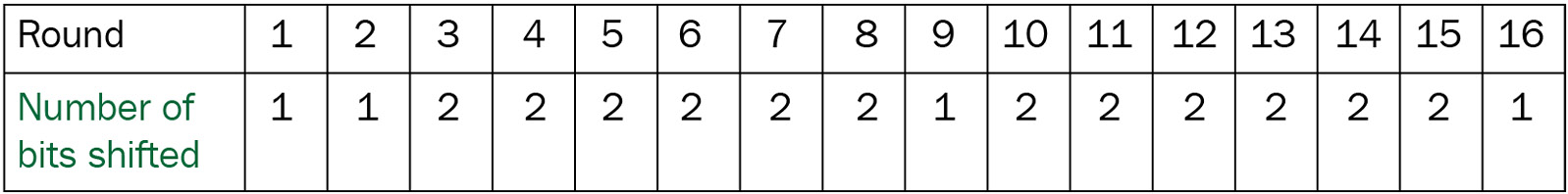
Figure 2.17 – Showing the number of key bits shifted in each round in DES
If you look at the preceding table, you can notice rounds 1, 2, 9, and 16 shift left by only 1 bit; all the other rounds shift left by 2 bits.
Let's take as an example of C0, D0 (the original division of the key in 28-bit left and 28-bit right), expressed in binary notation as follows:
C0 = 1111000011001100101010101001
D0 = 0101010101100110011110001111
Now, from C0 and D0, C1 and D1 will be generated, as follows:
C1 = 1110000110011001010101010011
D1 = 1010101011001100111100011110
If you focus on the step of the generation of C0 --> C1, you can better understand how it works – it's a simple shift to the left of all the bits of C0 with respect to C1:
C0 = 1111000011001100101010101001
C1 = 1110000110011001010101010011
After the circular shift, as explained, the next step is to process a selection of 48 bits over the subset key of 56 bits. It's a simple permutation of position: just to give an example, bit number 14 moves to the first position and bit number 32 moves to the last position (48th). As you can see in the following table, some bits, just like bit number 18, are discarded in the new configuration, so you don't find them in the table. At the end of the process of bit compression, only 48 bits are selected; consequently, 8 bits are discarded:
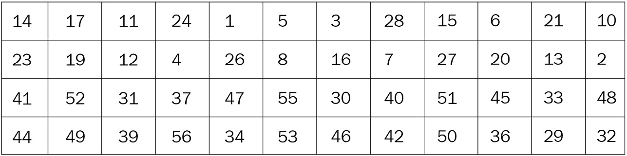
Figure 2.18 – Transformation and compression in a 48-bit subset key
In the following figure, you can see the whole process of key generation, which combines Parity Drop, Shift Left, and Compression:

Figure 2.19 – The key generation scheme
Because of this compression/confusion/permutation technique, DES is able to determine different sub-keys, one per round of 48 bits. This makes DES difficult to crack.
Encryption
After we have generated the key, we can proceed with the encryption of the message, [M].
The encryption scheme of DES consists of three phases:
- Step 1 – initial permutation: First, the bits of the message, [M], are permutated through a function that we call Initial Permutation (IP). This operation from a cryptographic point of view does not seem to augment the security of the algorithm. After the permutation, the 64 bits are divided into 32 bits in L0 and 32 bits in R0 just like we did in simplified DES.
- Step 2 – rounds of encryption: For 0 ≤ i ≤ 16, the following operations are executed:
Li = Ri-1
Compute Ri = Li-1 ⊕ f(Ri-1, Ki).
Here, Ki is a string of 48 bits obtained from the key K (round key j) and f is a function of expansion similar to the f described earlier for simple DES.
Basically, for i = 1 (the first round), we have the following:
L1 = R0
R1 = L0 ⊕ f(R0, K1)
- Step 3 – final permutation: The last part of the algorithm at the 16th round (the last one) consists of the following:
a. Exchanging the left part, L16, with the right part, R16, in order to obtain (R16, L16)
b. Applying the inverse, INV, of the IP to obtain the ciphertext, c, where c = INV(IP (R16, L16))
The following figure is a representation of an intelligible scheme of DES encryption:
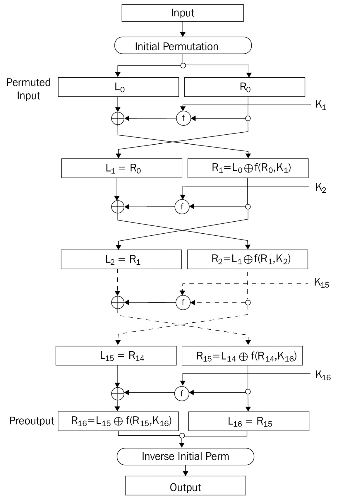
Figure 2.20 – DES encryption
To summarize the encryption stage in DES, we performed a complex process for key generation, where a selection of 48-bit subsection keys on a master key of 64 bits was made. There are consequently three steps: IP, rounds of encryption, and final permutation.
Now that we have analyzed the encryption process, we can move on to DES decryption analysis.
Decryption
DES decryption is very easy to understand. Indeed, to get back the plaintext, we perform an inverse process of encryption.
The decryption is performed in exactly the same manner as encryption, but by inverting the order of the keys (K1…K16) so that it becomes (K16…K1).
In the following figure, you see the decryption process in a flow chart scheme:

Figure 2.21 – DES decryption process
So, to describe the decryption process: you take the ciphertext and operate the first IP on it, then XOR L0 (left part) with R0 = f(R0, K16).
Then you keep on going like that for each round, make a final permutation, and end up finding the plaintext.
Now that we have arrived at the end of the DES algorithm process, let's go ahead with the analysis of the algorithm and its vulnerabilities.
Analysis of the DES algorithm
Going a little bit more into the details of the algorithm, we can discover some interesting things.
One of the most interesting steps of DES is the XOR operation performed between the sub-keys (K1, K2…K16) and the half part of the message, [M], at each round.
In this step, we find the S-Box: the function f previously described in simplified DES.
As we saw earlier, the S-Box is a particular matrix in DES that consists of 4 rows and 16 columns (S-Box 4X16) fixed by the NSA:
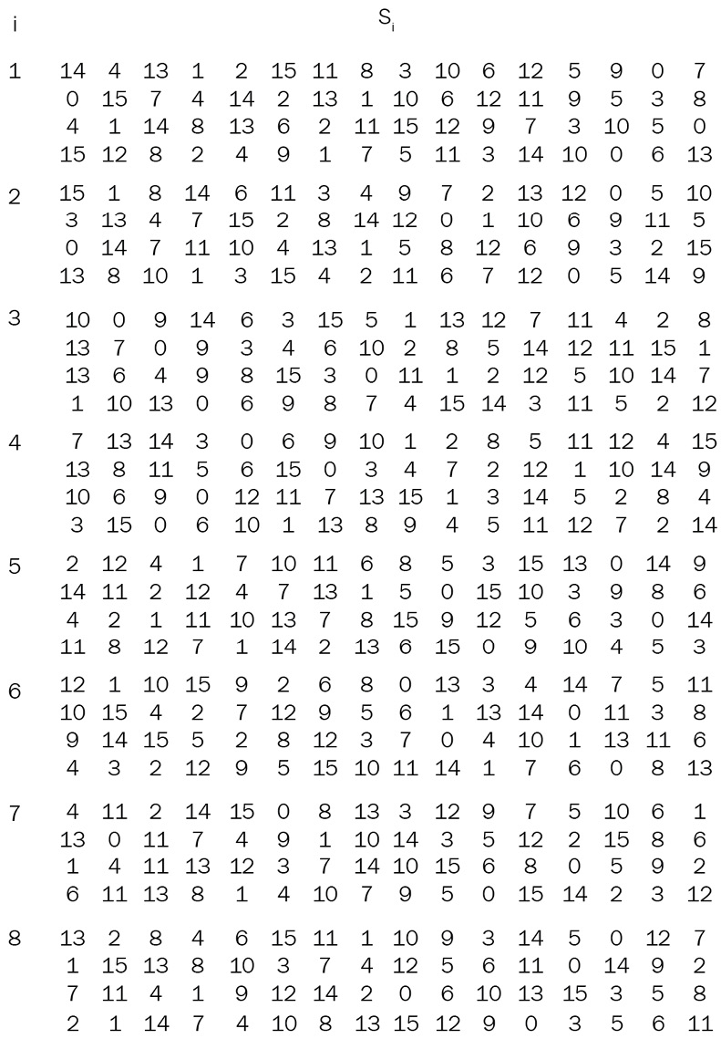
Figure 2.22 – S-Box matrix in DES
Take a look at the specifics of the S-Box in the fifth round of DES:
2, 12, 4, 1, 7, 10, 11, 6, 8, 5, 3, 15, 13, 0 14, 9
14, 11, 2, 12, 4, 7, 13, 1, 5, 0, 15, 10, 3, 9, 8, 6
4, 2, 1, 11, 10, 13, 7, 8, 15, 9, 12, 5, 6, 3, 0, 14
11, 8, 12, 7, 11, 14, 2, 13, 6, 15, 0, 9, 10, 4, 5, 3
As you might notice, the numbers included are between 0 and (Ri-1) 16-1 = 15.
So, 48 bits of input will give exactly 48 bits of output after the XOR operation is performed with [Ki].
Moreover, if you observe carefully, in the 14th column, all the numbers are very low: 0, 9, 3, and 4. Would this combination pose a problem for security?
You will be perplexed if I tell you that it will not be an issue to play with little numbers inside an S-Box.
Another question that may come to you spontaneously might be Why is the key only 56 bits and not 64 bits? Because, as I already mentioned, the other 8 bits are used for pairing.
Actually, the initial master key is 64 bits in length, so every eighth bit of the key is discarded. The final result is a 56-bit key, as you see in the following figure:
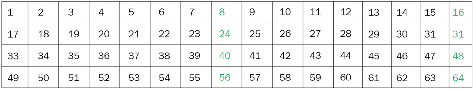
Figure 2.23 – Bit discarded in the DES key generation algorithm
There is one more concern that could arise from the method of encryption adopted in DES. After the IP, as you can see, the bits are encrypted only on the right side through the f(Ri-1, Ki) function. You might ask whether this is less secure than encrypting all the bits. If you analyze the scheme properly, you will notice that at each round, the bits are exchanged from left to right, then encrypted, and vice versa. This technique is like a wrap that allows all the bits to be encrypted, not just the right part as it would seem at first glance.
Looking back at the initial and final permutation functions, you may ask: when making an initial and final inverse permutation, isn't the final result neutral? As I already mentioned, there isn't any cryptographic sense in performing a permutation of bits like that. The reason is that bit insertion into hardware in the 70s was much more complicated than it is now. To complete the discussion, I can say that the entire process adopted in DES for substitution, permutation, E-expansion, and bit-shifting generates confusion and diffusion. At the beginning of this section, I already quoted this concept when I mentioned the security cipher principle identified by Claude Shannon in his A Mathematical Theory of Communication.
Violation of DES
The history of the attacks performed to crack DES since its creation is rich in anecdotes. In 1975, among the academic community, skepticism against the robustness of the key length with respect to the 56-bit keys started to arise. Many articles have been published; one very interesting prediction of Whitney Diffie and Martin Hellman (the same pair from the Diffie and Hellman exchange of the key seen in Chapter 3, Asymmetric Encryption) was that a computer worth $20 million (in 1977) could be built to break DES in only 1 day.
More than 20 years later, in 1998, the Electronic Frontier Foundation (EFF) developed a dedicated computer called DES Cracker to break DES. The EFF spent a little less than $250,000 and employed 37,050 units embedded into 26 electronic boards. After 56 hours, the supercomputer gained the decryption of the plaintext message object of a challenge as there was a $10,000 reward for the decryption of the ciphertext. The method adopted was a simple brute-force method to analyze all the possible combinations of bits given by the 2^56 (about 72 quadrillion) possible keys. The EFF was able to crack DES using hardware that incorporated 1,500 microchips working at 40 MHz, in 4.5 days of running time. Imagine, only 1 microchip would take 38 years to explore the entire set of keys.
At this point, the authorities decided to replace the algorithm with a new symmetric key algorithm, and here came AES. But before exploring AES, let's analyze some possible attacks on DES.
I will present next some possible attacks on DES, taking into consideration that most of these methods are used to attack most symmetric algorithms. Some of the attacks are specific to blocking ciphers, while others are valid for streaming ciphers too. The difference is that in a stream cipher, 1 byte is encrypted at a time, while in a block cipher, ~128 bits are encrypted at a time (block):
- Brute-force attack: This basic method of attack can be performed for any known cipher, meaning trying all the possibilities to find the key. If you recall, the key length of DES is a 56-bit key, which means an attacker would evaluate all the 72,057,594,037,927,936 possibilities (2^56). This is not a computation to be taken lightly, but despite this, DES has been a breakable algorithm since the early 90s.
- Linear cryptanalysis: This is essentially a statistical method of attack based on known plaintext. It doesn't guarantee success every time, but it does work most of the time. The idea is to start from the known input (plaintext) and arrive at determining the key of encryption and, consequently, all the other outputs generated by that key.
- Differential cryptanalysis: This method is technical and requires observing some vulnerabilities inside DES (similar to other symmetric algorithms). This attack method attempts to discover the plaintext or the key, starting from a chosen plaintext. Unlike linear cryptanalysis, which starts from improbable known plaintext, the attacker operates knowing chosen plaintext.
Last but not least, a vulnerability of DES is called weak keys: these keys are simply not able to perform any encryption. This is very dangerous because if applied, you get back plaintext. These keys are well known in cryptography and have to be avoided.
That happens when the sequence of the 16th key (during the key generation) produces all 16 identical keys.
Let's see an example of this problem:
- A sequence of bits all equal to 0000000000000000 or 1111111111111111
- A sequence of alternate bits, 010101010101 or 1010101010101010
In all four cases, it turns out that the encryption is auto-reversible, or in other words, if you perform two encryptions on the same ciphertext, you will obtain the original plaintext.
Triple DES
As I mentioned previously, one of the main weaknesses found in DES was the key length of 56 bits. So, to amplify the volume of keys and to extend their life, a new version of DES was proposed in the form of Triple DES.
The logic behind 3DES is the same as DES; the difference is that here we run the algorithm three times with three different keys.
The following figure shows a scheme proposed to better understand 3DES:

Figure 2.24 – Triple DES encryption/decryption scheme
Let's see how the encryption and decryption stages work in DES, based on the scheme illustrated in the preceding figure.
Encryption in 3DES works as follows:
- Encrypt the plaintext blocks using single DES with the [K1] key.
- Now, decrypt the output of step 1 using single DES with the [K2] key.
- Finally, encrypt the output of step 2 using single DES with the [K3] key.
The output of step 3 is the ciphertext (C).
Decryption in 3DES
The decryption of ciphertext is a reverse process. The user first decrypts using [K3], then decrypts with [K2], and finally decrypts with [K1].
DESX
The last algorithm of the DES family is DESX. This is a reinforcement of DES's key proposed by Ronald Rivest (the same coauthor of RSA).
Given that DES encryption/decryption remains the same as earlier, there are three chosen keys: [K1], [K2], and [K3].
The following encryption is performed:
C = [K3] ⊕ EK1 ([K2] ⊕ [M])
First, we have to perform the encryption (EK), making an XOR between [K2] and the message, [M]. Then, we apply DES, encrypting with [K1] 56 bits. Finally, we add the outputs EK1, XOR, and [K3]. This method allows us to increase the virtual key to be 64 + 56 + 64 = 184 bits, instead of the normal 56 bits:
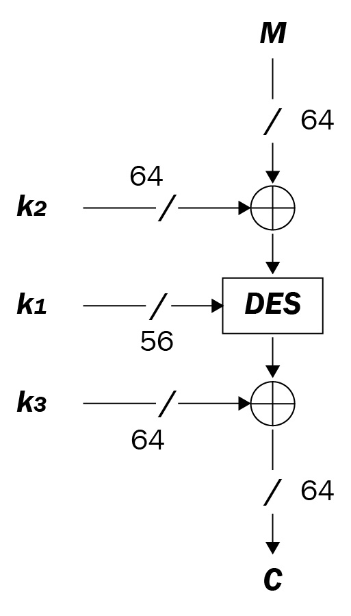
Figure 2.25 – DESX encryption scheme
After exploring the DES, 3DES, and DESX algorithms, we will approach another pillar of the symmetric encryption algorithm: AES.
AES Rijndael
AES, also known as Rijndael, was chosen as a very robust algorithm by NIST (the US government) in 2001 after a 3-year testing period among the cryptologist community.
Among the 15 candidates who competed for the best algorithm, there were five finalists chosen: MARS (IBM), RC6 (RSA Laboratories), Rijndael (Joan Daemen and Vincent Rijmen), Serpent (Ross Anderson and others), and Twofish (Bruce Schneier and others). All the candidates were very strong but, in the end, Rijndael was a clear winner.
The first curious question is about its name: how is Rijndael pronounced?
It's dubiously difficult to pronounce this name. From the web page of the two authors, we can read that there are a few ways to pronounce this name depending on the nationality and the mother tongue of who pronounces it.
Just to start, I can say that AES is a block cipher, so it can be performed in different modes: ECB (already seen in DES), Cipher Block Chaining (CBC), Cypher Feedback Block (CFB), Output Feedback Block (OFB), and Counter (CTR) mode. We will see some better differences between implementations in this section.
AES can be performed using different key sizes: 128-, 192-, and 256-bit. NIST's competition aimed to find an algorithm with some very strong characteristics, such as it should be operating in blocks of 128 bits of input or it should be able to be used on different kinds of hardware, from 8-bit processors (used also in a smart card) to 32-bit architectures, commonly adopted in personal computers. Finally, it should be fast and very robust.
Under certain conditions (that you will discover later), I think this is one of the best algorithms ever; indeed, I have chosen to implement AES 256 in our Crypto Search Engine (CSE). We will see CSE again in Chapter 9, Crypto Search Engine. We adopt AES to secure the symmetric encryption of data encrypted and transmitted between virtual machines that encrypt and store data.
Description of AES
Discussing AES would alone require a dedicated chapter. In this section, I provide an overview of the algorithm. For those of you interested in knowing more, you can refer to the documentation presented by NIST (published on November 26, 2001) reported in the document titled FIPS PUB 197. I am limited in this chapter to describing the algorithm at just a high level and will give my comments and suggestions.
Most importantly, to avoid any confusion, I will analyze AES in a different manner not found in other papers. My analysis of AES will be based on the subdivision of the algorithm into different steps. I have called these steps Key Expansion and First Add Round Key; then, as you will see later on, each step is divided into four sub-steps, called SubBytes transformation, ShiftRows transformation, MixColumn, and AddRoundKey. The important thing is to understand the scheme of the algorithm, then each round works similarly, and you can easily be guided to understand the mechanism of 10 rounds for a 128-bit key, 12 rounds for 192 bits, and 14 rounds for 256 bits.
Key Expansion (KE) works as follows:
- The fixed key input of 128 bits is expanded into a key length depending on the size of AES: 128, 192, or 256.
- Then, the [K1], [K2],…[Kr] sub-keys are created to encrypt each round (generally adding XOR to the round).
- AES uses a particular method called Rijndael's key schedule to expand a short master key to a certain number of round keys.
First Add Round Key (F-ARK) works as follows.
It is the first operation. The algorithm takes the first key, [K1], and adds it to AddRoundKey: using a bitwise XOR of the current block with a portion of the expanded key.
Rounds R1 to Rn-1 work as follows.
Each round (except the last one) is divided into four steps called layers consisting of the following:
- SubBytes (SB) transformation: This step is a fundamental non-linear step, executed through a particular S-Box (we have already seen how an S-Box works in DES). You can see the AES S-Box in the following figure.
- ShiftRows (SR) transformation: This is a scrambling of a bit that causes diffusion on multiple rounds.
- MixColumns (MC) transformation: This step has a similar scope to SR but is applied to the columns.
- AddRoundKey (ARK): The round key is XORed with the result of the previous layer.
The following figure represents S-Box Rijndael expressed in hexadecimal notation:

Figure 2.26 – S-Box Rijndael
The last round runs all the operations of the previous rounds except for layer 3: MC. After all the earlier-mentioned processes are run for each round n times (depending on the size of the key: 14 rounds if the key is 256 bits), AES encryption obtains the ciphertext, (C), as shown in the following figure:

Figure 2.27 – Encryption scheme in AES
Thus, we can re-schematize the entire process of AES encryption in a mathematical function as follows:
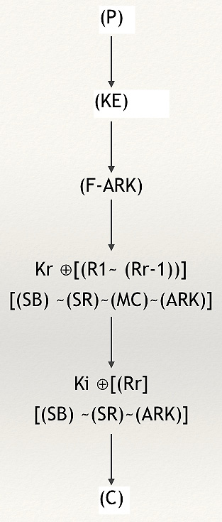
Figure 2.28 – Re-schematizing an AES flow chart with mathematical functions
As you can notice from the proposed scheme in the preceding figure, we have the following:
- Kr ⊕ [(R1~ (Rr-1))] represents all the mathematical processes performed between each round key, (Kr), XORed with the inside functions of each rounds, starting from the first round (after the F-ARK to the last round (excluded)). So, inside [(R1~ (Rr-1))], we find the [(SB) ~(SR)~(MC)~(ARK)] functions.
- In the last round, as you can notice, MC is not present.
In the following figure, you can see the entire process of encryption and decryption in AES:

Figure 2.29 – Encryption and decryption scheme in AES
After schematizing the AES operations of encryption and decryption, we now analyze the attacks and vulnerabilities on this algorithm.
Attacks and vulnerabilities in AES
The NSA and NIST publications deemed AES as invulnerable to any kind of known attack.
However, AES has its vulnerabilities; in fact, every system that can be implemented has vulnerabilities.
Important Note
Recall the NIST document reporting the possible vulnerabilities of AES (documented on October 2, 2000). You can read it at https://www.nist.gov/news-events/news/2000/10/commerce-department-announces-winner-global-information-security.
In the NIST document, it states Each of the candidate algorithms was required to support key sizes of 128, 192 and 256 bits. For a 128-bit key size, there are approximately 340,000,000,000,000,000,000,000,000,000,000,000,000 (340 followed by 36 zeros) possible keys.
However, even though theoretically AES remains unbreakable, (-x%), using all the brute force in the world (you will see a computational analysis of AES in Chapter 9, Crypto Search Engine), it is still always possible to find a breach in any algorithm. It is common to find breaches in the implementation stage. Indeed, pay attention to what happens if you implement, for instance, AES with ECB mode. We have already seen ECB mode in DES. This basic implementation consists of dividing the plaintext into blocks and for each block of plaintext, P, calculating the ciphertext, C:
C = Encr (P)
You can see the scheme of ECB mode encryption in the following figure:

Figure 2.30 – ECB mode encryption
If AES were implemented in EBC mode, as you can see in the preceding figure, in the middle (between the original and the one encrypted with another mode), there could be serious issues. For instance, in the following ECB of Cervino mountain, it's possible to recognize the content even though it's encrypted:

Figure 2.31 – The original picture of Cervino mountain, encrypted with ECB (failure) mode, and encrypted with another block mode
In other words, ECB block mode vanishes the encryption effect, which should have been the same as the third image (encrypted with another block mode).
With another attack on ECB, known as block-reply, knowing a plaintext-ciphertext pair, even without knowing the key, it's possible for someone to repeatedly resend the known ciphertext.
Now, an interesting example of this implication given by ECB mode is presented by Christopher Swenson in his book Modern Cryptanalysis. If Eve (the attacker) tries to trick Bob and Alice during the phase of information exchange, Eve can re-send the block of known plaintext with considerable advantage to herself.
For example, consider this hypothetical scenario related to the ECB attack mentioned previously.
Alice owns a bank account, and she goes to an ATM to withdraw money. It is assumed that the communication between Alice and the bank via the ATM is encrypted, and we suppose it would be encrypted using AES/ECB mode.
So, the encrypted message between Alice (with the key [K]) and the bank is as follows:
- ATM: Encrypt [K] (name: Alice Smith, account number: 123456, amount: $200).
- Let's say that this message encrypted with AES comes out in this form:
CF A3 1C F4 67 T3 2D M9……
- Answer from the bank after having checked the account: [OK].
If Eve is listening to the communication and intercepts the encrypted message, she could just repeat the operation several times until she steals all of Alice's money from the account. The bank would just think that Alice is making several more ATM withdrawals, and if no action is taken against this attack, the victim (Alice) will have just lost all the money in her account. This trick works because Eve resends the same message copied several times. If the [K] key doesn't change for every session of encryption, Eve can attempt this attack. A very efficient solution is to accept only different cryptograms for each session, which gets rid of the use of symmetric encryption for multiple transmissions. Otherwise, in order to prevent this kind of attack, one of the implementations of AES (just like other block ciphers) is CBC.
CBC performs the block encryption generating an output based on the values of the previous blocks.
We will see this implementation again later on, in Chapter 9, Crypto Search Engine, in the Computational Analysis on CSE section, when I present CSE in which we have implemented AES encryption in CBC mode.
Here I'll just explain how it works.
The CBC method uses a 64-bit block size for plaintext, ciphertext, and the initialization vector, IV. Essentially, IV is a random number, sometimes called salt, XORed to the plaintext in order to compute the block.
Just remember the following:
- E = Encryption
- D = Decryption
- C = Ciphertext
Encryption works as follows:
- Calculate the initial block, C0, taking the first block of the plaintext, (P0), XORing with the initialization vector (IV):
C0 = E (P0 ⊕ IV)
- Each successive block is calculated by XORing the previous ciphertext block with the plaintext block and encrypting the result:
Ci = E ( Pi ⊕ Ci-1)
Decryption works as follows:
- To obtain the plaintext, (P0), combine XOR between the decryption of the first block of ciphertext received (C0) and the initialization vector (IV):
P0 = D (C0) ⊕ IV
- To obtain all the other plaintext, (Pi), we have to perform an XOR between the decryption of the ciphertext received, (Ci), and all the other ciphertext excluding the first one:
Pi= D (Ci) ⊕ Ci-1
In the following figure, the scheme of CBC mode encryption is represented:
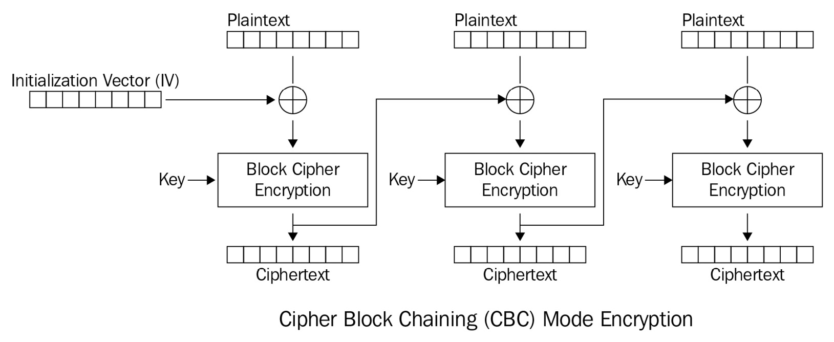
Figure 2.32 – Scheme of CBC mode encryption
AES is a robust symmetric algorithm, and until 2009, the only successful attacks were so-called side-channel attacks. These kinds of attacks are mostly related to the implementation of AES in some specific applications.
Here is a list of side-channel attacks:
- Cache attack: Usually, some information is stored in a memory cache (a kind of memory of second order in the computer); if the attacker monitors cache access remotely, they can steal the key or the plaintext. To avoid that, it is necessary to keep the memory cache clean.
- Timing attack: This is a method that exploits the time to perform encryption based on the correlation between the timing and values of the parameters. If an attacker knows part of the message or part of the key, they can compare the real and modeled executed times. Essentially, it could be considered a physical attack on a bad implementation of the code much more than a logical attack. Anyway, this attack is not only referred to as AES but also RSA, D-H, and other algorithms too, which rely on the correlation of parameters.
- Power monitoring attack: Just like the timing attack, there could be potential vulnerabilities inherent to hardware implementation. You can find an interesting attack experiment at the following link relating to the correlation of the power consumption of an AES 128-bit implementation on Arduino Uno. The attack affected the ARK and SB functions of this algorithm, gaining the full 16-byte cipher key monitoring the device's power consumption. For hardware lovers, this is an exciting attack:
https://www.tandfonline.com/doi/full/10.1080/23742917.2016.1231523
- Electromagnetic attack: This is another kind of attack performed on the implementation of the algorithm. One attack was attempted on FPGA measuring the radiation that emanated from an antenna through an oscilloscope.
Finally, the real problem of AES is the exchanging of the key. This being a symmetric algorithm, Alice and Bob must agree on a shared key in order to perform the encryption and decryption required. Even if AES's few applications could be implemented without any key exchange, most need asymmetric algorithms to make up for the lack of key transmission. We will better understand this concept in the next chapter when we explore asymmetric encryption. Moreover, we will see an application that doesn't need any key exchange in Chapter 9, Crypto Search Engine, when analyzing the CSE.
Summary
In this chapter, you learned about symmetric encryption. We have explored the Boolean operations necessary for understanding symmetric encryption, KE, and S-Box functionality. Then, we deep-dived into how simple DES, DES, 3DES, and DESX work and their principal vulnerabilities and attacks.
After these topics, we analyzed AES (Rijndael), including its implementation schema and the logic of the steps that make this algorithm so strong. Regarding the vulnerabilities and attacks on AES, you have understood how the difference between ECB mode and CBC mode can make it vulnerable to block cipher implementation attacks.
Finally, we explored some of the best-known side-channel attacks valid for most cryptographic algorithms.
These topics are essential because now you have learned how to implement a cryptographic symmetric algorithm, and you have more familiarity with its peculiarities. We will see many correlations with this part in the next chapters. Chapter 9, Crypto Search Engine, will explain CSE, which adopts AES as one of the algorithms for the transmission of encrypted files in the cloud. Now that you have learned about the fundamentals of symmetric encryption, it's time to analyze asymmetric encryption.