CHAPTER FIVE
The Boot Process and the Master Boot Record (MBR)
IN CHAPTER 4, OUR DISCUSSIONS further examined HEX. Also discussed was the relevance of HEX when examining file signature metadata. We noted that some data contained within a file cannot be viewed in a legible or searchable text format such as ASCII or Unicode, specifically data contained within file headers, such as the file signature, thus the necessity of a working knowledge of HEX.
This was made even more apparent as we explored complex files including compound and compressed files, files that contain even more data which is not legible in a text based code, specifically the instructions on how to assemble the complex file. In explaining these file structures we noted that these files needed to be “mounted” in order for the data to be “extracted” or “assembled.”
As we discussed previously, mounting a file is the process of making a file ready to be used by compatible software. The process described by the word “mount” may very well derive its name from a similar process that occurs on a larger, overarching scale with a computer’s operating system. This “system-wide” file-mounting process must occur in order for any data contained within a hard drive to be made accessible, and to be acted upon.
Mounting is the process of taking the raw data contained on a hard drive or other storage media and making it accessible, legible, and useable information. In essence, it is the process of taking the magnetically stored 0s and 1s that are understandable by the machine and converting those to folders and files that are understandable by the machine’s human operator. It is this mounting process, which identifies or defines the boundaries of the computer’s data or file system.
A computer needs to be operational (powered on and running) in order for it to mount a file system. Regardless of whether it’s the file system of the primary hard drive, the file system contained on a CD, or the file system of an external USB hard drive, a computer must be on and running for it to mount the file system.
A computer when first turned on needs to mount a “primary” file system first, a file system containing an operating system by which the computer can be operated. This being the case, and in order to better understand a file system and its structure, it’s best to start from the beginning.
Before a computer can mount its own file system, it must be powered on. The process of turning a computer “on” is oftentimes referred to as “booting up.”
This “booting-up” process and the associated Master Boot Record (MBR), and their importance in understanding the essentials of the cyber forensic process, are the subjects of this chapter.
At times in this chapter we venture specifically into the Basic Input Output System (BIOS) as it pertains to a Windows/IBM PC-based system. In fact, the term BIOS was originally used to describe the startup program of IBM PC-based systems. It has since adopted a broader, nonvendor-specific connotation. All computer models, from IBM compatibles to Unix to MACs, have a BIOS or BIOS type function.
All systems must boot up and all systems have file systems. The boot process as we describe in this chapter may at times target an IBM compatible Windows machine, but the boot process concepts are the same across most operating systems.
The objective in Chapter 5 is to explore the boot process, the BIOS as an element in that boot process, and the overall relationship and relevance of these to cyber forensics.
The reader, aware that there are many operating systems and thus various boot processes, is encouraged to seek out specific vendor documents or specialty, single-focused texts that address the operating system associated with the computer under examination, and to use the material presented in this chapter to establish a basis for an overall understanding of the boot process, BIOS, and the interrelationship to the cyber forensic process.
The process of turning on a system, irrespective of flipping the power switch to “on” and sending electric power to the machine, is often referred to as “booting up.” “Booting up the computer” is a common phrase used to describe the process by which the code necessary to bring the computer to life is initiated.
Being that a computer is logically in the “off” mode prior to being turned on, the start-up process was originally compared to pulling oneself up by one’s own bootstraps, ergo the term “boot”—starting the machine up from an off state.
Thus, the code that allows a computer to pull itself “up” (i.e., to start itself), has since retained the iconic name “bootstrap code.” Bootstrap code is essentially a catalyst, a small program used to initiate or start a larger program.
The concept and details of file systems and their relationship to the cyber forensic process are addressed in a later chapter. For now, let us go back to the beginning and our examination of the boot process.
PRIMARY FUNCTIONS OF THE BOOT PROCESS
Power On Self Test or POST, for short, is a self-diagnostic program used to perform a single test of the CPU, RAM, and various input/output (I/O) devices. The computer hardware is tested to ensure the hardware is functioning properly before the process of loading the operating system is initialized. The POST is performed at startup when the computer is first turned on and is stored in ROM BIOS.
The reader should be aware that the boot process does not necessarily need to directly precede the mounting of a file system.
A file system can be mounted independently of the boot process and the file system can reside elsewhere other than the bootable hard drive. File systems can exist on external USB drives, other areas of the hard drive, and CDs. File systems can be mounted well after a system has been “booted up.” This can be accomplished via various software, including but not limited to specific forensic software.
If file systems are independent of the boot process, why cover the boot process here? To best explain file systems it is best to explain where file systems reside: in partitions and volumes. To explain partitions and volumes we need to first explain how partitions and volumes are “mounted” or “booted.”
BIOS
The BIOS prepares the system for a “known state,” so that software stored on compatible media can be loaded, executed, and given control of the PC.
As explained earlier, the term BIOS was originally coined to describe the boot loading firmware on IBM PC compatible computers. However, the acronym has taken on a more encompassing meaning, and is now used to describe the boot loading firmware of other non-IBM-compatible Operating Systems. Its major functions include:
- Enumerating, testing, and initializing peripheral devices (keyboard, mouse, disk drives, printers, video cards, etc.).
- Loading the operating system (primary file system) into main memory.
After start-up, BIOS programs may manage data flow between the operating system (OS) and the peripherals, so neither the OS nor the application programs need to know the details of the peripherals (such as hardware addresses).
Loading of this firmware is, in part, necessary to prepare the machine into a known state, a state of operational readiness, so that software stored on compatible media can be loaded, executed, and given control of the PC. Once the operating system is loaded into memory there is the potential for data to be saved, stored, altered, or otherwise changed.
At this point in the boot process, if a disk is not write protected then the files being accessed on that file system can and will be altered. It is extremely important to understand that when files are accessed changes occur; metadata such as accessed times and modified times are altered.
BIOS/CMOS Setup Menu
BIOS setup is a program used to display and edit user configurable settings in the BIOS of a PC. On earlier PCs, users had to change a setting when a new drive was added, but auto-detect features were later added. Although many settings are quite arcane and only changed by experienced technicians, users might want to change the boot order of their PCs.
The BIOS setup has also been called the “CMOS setup” or the “CMOS RAM,” because user settings were initially held in a tiny, battery-backed CMOS memory bank that is part of the PC’s real-time clock circuit. Subsequently, more user configuration settings were stored in the BIOS flash memory.
A computer can be made to boot from almost any applicable media such as a floppy, zip disk, CD, DVD, USB device, external hard drive, or the machine’s own internal hard drive. The BIOS enumerates these drives, and their respective boot sequence/order. In other words, the BIOS determines which boot device will load; this is referred to as “first boot sequence.”
The “first boot sequence” is the peripheral order the computer uses to look for the operating system. If it does not find a bootable OS in the first device, it looks to the second and so on. Although computers typically boot from the primary hard disk, the first boot sequence enables it to load a different operating system when necessary by placing a bootable disk into the drive. The first boot sequence is configured in the BIOS and can be changed as needed.
In the early days of personal computers, the floppy disk was chosen as the first device and the hard disk second. Subsequently, the CD-ROM is typically chosen to be the first in line, followed by the floppy and hard disk. Only one device will be accessed and loaded under this boot-up process.
The BIOS, however, can be accessed and changes to the BIOS can be made. These changes take place on a ROM chip and as a result, do not cause anything to be written to the hard drive, where our evidence may be residing.
An understanding of the BIOS is important in the forensic world, as there may be a need to enter the BIOS as part of a cyber forensic investigation. Some reasons include:
- Verify and validate the system clock. The system clock in most machines is not 100 percent accurate; the system clock can potentially loose a number of minutes each day, or stop incrementing the time when the system is turned off. (Refer to Chapter 11 where we discuss the critical role and importance of time in the cyber forensic process.)
The most common cause of this problem is the CMOS battery, which also backs up the date and time so it isn’t lost when the machine is turned off. A weak CMOS battery can lead to problems with the real-time clock, even if the battery isn’t weak enough to cause the loss of BIOS settings. Some motherboards apparently disable the clock as a power-saving measure when the battery voltage gets low. Of course, sometimes the problem with the clock is simply that it is inaccurate.1
- As explained in the BIOS setup menu section, a computer may need to be booted to a stand-alone boot disk. A technical problem with the integrity of the computer’s hard drive may require an alternative boot device, such as an emergency repair disk. Perhaps the most important reason for changing the boot sequence is to prevent the computer from booting up the evidence drive. Why not boot to the evidence drive? Read on!
FORENSIC IMAGING AND EVIDENCE COLLECTION
A digital forensic investigator, as with any investigator, will at times be responsible for collecting and capturing evidence.
Understanding that data can be written to a hard drive (evidence) during the boot process is critical as this process alters the evidence. Knowing when and how data is altered on a piece of evidence (hard drive or otherwise) is not only important when investigating evidence, but also important when acquiring evidence.
As we have discussed, during the boot process of the primary file system (or partition) data is, in most cases, written to the hard drive, such that dates are changed and files are written and altered. It is critical to a sound investigation not to alter evidence for which you have been entrusted to image in a forensically sound manner.
Booting up a computer could very well contaminate the integrity of the data contained within the evidence (hard drive). It would be analogous to a homicide detective stomping through blood splatter at a crime scene. Even if the detective could explain away his/her foot prints, at the very least, the quality of his/her work and competency would be called into question.
A good defense lawyer could quickly and easily discredit an investigation. Questions may arise, such as, “what else did you alter at the crime scene?” and “with such sloppy work, do you even know what other evidence you may have altered?” As you can imagine, even if such mistakes can be explained by an investigator, they can have drastic negative effects and not only prevent critical evidence from being admitted as evidence, but also have the potential to ruin an investigator’s career.
So in an effort to avoid writing data to a piece of evidence an investigator will usually connect a write blocker directly to the evidence hard drive. A write blocker will allow the drive to be powered on and copied, but will block any writing attempts (accidently or intentionally) directly to the evidence drive. (Refer to Chapter 10, Figure 10.15 for an example of a write blocker used to protect original evidence during this process.)
Examples of some write-blocking techniques, although perhaps a bit dated for today’s status of technology include:
- Cassette tapes had a plastic tab that could be broken off to block the write or taping feature on that cassette (See Chapter 10, Figure 10.12.)
- 3½-inch floppy disks with a little plastic tab which could be positioned to write block. (See Chapter 10, Figure 10.13.)
- A CD player without burning abilities is a write blocker, as it cannot write or burn.
- An LP and record player.
A cyber forensic investigator essentially does the same thing when confronted with a hard drive. The only difference is the write blocking equipment is not found at the corner electronic store and can be costly. The investigator essentially connects one end of the write blocker to the Source (evidence hard drive assuming removal from system) and the other end to a Target (storage area—e.g., hard drive, CD, DVD, USB device, etc.).
The write blocker then allows for the hard drive to be powered up and read, but not written to. Data, usually at the bit level as binary, is then “copied” from an evidence drive to the storage area.
In a theoretically perfect environment a hard drive is simply removed from the computer and its potential latent data evidence acquired independently, as described.
However, sometimes this is not possible or practical, as in the case where the hard drive may be so imbedded in a laptop that removing it would require dismantling the laptop, as with some MACs or Sony VAIOs. Other cases that would make removal of the hard drive a less than viable alternative include:
1. A “state-of-the-art” computer containing new hard drive technology with a cutting edge bus adapter (a port which receives data cable) for which there are no write blocker adapters.
2. An older computer with a hard drive for which an adapter may not exist.
3. A server may have multiple hard disk drives (HDD) configured as a single logical hard drive (as in a RAID array). It would be less complicated to acquire this as a single drive (logically) versus removing and acquiring each drive within the array individually, especially if an adapter for a peculiar HDD is not at hand.
Whatever the reason, removing the hard drive and connecting it to a write blocker for imaging may not be an option. When this is the case the computer needs to be powered on, without booting to the hard drive’s operating system thereby avoiding the destruction or tainting of potential evidence. Understanding the BIOS may be extremely beneficial if not imperative when collecting this evidence.
The boot sequence is altered so that the BIOS hands control over to the investigator’s operating system, found on the floppy disk, USB, or compact disc, and not to the operating system found on the hard disk, that is, the evidence. In other words, this allows the system to continue booting via the operating system or utility contained within the boot disk, not relying on use of the internal operating system that is stored on the machine’s internal hard drive. This also allows the cyber forensic investigator access to the data contained on the system without altering the evidence contained within the hard drive.
Some of the BIOS functions or components found in many systems include:
- POST. Test computer hardware, ensuring hardware is properly functioning before starting the process of loading the operating system.
- Bootstrap Loader. The process of locating the operating system. If a capable operating system is located, BIOS will pass the control to it.
- BIOS. Software/Drivers that interface between the operating system and your hardware. When running DOS or Windows you are using complete BIOS support.
- BIOS/CMOS Setup. A configuration program that allows you to configure hardware settings including system settings such as computer passwords, time, and date.2
BIOS SETUP UTILITY: STEP BY STEP
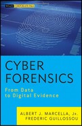
The BIOS is accessed at startup. Soon after a PC is turned on, a short text message typically passes by very quickly on screen indicating which key to press (usually the DEL, F1, or F2 key). A prompt will appear on the screen stating something similar to that shown in Figure 5.1.
FIGURE 5.1 Setting Up Phoenix BIOS
At this point, hitting F2 for this particular IBM compatible system will interrupt the boot process and enter “BIOS.” Different systems will have different keys or key strokes to enter their respective “BIOS.”
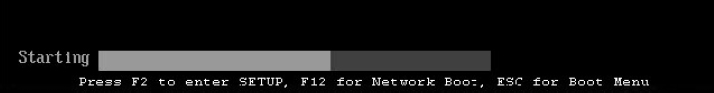
After hitting F2 (or the appropriate function key (e.g., F12, F8, F10, ESC, or DEL), you will be shown the main screen of the BIOS setup utility, which will enable you to access each of the other sections of the BIOS. Figure 5.2 shows a typical BIOS setup screen—Main Tab, for a popular BIOS product, PhoenixBIOS. As we can see, the system time and date can be verified and/or altered.
FIGURE 5.2 BIOS Setup Menu—Main
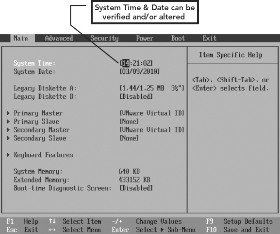
In Figure 5.3, we see the Boot tab. This is where the boot device sequence can be changed. In this example, we see “removable devices” as the first boot device; the hard drive is the second and the CD-ROM is the third.
FIGURE 5.3 BIOS Setup Menu—Boot
The instructions for changing the sequence are usually found on the tab. Here we can see that the positive or plus sign (+) will move the device up in sequence and the negative or minus sign (−) will move the device down in sequence. So, in order to boot this system from a boot disk (CD) the CD-ROM will need to be moved to the top of the boot order.
Figures 5.4 and 5.5 are other examples of BIOS setup menus that you may encounter.
FIGURE 5.4 BIOS Setup Screen Showing First Boot Device (Phoenix Software)
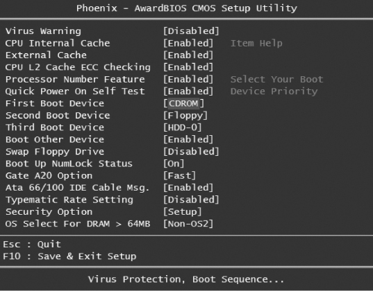
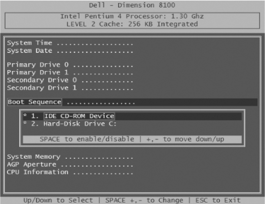
FIGURE 5.5 Dell Dimension BIOS Setup Screen
There are many BIOS versions and varieties, thus the BIOS screen shots shown here may not look similar to the BIOS screens on your system. Also, there are many ways to enter the BIOS—usually F2, but not always! Do your research! Be very careful!
You do not want to skip the BIOS and let the Operating System boot up, resulting in files being accessed and being written to and ultimately changed!
Phase Two of the Boot Process
Once all of the tests ensure that the hardware is properly functioning and before starting the process of loading the operating system, the physical drives are enumerated and the boot code attempts to find and load an operating system or software utility. Once this has transpired the boot process terminates and the primary drive is active.
Writing and changes to the primary drive begin to occur!
Remember, intercepting and accessing the BIOS halts the boot process and prevents the boot code from accessing the active (or primary) drive.
If the boot processes’ “second phase” were allowed to continue with the HDD as the primary boot device, changes would be made to that hard drive, and the result would be an unintended manipulation of data on that hard drive, thus the potential for the destruction or alteration of data, leading to the loss of data integrity in relation to the evidentiary value of data contained on that hard drive.
If the HDD is first in the boot sequence, then the boot code looks there first. Knowing how the BIOS is configured, and the identification of the first boot device, is an essential piece of information for the cyber forensic investigator, in the investigator’s efforts to access the hard drive to be examined while always ensuring the integrity of the data collected.
It is in this second phase of booting that the BIOS contained within these Intel-based computers (or IBM compatible computers) will load the first sector of the hard drive into memory.
This first sector is called the Master Boot Record (MBR). The boot code looks to the very first sector of the default drive (the first drive on the list in the boot sequence in BIOS; see Figure 5.3). This first sector contains the MBR or Master Boot Record.
The MBR contains three components, which we discuss in detail:
1. A small amount of executable code called the master boot code.
2. The disk signature.
3. The partition table for the disk.
The boot loader works by looking for the active partition in the partition table and loading the first sector in that partition. That sector is known as the Partition Boot Record. The Partition Boot Record will then start the process of loading the operating system’s kernel.2
The boot process (code) searches the available drives (already identified in the BIOS) for an operating system. Once found, the operating system tests for the disk signature (a unique number at offset 0x01B8, which identifies the disk to the operating system).
The last two sectors of the MBR contain a two-byte structure called a signature word or end of sector marker, which is always set to 0x55AA (HEX 55AA). A signature word also marks the end of an extended boot record (EBR) and the boot sector. For a validly configured/bootable drive, HEX 55AA must be found in the last two bytes of this sector. The boot code searches for a bootable drive, which is identified by the value 0x55AA.
The master boot code performs the following activities:
1. Scans the partition table for the active partition.
2. Finds the starting sector of the active partition.
3. Loads a copy of the boot sector from the active partition into memory.
4. Transfers control to the executable code in the boot sector.
If the master boot code cannot complete these functions, the system may display one of the following error messages:
- Invalid partition table
- Error loading operating system
- Missing operating system3
Figure 5.6 shows a visual/graphical representation of the First Sectors of a physical hard drive as depicted by the forensic software Encase. Be advised this is only a visual representation of the physical construct of the hard drive.
FIGURE 5.6 Graphical Representation of the First Sectors of a Physical Hard Drive

Each square represents a single sector. How many bytes per sector? Remember from our discussion in Chapter 4, a sector contains 512 bytes.
Figure 5.7 shows further detail of the first sectors of a physical hard drive, indicating the positioning of the MBR, the Volume Boot Record (VBR), and the remaining allocated space on the hard drive.
FIGURE 5.7 Location of the MBR and VBR in the First Sectors of a Physical Hard Drive
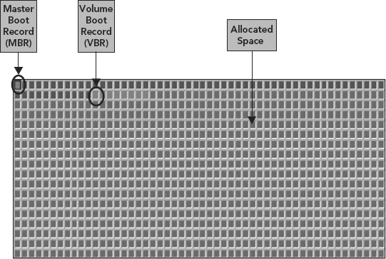
It is important to note that each square shown here represents a single sector (512 bytes).
Remember, that the MBR’s signature bytes are the two final bytes of the first sector, and they are used as a simple validation of the MBR’s contents.4
What’s a HEX Editor? Let’s Review
Certain concepts need to be understood when reading a HEX editor:
1. ACSII (discussed in Chapter 2)
2. HEX (discussed in Chapter 3)
3. Offset (discussed next)
What Is an Offset?
In computer science, an offset within an array or other data structure object is an integer indicating the distance (displacement) from the beginning of the object up (a base address) until a given element or point, presumably within the same object. The concept of distance is valid only if all elements of the object are the same size (typically given in bytes or words).
In this (original) meaning of offset, only the basic address unit, usually the 8-bit byte, is used to specify the offset’s size. In this context an offset is sometimes called a relative address. The absolute address is derived by adding it (the relative address) to the base address.
For example, in Figure 5.8, given an array of characters A containing the contents abcdef, one can say that the element containing the letter “c” has an offset of 2 from the element containing “a.”
FIGURE 5.8 Array of Characters A Containing “abcdef”

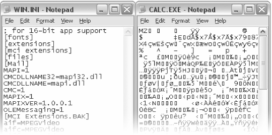
A HEX editor is a computer program used to view and edit binary files. A binary file is a file that contains data in machine-readable form (as opposed to a text file that can be read by a human; see Figure 5.9).5
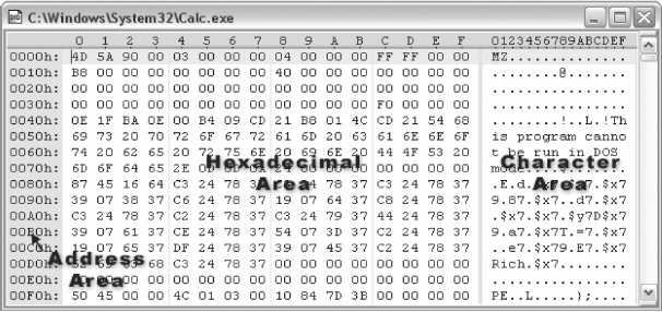
FIGURE 5.9 A Text File Loaded in Notepad on the Left (Human Readable) versus a Binary (Machine Readable) File on the Right
HEX editors allow editing the raw data contents of a file, instead of other programs which attempt to interpret the data for you. Since a HEX editor is used to edit binary files, they are sometimes called a binary editor or a binary file editor. If you edit a file with a HEX editor, you are said to HEX edit the file, and the process of using a HEX editor is called HEX editing.
A typical HEX editor has three areas: an address area on the left, a hexadecimal area in the center, and a character area on the right (see Figure 5.10).6
FIGURE 5.10 A HEX Editor with Addresses on the Left, a Hexadecimal Area in the Middle, and a Character Area on the Right
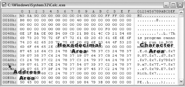
The left pane (address area) displays the byte offset (16 bytes/row), the middle pane (hexadecimal area) displays the two-digit value comprising each byte, and the right pane (character area) shows the ASCII equivalent of each byte of data.
A HEX editor is used mainly for two specific reasons:
1. Analyzing file structure. You can’t see the bytes stored in a file using a regular application to open it. You may need this knowledge to write an application that will interpret the contents of the file. (Cyber forensic investigator’s objective)
2. Editing file contents. This also requires knowledge of the exact file structure. If you don’t know how watermarks are stored in an MPEG file, for example, you could not do anything about them. (Programmer’s objective)
In Figure 5.11, our example shows that there are 16 bytes in each line, the first line contains bytes 0 through 15; the second line’s offset is 16.
FIGURE 5.11 Common HEX Editor Layout
Recall we were discussing the MBR before we took a short deviation to look closer at the HEX editor and the concept of “offsets.” Let us continue on now with further discussion of the MBR. Recapping, the MBR contains three main components:
1. The boot loader
2. The partition table
3. The signature bytes
The boot loader (i.e., bootstrapping) typically loads the main operating system for the computer.
The MBR’s boot loader consists of code that the BIOS loads to boot an operating system. The boot loader works by looking for the active partition in the partition table and loading the first sector in that partition.
That sector is known as the Partition Boot Record and usually (but not always) is an OS’s boot record. The Partition Boot Record will then start the process of loading the operating system’s kernel.
Figure 5.12 displays a graphical representation of the MBR, with the boot loader code highlighted in gray.
FIGURE 5.12 Contents of an MBR with PowerQuest’s BootMagic Code in Its Boot Loader Section (in gray, 000–432)
Source: Adapted from R. Zamora, “Saving and Restoring the Partition Table,” July 24, 2001, retrieved March 2010, www.articles.techrepublic.com, http://articles.techrepublic.com.com/5100-10878_11-1055302.html, used with permission.
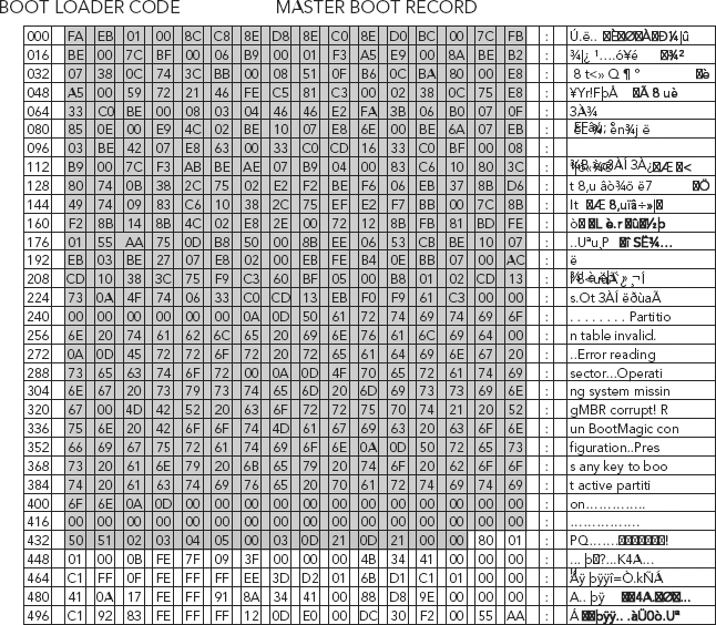
While the boot loader area is always 446 bytes (Byte Offset 0–445), the number of bytes that are actually used for the boot loader code varies with the program that is installed in this area. An MBR created with DOS’s FDISK uses a smaller program in the boot loader area so you will see more 00h bytes.
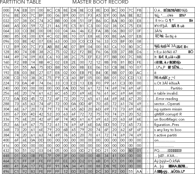
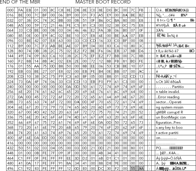
The partition table, which begins immediately after the boot loader area (shown highlighted in gray in Figure 5.13) starts with a value of 0x80 that represents the active (bootable) partition. It contains four descriptors that are 16 bytes long each. The descriptors represent the logical information needed to access a partition on the drive.
FIGURE 5.13 Partition Table of the MBR (in gray 432–496)
Source: Adapted from R. Zamora, “Saving and Restoring the Partition Table,” July 24, 2001, retrieved March 2010, www.articles.techrepublic.com, http://articles.techrepublic.com.com/5100-10878_11-1055302.html, used with permission.
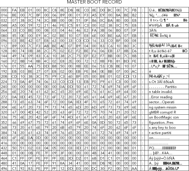
The signature bytes should always be 0x55AA in a valid MBR (shown highlighted in gray in Figure 5.19). It is unlikely that the signature bytes alone will change without other parts of the MBR changing as well. If the signature bytes are not 0x55AA, your hard drive will not boot until they are changed to this hexadecimal number.8
The partition table shown in Figure 5.13 starts with a value of 0x80 that represents the active (bootable) partition. The Partition Table or P-Table contains four descriptors that are each 16 bytes long for a total length of 64 bytes (offsets 446–509). The descriptors represent the logical information needed to access a partition on the drive.7
The Partition Table is a part of the master boot record that describes how the disk is partitioned. The MBR reads the partition table to determine which partition is active (contains the operating system) and where its boot sector is located.
Refer to Figure 5.14 to view the boot flag. The boot flag is set to 0x80 (HEX 80), which is located at offset 446. This is a normal partition record, in a single partitioned hard drive.
FIGURE 5.14 The Boot Flag, within the MBR, Which Is Located at Offset 446
Source: D. Correa, “The Black Art of Data Recovery: BIOS, MBR, VIRUS,” June 13, 2007, DTIDATA, www.DTIDATA.com, retrieved March 2010, www.dtidata.com/resourcecenter/2007/06/22/black-art-data-recovery-mbr-bios-virus-part-2/, used with permission.
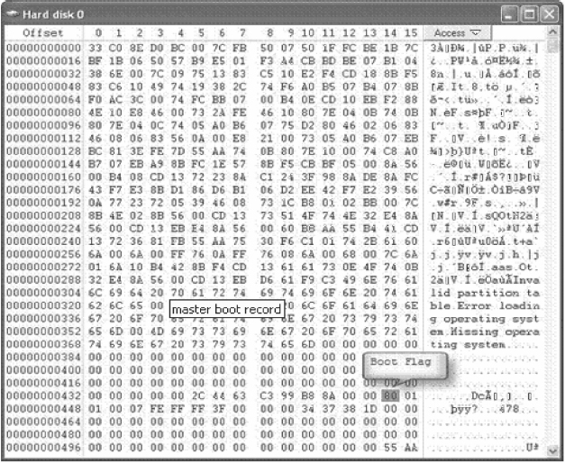
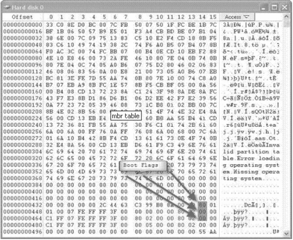
Figure 5.15 shows the MBR for a multi-partitioned drive.
FIGURE 5.15 View of a Multi-Partitioned Drive
Source: D. Correa, “The Black Art of Data Recovery: BIOS, MBR, VIRUS,” DTIDATA, www.DTIDATA.com, June 13, 2007, retrieved March 2010, www.dtidata.com/resourcecenter/2007/06/22/black-art-data-recovery-mbr-bios-virus-part-2/, used with permission.
A hard disk partition is a defined storage space on a hard drive.
Hard drives start with a single “partition” that holds the operating system, your applications, games, music, photos, videos, and all of your important data. Over time, your hard drive becomes very cluttered and messy; you can significantly improve your hard drive’s speed and organization by separating your operating system, applications, and important data into separate partitions on the same drive. This enables your hard drive to find files faster and easier.8
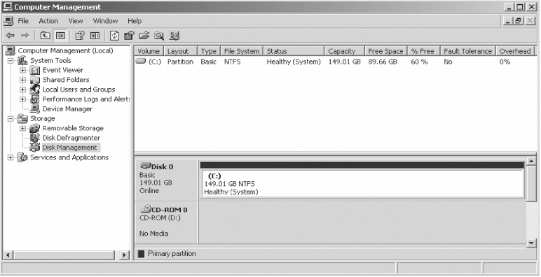
A partition is created when you format the hard disk. Typically, a one-partition hard disk is labeled the “C:” drive (“A:” and “B:” are typically reserved for diskette drives), see Figure 5.16.
FIGURE 5.16 A Single Partitioned Hard Drive
A two-partition hard drive would typically contain “C:” and “D:” drives. (CD-ROM drives typically are assigned the last letter in whatever sequence of letters have been used as a result of hard disk formatting, or typically with a two-partition, the “E:” drive.)
A user may decide to split a hard disk into multiple partitions because smaller partitions often have smaller cluster sizes.
A cluster is the unit of disk space allocation for files and directories. To reduce the overhead of managing on-disk data structures, the filesystem does not allocate individual disk sectors, but contiguous groups of sectors, called clusters.
On a disk that uses 512-byte sectors, a 512-byte cluster contains one sector, whereas a 4-kibibyte (KB) cluster contains eight sectors. (See Figure 5.17.)
FIGURE 5.17 Hard Disk Cluster Size
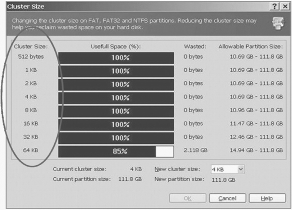
A cluster is the smallest logical amount of disk space that can be allocated to hold a file.
If you have many small files, cluster size is an issue, since regardless of size each file is stored in at least one cluster. This means that a file with one character (five bytes in size) could occupy 16KB of space on the disk.
In a smaller partition, a cluster may only be allocated 4KB. This is an efficient strategy if you are storing a large number of small files.9
Most operating system use the “fdisk” command to create hard disk partitions. (See Figure 5.18.)
FIGURE 5.18 FDISK Partition Editor
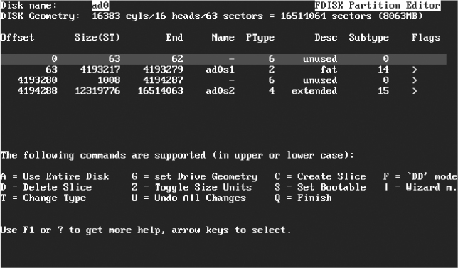
FIGURE 5.19 The End of the MBR—Two-Byte Signature Word (in gray)
Source: Adapted from R. Zamora, “Saving and Restoring the Partition Table,” www.articles.techrepublic.com, July 24, 2001, retrieved March 2010, http://articles.techrepublic.com.com/5100-10878_11-1055302.html, used with permission.
Many operating systems also have graphical tools which accomplish the same task.
What’s a Logical Partition (aka Volume)?
1. A volume is how the operating system (you, me, us, we, etc.) “sees” your free disk space.
2. Volumes (also called logical drives) are represented in Windows by drive letters such as C:, K:, X:, Y:, Z:, and so on.
3. Volumes must be formatted with a file system before data can be stored on them.10
The Signature Word
The signature bytes should always be 0x55AA in a valid MBR (shown highlighted in gray in Figure 5.19).
If the signature bytes are not 0x55AA, your hard drive will not boot until they are changed to this hexadecimal number.11
Summarizing the Boot Process
After turning on your computer, the first thing that happens is that the BIOS (Basic Input Output System) takes control, initializes the screen and keyboard, and tests the main memory. At this point, no storage media or external devices are known to the system.
After that, the system reads the current date and time as well as information about the most important peripheral devices from the CMOS setup. After reading the CMOS, the BIOS should recognize the first hard disk, including details such as its geometry. It can then start to load the operating system (OS) from there.
To load the OS, the system loads a 512-byte data segment from the first hard disk into main memory and executes the code stored at the beginning of this segment. The instructions contained in it determine the rest of the boot process. This is why the first 512 bytes of the hard disk are often called the Master Boot Record (MBR).
Up to this point (loading the MBR), the boot sequence is independent of the installed operating system and is identical on all PCs. Also, all the PC has to access peripheral hardware are those routines (drivers) stored in the BIOS.12
Summarizing the MBR
The MBR contains three main components (see Table 5.1):
1. Boot loader (Byte Offset 0–445)
2. Partition table (Byte Offset 446–509)
3. Signature bytes (Byte Offset 510–511)
TABLE 5.1 Master Boot Record (MBR) Structure of Intel-based Computers
| Byte Offset | Description | Size |
| 0–445 | Boot Loader | 446 Bytes |
| 446–509 | Partition Table | 64 Bytes |
| 510–511 | MBR Signature | 2 Bytes |
| MBR Size | 512 | |
Figure 5.20 shows a graphical representation of the MBR.
FIGURE 5.20 Graphical Representation of the MBR
Source: Adapted from R. Zamora, “Saving and Restoring the Partition Table,” www.articles.techrepublic.com, July 24, 2001, retrieved March 2010, http://articles.techrepublic.com.com/5100-10878_11-1055302.html, used with permission.
1. Boot loader (Byte offset 0–445). The MBR’s boot loader consists of code that the BIOS loads to boot an operating system. The boot loader works by looking for the active partition in the partition table and loading the first sector in that partition. That sector is known as the Partition Boot Record. The Partition Boot Record will then start the process of loading the operating system’s kernel.13
2. Partition table (Byte offset 446–509). 64 bytes in length, consists of four 16 byte entries (4 × 16 = 64). The partition table contains four descriptors that are 16 bytes long each. The table defines or describes the storage space or partition. The descriptors represent the logical information needed to access a partition on the drive.14 The partition table starts with a value of 80 (HEX), which represents the active (bootable) partition.
3. Signature bytes (Byte offset 510–511). The MBR’s signature bytes are the two final bytes of the first sector, and they are used as a simple validation of the MBR’s contents.15 When the MBR is loaded the BIOS checks the last two bytes of the sector. The last two sectors must contain the HEX values 55AA. If this boot record signature is not present, error messages such as “insert boot disk” or “nonsystem boot” will appear.
Understanding that the HEX value 55AA is the boot record signature may not make or break a case. In reality, a cyber forensic investigator may never even find a need to seek out or verify such data.
Why then should we study such meticulous detail?
It is a piece of the puzzle that needs to be understood in order to get a complete understanding of the boot process. As discussed throughout this chapter, a firm understanding of the boot process is necessary if, for one thing, knowing when evidence can, may, or is altered and thereby avoiding contaminating evidence through the imaging process is important.
Understanding the boot process is also important as it will lead us into the next logical step toward gaining a better understanding of cyber forensics: file systems. Chapter 7 will address the next step in the natural progression of accessing information on a system, mounting of the file system.
Chapter 6 focuses on endianness, the attribute of a system that indicates whether integers are represented from left to right or right to left. Knowing how information is written to a disk is very important to the cyber forensic investigator.
1. C. Kozierok, “The System Clock Is Losing Time or Not Keeping Time Accurately,” retrieved March 2010, www.pcguide.com/ts/x/comp/mbsys/cmosLosingTime-c.html.
2. R. Zamora, “Saving and Restoring the Partition Table,” www.articles.techrepublic.com, July 24, 2001, retrieved March 2010, http://articles.techrepublic.com.com/5100-10878_11-1055302.html, used with permission.
3. “Master Boot Record,” Microsoft Technet, retrieved March 2010, http://technet.microsoft.com/en-us/library/cc976786.aspx, used with permission from Microsoft.
4. R. Zamora, “Saving and Restoring the Partition Table.”
5. G. Sweet, “What Is a Hex Editor?” SweetScape Software, 148 Pownal Rd. RR#1, Pownal, PEI, C0A 1Z0, Canada, [email protected], retrieved March 2010, www.sweetscape.com/articles/hex_editor.html, used with permission.
6. Ibid.
7. Ibid.
8. “How Do I Add or Remove a Hard Disk Partition?” retrieved February 2009, www.rickysays.com/add-remove-hard-disk-partitions.
9. “What Is a Hard Disk Partition?” retrieved February 2009, www.tech-faq.com/hard-disk-partition.shtml.
10. Beginners Guides: Formatting and Partitioning a Hard Drive, retrieved February 2009, www.pcstats.com/articleview.cfm?articleID=1778.
11. R. Zamora, “Saving and Restoring the Partition Table.”
12. “Booting and Boot Managers,” chapter 7 in SUSE LINUX—Administration Guide, Novell Corporation, www.novell.com/documentation/suse91/suselinux-adminguide/html/ch07.html, retrieved March 2010.
13. R. Zamora, “Saving and Restoring the Partition table.”
14. Ibid.
15. Ibid.