
CHAPTER SIX
Endianness and the Partition Table
When 900 years you reach, look as good, you will not.
—Yoda
Speak in Big Endian, most of us do.
—Authors
SOME HUMAN LANGUAGES are read and written from left to right; others from right to left; some from bottom to top and others from top to bottom. The order in which data is assembled can vary dramatically from culture to culture, region to region, and country to country.
In the United States and many North American countries, for example, the following date 12/09/12 would represent December 9th, 2012; in the United Kingdom (UK), and many European countries, however, this would represent the date September 12th, 2012. What happened? Why do we have this confusion? This is because the order and interpretation of the numeric values are viewed differently by different society groups.
In the United States the date has been and continues to be traditionally written as MM/DD/YYYY, whereas in many other societies/countries around the globe, representation of the current date is written and viewed as DD/MM/YYYY. That said, even in the United States, the recording and displaying of the date is sometimes shown as DD/MM/YYYY (e.g., U.S. customs immigrations entry forms for all persons arriving into the United States from a foreign country use the DD/MM/YYYY date format). Thus, data representation is not consistent, even within the same country.
In order to correctly interpret these data in the given date format used, the order in which the information is stored and interpreted would need to be known, otherwise the result would be grossly inaccurate. A similar issue arises in the field of computers involving the representation of numbers and their interpretation.
As we have discussed, electronic data is stored at the lowest level in bits, bits are assembled to form bytes, bytes into words, words into dwords, and so on. Endianness of electronic data involves the ordering of these fundamental units. Endianness is the attribute of a system that indicates whether integers are represented from left to right or right to left.
Why then in today’s world of virtual machines and gigahertz processors, would a programmer or a cyber forensic investigator care about such a base-level technical specification? The reason is that endianness must be chosen every time either a hardware or software architecture is designed, and there isn’t much in the way of natural law to help decide or to dictate. So, implementations of endianness vary among hardware manufacturers and software developers.
Generally, in computing, endianness comes in two flavors: big endian and little endian.
In big endian the most significant unit (or byte) of a data field is ordered first, or left justified. With little endian, however, the least significant unit (or byte) of a data field is ordered first with the most significant byte on the right, that is, right justified.
The question may arise, what determines the most significant byte? With bytes, integers, and numbers, in general the first byte is usually the most significant. The first digit will usually have the greatest value. For example, in the U.S. dollar value of $123,456,789.00, which digit in that rather large number is the most important? The one (1) of course, as it represents 100 million. Independently, the nine (9) may be bigger than the 1, but the 9 only represents nine dollars.
In the previous date example, if we were to put the date in a big endian format it would be written as YYYY-MM-DD or 2012-12-09. In this case, a year is a more significant period of time than a day, so being that it is big endian we order the data from most significant to least. The same date written in little endian would therefore be written as DD-MM-YYYY, or 09-12-2012. The date format typically used in the United States (i.e., MM-DD-YY), however, is normally neither; this ordering is sometimes called mixed endian or middle endian.
The following definitions are more precise:
- Big endian exist when the most significant byte of any multibyte data field is stored at the lowest memory address, which is also the address of the larger field.
- Little endian means that the least significant byte of any multibyte data field is stored at the lowest memory address, which is also the address of the larger field.1
Big Endian Example
In big endian, you store the most significant byte in the smallest address. Table 6.1 shows how it would look.
TABLE 6.1 Example of Number Storage Using Big Endianness
| Address | Value |
| 1000 | 90 |
| 1001 | AB |
| 1002 | 12 |
| 1003 | CD |
Little Endian Example
In little endian, you store the least significant byte in the smallest address. Table 6.2 shows how it would look.
TABLE 6.2 Example of Number Storage Using Little Endianness
| Address | Value |
| 1000 | CD |
| 1001 | 12 |
| 1002 | AB |
| 1003 | 90 |
Notice that this is in the reverse order compared to big endian. To remember which is which, recall whether the least significant byte is stored first (thus, little endian) or the most significant byte is stored first (thus, big endian).2
All processors must be designated as either big endian or little endian. Intel’s 80 × 86 processors and their clones are little endian. Sun’s SPARC, Motorola’s 68K, and the PowerPC families are all big endian. The Java Virtual Machine is big endian as well. Some processors even have a bit in a register that allows the programmer to select the desired endianness.
An endianness difference can cause problems if a computer unknowingly tries to read binary data written in the opposite format from a shared memory location or file.
Endianness describes how multibyte data is represented by a computer system and is dictated by the CPU architecture of the system. Unfortunately, not all computer systems are designed with the same Endian-architecture. The difference in endian-architecture is an issue when software or data is shared between computer systems. An analysis of the computer system and its interfaces will determine the requirements of the endian implementation of the software.
Endianness only makes sense when you want to split a large value (such as a word) into several small ones. You must decide on an order to place it in memory.
However, if you have a 32-bit register storing a 32-bit value, it makes no sense to talk about endianness. The register is neither big endian nor little endian. It’s just a register holding a 32-bit value. The rightmost bit is the least significant bit, and the leftmost bit is the most significant bit.
There’s no reason to rearrange the bytes in a register in some other way.
Endianness only makes sense when you are splitting up a multibyte data field, and attempting to store the bytes at consecutive memory locations. In a register, it doesn’t make sense. A register is simply a 32-bit quantity, b31 . . . b0, and endianness does not apply to it.
With regard to endianness, you may argue there is a very natural way to store four bytes in four consecutive addresses, and that the other way looks strange. In particular, it looks “backwards.” However, what’s natural to you may not be natural to someone else. The fact of the matter is that the word is split in four bytes, and most people would agree that you need some order to place it in memory.3
Most Intel-based computers (x86, AMD, etc.) use little endian. Non–Intel based Apple computers and other RISC-based processors for example, use big endian. It is also important to note that network traffic uses big endian ordering.
The origin of the odd terms big endian and little endian can be traced to the 1726 book Gulliver’s Travels, by Jonathan Swift. In one part of the story, resistance to an imperial edict to break soft-boiled eggs on the “little end” escalates to civil war. (The plot is a satire of England’s King Henry VIII’s break with the Catholic Church.)4
In 1981, Danny Cohen, in his paper “On Holy Wars and a Plea for Peace,” using Jonathan Swift’s Gulliver’s Travels as a backdrop for the controversy raging in Lilliput, applied the terms and the satire to the question “What is the proper byte order in messages?” More specifically, the question debated was, “Which bit should travel first—the bit from the little end of the word or the bit from the big end of the word? Cohen concluded that “Agreement upon an order is more important than the order agreed upon.”5
PARTITION TABLE WITHIN THE MASTER BOOT RECORD
In Chapter 5 we discussed the Master Boot Record (MBR) and the data contained within. In cyber forensics, how data is stored on a drive is crucial information, as often, the cyber forensic analyst will have to look at raw data in a HEX editor for possible evidence; thus, knowing how the information is written to disk, big endian or little endian, is very important.
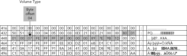
Let’s take a look at the MBR in a HEX editor once again (see Figure 6.1).
FIGURE 6.1 Master Boot Record Displayed in a HEX Editor
Source: Adapted from R. Zamora, “Saving and Restoring the Partition Table,” www.articles.techrepublic.com, July 24, 2001, retrieved March 2010, http://articles.techrepublic.com.com/5100-10878_11-1055302.html, used with permission.
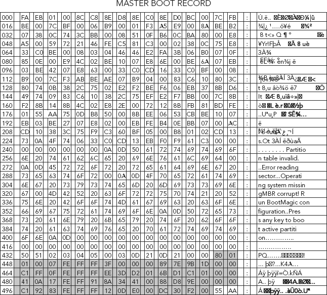
To recap, let’s look at the partition table (highlighted in gray) at byte offsets 446–509. It starts with a value of 80 (HEX) that represents the active (bootable) partition. It contains four descriptors that are 16 bytes long each. The descriptors represent the logical information needed to access a partition on the drive.6
The partition table is divided into four sections or four primary partitions. A primary partition is a partition on a hard drive that can contain only one logical drive (or section). Each section can hold the information necessary to define a single partition, meaning that the partition table can define no more than four partitions.
In the DOS/Windows world, partitions are named using the following method:
- Each partition’s type is checked to determine if it can be read by DOS/Windows.
- If the partition’s type is compatible, it is assigned a “drive letter.” The drive letters start with a “C” and move on to the following letters, depending on the number of partitions to be labeled.
- The drive letter can then be used to refer to that partition as well as the file system contained on that partition.
Each partition table entry contains several important characteristics of the partition:
1. Whether the partition is “active.” (See Figure 6.2.)
2. The location on the disk where the partition starts. (See Figure 6.3.)
3. Total number of sectors contained within the partition. (See Figure 6.4.)
4. The partition’s type. (See Figure 6.5.)
FIGURE 6.2 Active Partition and the Beginning of the Partition Table
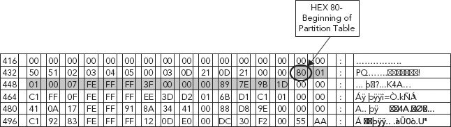
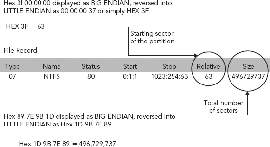
FIGURE 6.3 HEX 3F 00 00 00—Starting Sector of the Partition
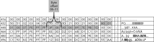
FIGURE 6.4 Total Number of Sectors Contained within the Partition
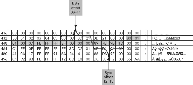
FIGURE 6.5 System ID Field

The “Active” Partition
The partition table contains entries (descriptors) that act as pointers to each of the drive’s partitions (volumes) and contain critical information such as the type of partition, whether or not the partition is active (bootable), where the partition starts and ends, and the size of the partition. Remember, the partition table can point to a maximum of four partitions. (A technique called “extended” partitioning is used to allow more than four, and often times it is used when there are more than two partitions.)
HEX 80 denotes the active partition, at the beginning of the Partition Table, shown in (Figure 6.2). The “active” flag is used by some operating systems’ boot loaders. In other words, the operating system in the partition that is marked “active” is booted.
Take a look at byte offset 08–11 of the first partition (Figure 6.2). In the MBR of a Windows based operating system, this is where we would find the location for the starting sector of this partition.
The Start of the Partition
HEX 3F 00 00 00, as shown in Figure 6.3, depicts the start of the first partition, and is displayed as (or in) BIG ENDIAN format. Reversing this value into LITTLE EDIAN format results in a value of 00 00 00 3F, or after dropping the leading zeros simply HEX 3F.
We are reversing this value (HEX 3F 00 00 00) so we can get to the true value of HEX 3F, which is 63, the value for the starting partition.
One knows when or why this value needs to be reversed just as one knows where to obtain this value in the first place. So one may ask, “How do we know that the HEX 0x80 in the first sector of the partition table identifies the active partition?”
“How do we know where the partition table starts in the first place? How do we know those values identify the starting spot of the partition, much less the order?”
The very nontechnical answer to these very logical and important questions is that we do research and learn. We learn which operating systems store data in which endianness format and commit this to memory. In the end, some things just have to be learned.
So, as we have previously discussed endianness and how the order of numerical values can be reversed, this HEX value needs to be reversed in order to get the correct value. If we don’t reverse the endianness we won’t get the correct data.
Deciphering the Partition’s Hex Starting Value
The HEX value 3F is converted to the decimal value 63, because that is how the system is converting it. It’s just how the system handles this data reference. As the system boots up, it looks to the bytes in this sector and pulls those data that it needs. The system knows what to do with these data because the system is specifically looking for a value of HEX 80.
The system looks to the MBR, in those predefined offsets (bytes 08–11) for HEX 80. When it finds the value it is looking for, HEX 80, it knows it has found the active partition (see Figure 6.2). The same is true for the starting sector (see Figure 6.3); the system looks to those byte offsets to extract data, reverse endian, and convert to decimal. This “process” is included in the instruction set of the boot process itself.
HEX 3F has a decimal equivalent of 63. This decimal value provides us with the relative sector address for the start of the partition.
The Partition’s Size
The multi-byte data field contained within byte offset 12–15 of the partition table defines the number of sectors contained within the partition, in other words, its size (see Figure 6.4).
This HEX value (89 7E 9B 1D in our example) is also “measured” in little endian and converted to a decimal value. This value also defines the last sector of the partition. As we obtained the starting sector from partition table byte offset 8–11, we can simply add the number of sectors to the starting sector and obtain the last sector.
So in this example, 89 7E 9B 1D is the multi-byte data field. We first reverse the order of bytes within this data field (little endian) to 1D 9B 7E 89. Being that this is a multi-byte data field, all the bytes are examined as one. So the data is converted to a decimal value.
1D 9B 7E 89 HEX, converted to its decimal equivalent, equals 496,729,737. This defines the number of sectors, 496,729,737. Since we know that there are 512 bytes per sector, we take the value 496,729,737 and multiply it by 512, and obtain the value 254,325,625,344 bytes.
So we can now conclude that we have a 236 GB (250GB drive).
The Partition’s Type
The partition’s type can be a bit confusing. The type is a number that identifies the partition’s anticipated usage. If that statement sounds a bit vague, that is because the meaning of the partition type is a bit vague.
Some operating systems use the partition type to denote a specific file system type, to flag the partition as being associated with a particular operating system, to indicate that the partition contains a bootable operating system, or some combination of the three.3
The partition type refers to the partition’s relationship with the other partitions on the disk drive. There are three different partition types:
1. Primary partitions (partitions that take up one of the four primary partition slots in the disk drive’s partition table).
2. Extended partitions (developed in response to the need for more than four partitions per disk drive. An extended partition can itself contain multiple partitions, greatly extending the number of partitions possible).
3. Logical partitions (those partitions contained within an extended partition).
Each partition has a type field that contains a code indicating the partition’s anticipated usage. In other words, if the partition is going to be used as Windows NT, the partition’s type should be set to 07 (which is the code representing Windows NTFS).
Table 6.3 shows several partition types associated with specific operating systems and their assigned values.
TABLE 6.3 Partition Types
| Partition Type | Value |
| Empty | 00 |
| DOS 12-bit FAT | 01 |
| DOS 16-bit <=32M | 04 |
| DOS 3.3+ Extended Partition | 05 |
| DOS 3.31+ 16-bit FAT > 32M | 06 |
| Windows NT NTFS | 07 |
| OS/2 Boot Manager | 0a |
| Win95 FAT32 | 0b |
| Win95 FAT32 (LBA) | 0c |
| Win95 FAT16 (LBA) | 0e |
| Win95 Extended (LBA) | 0f |
| Novell | 51 |
| Novell Netware 286 | 64 |
| Novell Netware 386 | 65 |
| Linux native | 83 |
| Linux extended | 85 |
| Partition Magic recovery partition | 3c |
| Xenix Bad Block Table | ff |
To determine the type of partition in use, we look to the System ID field (byte offset 04) within the partition (see Figure 6.5).
For primary partitions and logical drives, the System ID field describes the file system used to format the volume.
Chapter 7 discusses file systems in much greater depth; for now it is important to only know that a file system (sometimes written filesystem) is the way in which files are named and where they are placed logically for storage and retrieval.
The operating system uses the System ID field (see Table 6.4) to determine what file system device drivers to load during startup.
TABLE 6.4 Partition Table Fields
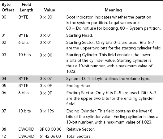
From Table 6.5, we can determine the exact file system used to format the volume.
TABLE 6.5 Values for the System ID Field (byte offset 04)
| Value | Meaning |
| 0 × 01 | 12-bit FAT partition or logical drive. The number of sectors in the volume is fewer than 32,680. |
| 0 × 04 | 16-bit FAT partition or logical drive. The number of sectors is between 32,680 and 65,535. |
| 0 × 05 | Extended partition. |
| 0 × 06 | BIGDOS FAT partition or logical drive. |
| 0 × 07 | NTFS partition or logical drive. |
A review of the Partition Table shown in Figure 6.6 tells us that the volume type is an NTFS partition.
FIGURE 6.6 Byte Offset 04 Value HEX 7 (NTFS partition)
When a hard disk is formatted (initialized), it is divided into partitions or major divisions of the total physical hard disk space. Within each partition, the operating system keeps track of all the files that are stored by that operating system.
Each file is actually stored on the hard disk in one or more clusters or disk spaces of a predefined uniform size. Using NTFS, the sizes of clusters range from 512 bytes to 64 kilobytes.
Read more about file systems and their importance to the cyber forensic investigator in Chapter 7.
In the Windows properties view of the partition (see Figure 6.7), all the characteristics of a partition which have been explained are displayed by the Windows Operating System. Our calculations are now verified, in that:
1. Status = 80—active partition
2. Relative = 63—starting location
3. Size = 496,729,737—in sectors
4. Type = 07—NTFS
FIGURE 6.7 Windows Properties View of the Partition
In cyber forensics, how data is stored on a drive is crucial information, as often, the cyber forensic investigator will have to look at raw data (via a HEX editor) for possible evidence. Thus, knowing how the information is written to disk, and how data are represented and presented physically and logically, is very important.
After touching upon important key concepts in the earlier chapters, such as HEX and binary, it was logical to start at the beginning, with the initial booting of a system. We discussed the importance of the Master Boot Record (MBR) and its contents such as the partition table, and how the system identifies the active partition (HEX 80), its starting sector, and its size.
We deviated from the boot process and delved into endianness in order to understand how a system handles or interprets this data. Being that the endianness or order of data contained within the MBR is subject to such measure, it was imperative to expand upon this essential concept, as we have in this section. Bear in mind endianness is not exclusive to data contained within the MBR. Other data contained within the hard drive is also subject to such measure.
A question may arise, how does the computer know to look at a specific range of bytes in a specific sector? And, how does it know to switch the order? Why wouldn’t it just handle all binary as it comes across it, just like how many humans read, from left to right?
It is important to understand that not all binary data are treated equally. The way in which binary (HEX, in our view) is handled all depends upon the system architecture, or the code. As a system boots it will encounter code that will tell it to go here and do this or that or something else.
The logic loosely interpreted may make better sense to view in this way:
Step 1—go to byte offset 8–11 in the partition table.
Step 2—view these four bytes of data as one value (data field)—Dword.
Step 3—before applying math reverse the order of the bytes—that is, little endian.
Step 4—convert the Dword to a decimal value.
Answer = starting sector of the partition.
How a system knows where to look or how it knows how to compute values is what is known as system architecture. A cyber forensic investigator doesn’t necessarily need to understand all the logic behind the design and architecture of each and every system. What is important is that we can obtain this information through whatever source possible.
The important factor is to confirm, test, and verify those data retrieved. A source may state that the size of a partition can be determined by obtaining a decimal value byte offset 12–15 of the partition table in little endian. It is wise to confirm this with another source, test it, and verify the test. Even if you are 100 percent sure, it is worth testing so that you can fully understand the complexities involved.
Chapter 7 introduces and discusses further the concepts of logical block addresses and file systems, and further investigates the storage and representation of data and its importance to the cyber forensic investigation process and to the cyber forensic investigator.
1. C. Brown and M. Barr, “Introduction to Endianness,” Embedded Systems Programming, 55–56, Netrino, 6030 Marshalee Dr, #355, Elkridge, MD 21075, (866) 783-6233, retrieved April 2010, www.netrino.com/Embedded-Systems/How-To/Big-Endian-Little-Endian, used with permission.
2. C. Lin (2003), University of Maryland, Department of Computer Science, www.cs.umd.edu/class/sum2003/cmsc311/Notes/Data/endian.html, retrieved April 2010.
3. Endianness White Paper, (November 15, 2004), Intel Corporation. www.intel.com/design/intarch/papers/endian.pdf, retrieved April 2010.
4. Brown and Barr, “Introduction to Endianness,” 55–56.
5. D. Cohen (October 1981), “On Holy Wars and a Plea for Peace,” Computer 14, no. 10 (October 1981): 48–54, retrieved April 2010.
6. Brown and Barr, “Introduction to Endianness,” 55–56.
7. “Partitions: Turning One Drive Into Many,” www.centos.org/docs/5/html/5.1/Installation_Guide/s2-partitions-partitioning-x86.html, Red Hat®, Inc., and The CentOS project, released via the Open Publication License, retrieved May 2010.