2
DB2 pureScale Reaches Even Higher
Perhaps next to the BLU Acceleration technology (which we cover in Chapter 3), the most significant enhancements in DB2 10.5 pertain to the DB2 pureScale enhancements. If you’re not familiar with this technology, we give you a brief overview in this chapter. In DB2 10.5, the DB2 pureScale technology gets a major boost in availability from both a planned and unplanned availability perspective with support for DB2’s High Availability Disaster Recovery (HADR) technology, an extension to pureScale’s ultra-available planned maintenance operations to include DB2 Fix Packs, online member add without a backup, and in-place online table reorganization.
In addition, DB2 pureScale gets easier to manage. The multiple commands that are required to implement DB2 Fix Packs are now streamlined into a single command called
installFixPack. There is support for cross-topology backup and restore operations, native multitenancy capabilities, extended support for self-tuning memory manager (STMM) from its previous integration into DB2 pureScale, explicit hierarchical locking (EHL), and more. In this chapter, we detail most of these new features, but we don’t discuss the new DB2 10.5 pureScale support for STMM and online in-place table reorganization because these are long-standing features that are very familiar to DB2 users.In Case It’s Your First Time… Recapping DB2 pureScale
Although it’s outside the scope of this book to fully cover the DB2 pureScale technology—it’s been in the marketplace for over four years now—we want you to understand what it does and how it does it so that you can fully appreciate the significance of the DB2 10.5 enhancements.
In a DB2 pureScale environment, DB2 runs on a cluster of host computers. The DB2 software that runs on a host computer is referred to as a DB2 pure-Scale member, or simply a member. A member is just the
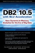
db2sysc process that you’re accustomed to with a “vanilla” DB2 installation. As of DB2 9.5 and later, this process contains all of the agent threads because DB2 is fully threaded on all platforms. The only difference with DB2 pureScale is that you have multiple db2sysc processes (its threads include services for buffer pools, memory regions, log files, and so on), all accessing the same shared copy of the database over different host computers.You can see an example of a pureScale cluster in Figure 2-1. This cluster has four members, which implies that each
db2sysc process runs on its own host computer. The figure includes an “exploded view” of Member 3 to show you what each member contains.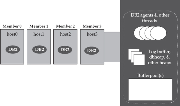
Figure 2-1 The DB2 pureScale member software running on four physical host computers in a DB2 pureScale cluster
When people talk about the pureScale technology, they’ll often use the term “host computer” to represent a physical server in a DB2 pureScale cluster. However, a host computer in a pureScale cluster could just as easily be a virtualized operating system image; for example, by using LPAR (Logical Partition) technology on an IBM Power server. In other words, from a DB2 pureScale perspective, a physical server could have two or more host computers on it.
As previously mentioned, DB2 pureScale runs on multiple host computers that can all access the same shared copy of the database. DB2 pureScale is, therefore referred to as a data-sharing architecture (just like DB2 for z/OS Sysplex), which is very well suited for scaling and keeping transactional workloads available. Each member in a DB2 pureScale cluster has equal access to a shared copy of the database over a storage area network (SAN). In addition, each member can write to its own log files as well as access another member’s log files. This is very important for availability reasons. In Figure 2-2, we add this shared storage to our example DB2 pureScale environment.
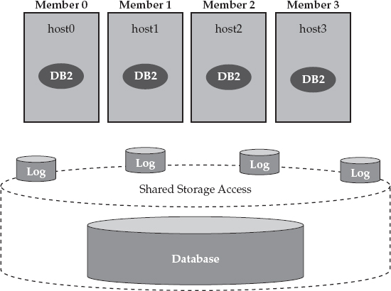
Figure 2-2 DB2 pureScale operates in a shared-everything architecture and, therefore, all members have equal access to a shared copy of the database over a SAN.
DB2 pureScale’s “nervous system” resides in the cluster caching facility (CF). The CF implements global locking services, global buffer management services, and more for a DB2 pureScale cluster; all of this is integral to DB2 pureScale’s industry-leading scalability and availability characteristics.
We round out what a DB2 pureScale environment looks like in Figure 2-3, which shows two CF servers: a primary and a secondary. At a high level, the CFs use their memory to manage the state of the DB2 pureScale cluster by keeping track of global locks and global buffers, among other things, and most of this information is kept up to date synchronously at both the primary and secondary CF servers. If a DB2 pureScale cluster loses its primary cluster caching facility services, it can fail over to the secondary server within a matter of seconds. (Although it’s not recommended for production environments, you can run a DB2 pureScale cluster with just a single CF; this might be appropriate for certain kinds of test environments.)
Figure 2-3 A typical DB2 pureScale solution includes host computers that are running the DB2 pureScale member software as well as primary and secondary CF servers.
In Figure 2-3, you can also see that the primary and secondary CF servers are on their own host computers; however, it’s important to note that these resources can be virtualized as well so that you don’t have to dedicate a physical computer for these services. For example, you could have a DB2 pureScale cluster that consists of two physical computers, with each computer running one (or more) members and either the primary or secondary CF software. In short, to have a two-member DB2 pureScale cluster, you don’t need to have four physically distinct host computers. (We get asked about licensing the CFs a lot, so we’ll add here that you would never have to buy a license for a CF in a DB2 pureScale cluster.)
A DB2 pureScale environment uses a high-speed, low-latency, data-sharing interconnect for all performance-sensitive communications among the cluster’s constituents. DB2 pureScale was engineered to be a different kind of transaction-optimized technology; therefore, it uses remote direct memory access (RDMA), which in itself is a differentiator compared to most database solutions in the marketplace. What’s even more distinguishing is that DB2 pureScale uses interrupt-free RDMA (a differentiating term that we want you to remember when it comes to DB2 pureScale) when processing RDMA requests. You can use any RDMA-capable network; for example, InfiniBand and 10Gb Ethernet with a Mellanox RDMA–capable adapter both qualify. In Figure 2-4, we add a dedicated high-speed interconnect to our DB2 pureScale example environment.
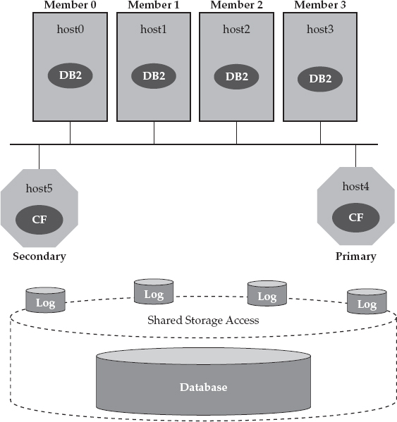
Figure 2-4 In a DB2 pureScale cluster, members and the CF servers communicate with each other over a high-speed interconnect with interrupt-free RDMA for all performance-sensitive communications.
The interrupt-free RDMA that pureScale leverages is the key ingredient in DB2 pureScale’s “secret sauce”: the ability to provide near-linear scaling for many workloads, even when no application affinity is configured. Competitors’ data-sharing databases almost always require that the application be configured to target specific cluster members for different portions of the schema to minimize data-sharing traffic. When it comes to DB2 pureScale, our clients have proven that they see only about a 10 percent difference in scalability between completely affinitized and completely unaffinitized access to a DB2 pureScale cluster running a typical online transaction processing (OLTP) workload. This is a major accomplishment.
So, although it’s always possible to squeeze out every last bit of performance by tying the application access patterns to a database cluster topology (typically required for meaningful scalability when using competing technologies), the difference between the most optimal and the least optimal application access pattern in DB2 pureScale is not large. This is why we say that the DB2 pureScale cluster topology is transparent to applications.
DB2 pureScale also includes an integrated component that we refer to as DB2 Cluster Services. DB2 Cluster Services is a synergistic and enhanced set of three well-proven IBM software components (and then some) that are fully integrated into DB2 pureScale. DB2 Cluster Services performs the following actions:
• Regulates “heartbeats” between members and the CF servers, which includes automatically detecting any component failures in the cluster
• Drives the automation of recovery events that occur when a failure is detected
• Handles the clustering and shared access to shared disk services by using a clustered file system that allows all members to access the shared storage through the clustered file system
• DB2 Cluster Services runs on all the constituents of a DB2 pureScale cluster, as shown in Figure 2-5.
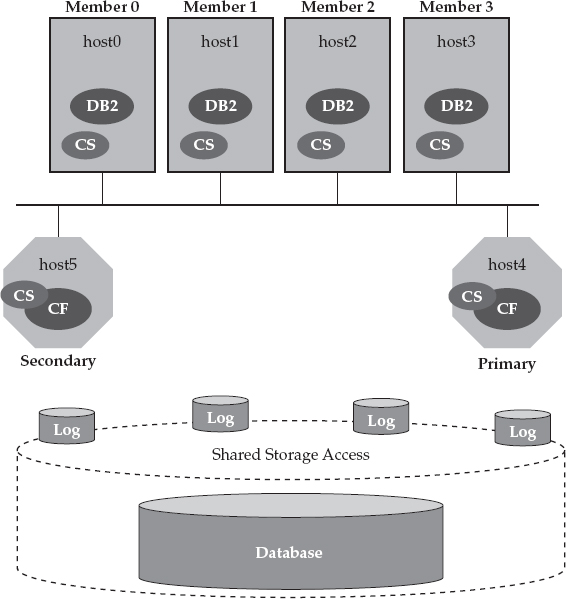
Figure 2-5 DB2 Cluster Services is part of the DB2 pureScale technology’s DNA and provides multiple scalability and availability services to the cluster.
The System z and DB2 for z/OS platforms played an enormous role in the creation of DB2 pureScale. The IBM System Technologies Group (STG) also played a key role in its development. DB2 Cluster Service’s heart-beating capabilities come from IBM Reliable Scalable Cluster Technology (RSCT), which is used in PowerHA SystemMirror (formerly known as HACMP). DB2 pureScale’s clustered file system is the IBM General Parallel File System (GPFS), a highly scalable and reliable file system that is used in many of today’s computing clusters, including massive Hadoop clusters with its GPFS-FPO optimization. Of course, the CF technology itself has the System z Coupling Facility at its roots. Finally, Tivoli System Automation for Multi-platforms (SA for MP) is used for recovery automation and dependency management.
DB2 pureScale’s recovery architecture is almost identical to that of DB2 on System z. A force-at-commit protocol is used so that before a transaction commit is acknowledged to the application, any pages that were updated by that transaction are sent to the CF, and any stale copies of those pages in the local buffer pools of other members are invalidated. Although this is but one example, every aspect of pureScale’s recovery design is carefully optimized for recovery time. The result is a true data-sharing architecture, where surviving members of the cluster can continue to request locks, commit transactions, and read or write pages, even when a member’s host computer fails.
What’s more, pureScale shortens recovery times because it’s able to release very rapidly any locks that are held by in-flight transactions on a failed member. Any transactions waiting for resources that are blocked by those locks can resume quickly. This is possible in a DB2 pureScale cluster because of one of its most differentiating features: There is typically little to no database crash recovery to perform. Folks that have taken the DB2 pureScale technology for a test drive have found that database crash recovery completes in a fraction of the time that they are used to with competitive offerings.
Although there are a lot of different IBM components built into it, DB2 pureScale is one fully integrated solution. When you install DB2 pureScale, all of the “stuff” that we’ve talked about so far in this chapter gets laid down automatically for you across all of the cluster’s host computers. There are no failover scripts to write. And you patch a DB2 pureScale system with a DB2 pureScale Fix Pack, not by applying individual product maintenance.
To finish off our DB2 pureScale environment example, let’s add the clients that connect to the database, as shown in Figure 2-6.
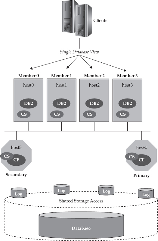
Figure 2-6 Clients connect to a DB2 pureScale cluster and are transparently workload-balanced across the cluster based on algorithms that understand the cluster’s availability and utilization state.
As you can see, clients can connect to any DB2 pureScale member in the cluster. By default, DB2 pureScale balances the workload across members of the cluster according to which member is least loaded. For example, an application might connect to Member 1 and issue a transaction against it, but the next transaction might get routed to Member 3 because Member 3 has a lower load than Member 1. If a member were to fail, the work running on it would be transparently rerouted to a surviving member, so the workload balancer algorithm needs to understand the availability of the cluster. DB2 pureScale can also handle the scenario in which you want to avoid a member that is scheduled for maintenance.
As you can see, the DB2 pureScale development teams partnered very closely with other IBM divisions to bring you this solution. The result is that industry-leading, data-sharing technology has become a first-class citizen in DB2 pureScale. You don’t have to learn nondatabase interfaces to manage the cluster or create a clustered file system; we give you DBA-friendly commands and tooling for that. What’s more, these contributing IBM technologies still exist on their own today, and each has been enhanced in its own right through the development of DB2 pureScale.
Now that you have a good understanding of what DB2 pureScale is, let’s dive into the details of what is being offered in the DB2 10.5 release.
You Can Put DB2 pureScale in More Places
When DB2 pureScale made its debut in the marketplace, it only supported Power AIX. Linux operating system support was added later, but only on IBM System x servers. In addition, only limited interconnect technologies were available (specific kinds of InfiniBand high-speed switches, among others). Although today we recommend that you adopt DB2 pureScale for dead simple application scaling and high availability through the IBM PureData System for Transactions offering, DB2 10.5 vastly opens up the landscape where you can deploy a “roll your own” (RYO) DB2 pureScale environment, and that’s the point of this section.
As of DB2 10.5 Fix Pack 1 (and DB2 10.1 Fix Pack 2), DB2 pureScale is supported on any x86 Intel-compatible, rack-mounted server (including a non-IBM System x server) that supports any of the following InfiniBand QDR or Ethernet RoCE adapters: Mellanox ConnectX-2 EN 10Gb Ethernet Adapters with RoCE, Mellanox ConnectX-2 with Virtual Protocol Interconnect, MT27500 – Mellanox ConnectX-3 EN Dual-Port SFP+ 10Gb Ethernet Adapter, and MT27500 – Mellanox ConnectX-3 VPI QSFP Dual-Port InfiniBand card.
Of course, these requirements are always subject to change, and when they do, the aperture is broadened, so it’s best to check the documentation. However, the point is clear: DB2 pureScale can be deployed in more and more RYO environments with enhancements that were added to this technology since it first became generally available.
DB2 pureScale Gets Even More Available
We’re not kidding when we tell you that we don’t know of a single technology on distributed platforms that can provide better application-transparent scalability and availability for transactional applications.
In fact, we almost feel that we’re doing the pureScale technology a disservice because we intentionally left out details about actual scaling experiences, and restricted ourselves to general statements about what folks are experiencing when they take DB2 pureScale for a test drive. For example, a systems integrator (SI) who provides professional services for a database vendor (that makes some of its clients see red) had the opportunity to test DB2 pureScale. This SI found that DB2 pureScale performed faster and that performance degraded significantly less when adding more nodes (members in DB2 pureScale-speak) to the cluster than was the case for the vendor’s cluster technology. In fact, even when they tuned their application on their de facto technology stack for their “real” application cluster (they hard-coded logic in the application that directed it to a specific node in their cluster to avoid data-sharing performance overhead), DB2 pureScale still outperformed that technology without touching the application (it remained transparent).
Now consider the cost of always having to change your application to grow a cluster. Think about the risk. Now consider an optimal cloud-like environment where you want to leverage a utility-like computing model with elastic scale in a multi-tenant environment. You can’t be changing your application in response to adding or removing computer capacity from the cluster—yet that is exactly what this other technology would have you do. That’s the magic of the DB2 pureScale technology: It yields tremendous performance results with application transparency.
What’s more, this SI found that DB2 pureScale could detect and recover from member failure much more quickly than the competitor’s technology, and it didn’t block I/O to disk during recovery operations—it just blocked access to rows locked by in-flight transactions. If you’re not already familiar with the kind of results that are possible with DB2 pureScale, then this single example should pique your curiosity.
In this section, we detail the DB2 10.5 enhancements that make the pure-Scale technology even more available. DB2 pureScale has a solid reputation for short recovery times from unplanned failures, but in this release, we’ve added a better disaster recovery story, minimization of planned downtimes, and more.
DB2 pureScale Gets High Availability Disaster Recovery
DB2 High Availability Disaster Recovery (HADR) has been a decade-long staple in the DB2 repertoire that provides clients with near-effortless turnkey-like solution for HA or DR. The DB2 10.5 release extends HADR services to DB2 pureScale clusters.
In a non-pureScale clustered DB2 environment (think of a single server running DB2 Enterprise Server Edition, for example), HADR is used to ship database transaction logs at runtime between a primary database (the primary) and a standby database (the standby). The standby receives logs from the primary and replays those logs in real time to keep the standby up to date with the primary. It’s outside the scope of this book to detail how HADR works, so if you need to learn more, check out the DB2 documentation on this topic at http://tinyurl.com/l6zkzto.
This amazing technology is priced right, unlike some other offerings that “guard” the data on a standby database. We often refer to HADR as “availability with clicks of a button.” If you’re familiar with HADR in a DB2 environment, there isn’t much more to learn about it from a pureScale perspective, because HADR behaves in very much the same manner. It’s still simple to set up and configure, and easy to manage. Because a pureScale environment itself is inherently highly available, when HADR is part of a pureScale discussion, it is always in the context of disaster recovery. Of course, the other methods for implementing a disaster recovery solution for DB2 pureScale still exist, namely Q Replication, Change Data Capture (CDC), storage-provided disk replication, and Geographically Dispersed pureScale Cluster (GDPC) among others; HADR adds to this repertoire of options. Although each disaster recovery approach has its advantages and disadvantages, one distinct advantage that HADR provides is simplicity of setup and maintenance.
HADR for pureScale is configured and managed much like HADR in non-clustered DB2 environments. When HADR is used in conjunction with DB2 pureScale, there is a primary HADR cluster (primary cluster) and a secondary HADR standby cluster (secondary cluster), where each cluster is made up of multiple members and its own CFs. You set up an HADR pair in a DB2 pureScale environment in the same manner as in a nonclustered environment, by simply using a backup image from the primary HADR cluster to establish a standby database (by restoring it to the HADR standby cluster). When you configure HADR in a DB2 pureScale environment, the corresponding HADR configuration parameters are set on both the primary and standby pureScale clusters. When you use HADR in a DB2 pureScale environment, the standby must be a pureScale cluster (it can’t just be DB2 Enterprise acting as an HADR standby to a DB2 pureScale cluster, for example) with the same topology (number of members) as the primary. That said, DB2 10.5 does support running more than one member on a physical machine; in other words, the standby cluster doesn’t have to use the same number of physical machines, but it does need the same number of members.
When HADR is started on the standby pureScale cluster, the database is activated on only one member, which has the job of replaying the transaction logs sent from the primary cluster. Each member in the primary cluster ships its logs to the standby replay member through an HADR TCP connection, which handles communication between each member in the primary cluster and the single replay member in the standby cluster. The replay member on the HADR standby cluster is tasked with the job of merging and replaying the log streams.
Just as is the case with HADR in a non-pureScale environment, HADR support for pureScale includes nonforced (role switch) and forced (failover) takeover operations. Figure 2-7 shows a topological representation of HADR technology supporting a DB2 10.5 pureScale cluster. In this figure, the Beaverton DB2 pureScale cluster is operating as the primary cluster and the replay Member 0 on the Toronto-based pureScale HADR standby cluster handles the log replay activity.
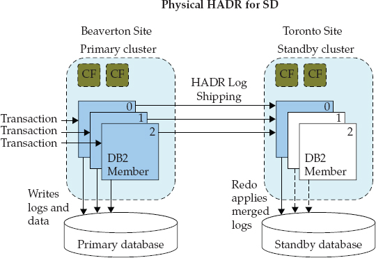
Figure 2-7 The DB2 HADR technology that is used in a DB2 pureScale environment, where Member 0 on the standby pureScale cluster is tasked with the log replay role required to keep the disaster recovery database up to date
DB2 pureScale HADR Synchronization Modes
In DB2 10.5, HADR on DB2 pureScale clusters supports
ASYNC and SUPERASYNC synchronization (sync) modes.In
ASYNC mode, log writes are considered successful only when the log records have been written to the log files on the primary database and delivered to the TCP layer of the primary system’s host machine. In other words, under this mode, the transaction is considered to be complete after the log file has been scheduled for delivery to the standby and hardened on the primary cluster. Because the primary system does not wait for acknowledgment from the standby system, if a failure occurs, transactions might be considered committed when they are still on their way to the standby database. A good analogy here has its roots in a classic spousal disagreement, where one yells from upstairs down to the other in the basement to bring something up. The one spouse knows they sent a message, but was the message even heard? In this mode of HADR, the spousal requester doesn’t wait for an acknowledgment, such as “You bet honey, I’ll get it for you, be right up.” The requesting spouse (we won’t say which one this is) just assumes the message was delivered. (For the record, we don’t recommend this method of communication for marital harmony; we’re more inclined to suggest the synchronous approach.)In
SUPERASYNC mode, log writes are considered successful after they’ve been successfully written to disk on the primary pureScale cluster. In this mode, the HADR pair can never be in PEER state as the transaction logs are shipped to the standby cluster via remote catch up. In our spousal communication analogy, it would be like the example request is considered sent to their spouse by just thinking about it. (We’re certain most married readers have experience in this “What am I, a mind reader”? communication protocol too—also not recommended for marital communications.) This HADR mode is useful if you don’t want transactions to be blocked or to experience elongated response times because of network interruptions or congestion. If you think about it, this would be the fastest-performing mode for HADR, but also comes with the highest probability of transaction loss if the primary system fails because the primary cluster’s database doesn’t wait for acknowledgments from the standby database, as transactions are considered committed regardless of their replication state.ASYNC and SUPERASYNC are typically what clients use when setting up HADR for disaster recovery environments. That’s not the case for high-availability scenarios, which tend to use either SYNC or NEARSYNC, but remember that you’re already getting the utmost in high availability with pureScale itself, so we’re talking about disaster recovery specifically here. Why ASYNC and SUPERASYNC for disaster recovery then? To be prepared for all major types of disasters, you want a fair bit of distance between the two data centers. However, with any type of synchronized replication, the latency introduced due to extended distances between the primary site and the standby site is going to have an impact on the performance of the primary system. For this reason, use of synchronous HADR with “vanilla” DB2 today (NEARSYNC or SYNC) is typically limited to within 60 miles. This makes it a “metro” type of disaster recovery solution, which only protects clients from a limited class of disasters. Another constraint might be the cost of providing the necessary bandwidth and service levels for the pipe between the primary and disaster sites. This is needed for synchronous disaster recovery replication because delays in the data flow have an impact on the performance and responsiveness of the primary site. For these reasons and others, clients often choose an asynchronous disaster recovery solution, and pureScale’s HADR capabilities are a perfect fit. If a client does have a particular need for a synchronous disaster recovery solution between two relatively close sites, other options exist, such as synchronous storage-based replication or Geographically Dispersed pureScale Cluster (GDPC).A DB2 pureScale HADR Example
Consider The Bogey Barn, an online golf retailer that has set up a DB2 pure-Scale environment to support their ordering and fulfillment system. They chose pureScale because it provides exceptional availability (the best that you can get on DB2 and, we believe, in the marketplace). They liked the active-active no I/O-freeze to disk nature of DB2 pureScale technology, which differentiates itself from that other technology we are implicitly referring to in this chapter. Specifically, with DB2 pureScale, cluster member failures don’t cause loss of access to the database.
That said, their DB2 pureScale cluster on its own lacked native disaster recovery capabilities. For example, if their database-hosting site were to encounter a disaster (fire, flood, a major power event, and so on), their database services would be lost. Worse yet, if their storage couldn’t be recovered after the disaster either, massive data loss is possible, which could have serious financial implications to their business. With this in mind, the architectural planning team decided to harden their ordering and fulfillment system by implementing HADR when they migrated to the DB2 10.5 release.
The Bogey Barn’s new disaster-protected pureScale environment includes a primary cluster (Site
A, which houses a single member per physical machine, p0 to p3) and a secondary cluster (Site B, which houses a single member per physical machine, s0 to s3). Although there’s a requirement that each cluster have the same number of members (not physical machines), we recommend that the clusters in such an environment mimic each other because in the event of a failure, users won’t experience performance degradation. After all, if this system is backing your business, it needs to be as responsive after a disastrous event as it was before it. The DB2 instance (whose instance owner is db2inst) houses the myDb database on all hosts (both primary and secondary) in the cluster. TCP port 4000 is used for HADR primary-to-standby communications on all of the hosts, and TCP port 8000 is used for SQL-based client/server communications.The distance between the primary and secondary cluster is 500 miles, and the clusters are connected over a wide area network (WAN) that can support communications at 300Mbit/sec, with round-trip times for network packets of 80 microseconds. The Bogey Barn measured their site’s transactional logging rates over a 24-hour period and observed a total of 1,728GB of log data generated on all log streams, which translates into 20MB/sec at the cluster level and 5MB/sec per stream. A 300Mbit/sec network can support up to 20MB/sec throughput rates, which enables peak logging rates to reach 37MB/sec.
Considering the network characteristics of the WAN and the implicit delay between the primary and secondary clusters, we recommended the
ASYNC synchronization interval in this environment. If network throughput is just above the average logging rate, we would have recommended the SUPERASYNC mode to enable the primary cluster to “get ahead” of the standby cluster during peak transaction times, while letting the secondary cluster “catch up” during nonpeak times; otherwise, the primary cluster’s throughput will be capped at the network send rate during peak times.Each cluster in this environment has a Gigabit Ethernet (GbE) network interface card (NIC) per member that’s dedicated to handling HADR traffic (client/server traffic is handled by another NIC). This is a recommended setup for HADR on both pureScale and non-pureScale systems. The HADR NICs are connected to a router, which connects to the WAN. In this example, for the sake of simplicity,
p0–p3 (for the primary cluster) and s0–s3 (for the secondary cluster) are assumed to be the host names that map to the IP addresses of these dedicated HADR NIC cards, even though the canonical names of these machines might be different.Configuring the Primary and Secondary pureScale Clusters The first step in configuring a pureScale HADR environment is to take an online backup (no downtime is needed) on the primary cluster and to transport that image to the standby site. A subsequent restore operation sets up the HADR pair.
When you configure HADR in a DB2 pureScale environment, there are sets of corresponding HADR configuration parameters that need to be set on both the primary and standby pureScale clusters. Specifically, from a database configuration perspective, you set the following HADR configuration parameters to the same value on each member in the primary DB2 pureScale cluster:
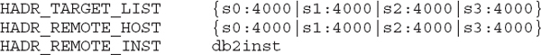
You also set the following parameters on each member (only member
p0 is shown in the following example):And leave the following parameters at their default values:
Use the following command to set the
HADR_LOCAL_HOST variable on all members:This command assumes that
p0–p3 are the canonical names of the hosts (the names returned by the hostname command). If this isn’t the case, you can use a custom script that returns the host name or the IP address that is used for HADR log shipping.Next, set the local HADR service name (
HADR_LOCAL_SVC); by not specifying a specific member number in this command, the configuration parameter will be updated globally for all members:On the standby cluster, set the same initial configuration parameters for each member, as shown in the following example:
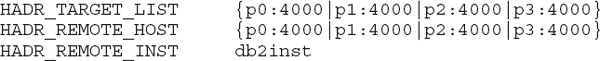
Set the
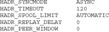
HADR_LOCAL_HOST on the secondary cluster in the same way that you set it on the primary cluster, but use the s0–s3 range this time (one for each member). Moreover, HADR_LOCAL_SVC on the secondary cluster has to match its primary counterpart (set HADR_LOCAL_SVC=4000 on the secondary cluster).Finally, on the secondary cluster, leave the same set of HADR configuration parameters at their default settings as you did for the primary cluster; namely,
HADR_SYNCMODE, HADR_TIMEOUT, HADR_SPOOL_LIMIT, HADR_REPLAY_DELAY, and HADR_PEER_WINDOW.Start Your HADR Engines! After your HADR environment is configured, you’re ready to start up the HADR services and begin data synchronization. To start HADR in support of a pureScale cluster, you initially start it on the standby cluster member that you want to designate as the preferred replay member, using the following command:
Should there be an event that causes the standby cluster to become the primary, you may want to designate a preferred replay member of the current primary, which could find itself in the secondary role. If so, then that is the member on which you want to run the following command, which will start HADR on the primary cluster:
The
START HADR command requires no downtime, and you invoke it when the database is online.NOTE Both primary and standby pureScale clusters will have a designated replay member. If you want to change the designated replay member on the current standby pureScale cluster, you need to deactivate the database on the standby (
DEACTIVATE DATABASE dbname) and then restart HADR on the new preferred member on the standby cluster (START HADR on DATABASE dbname); the START HADR command must be issued on the member that you wish to be the preferred member. Similarly, to change the designated replay member on the current primary (future standby) pureScale cluster, you first have to stop the HADR processes on the primary cluster (STOP HADR on DATABASE dbname) and then start them up again as you did in the previous example, except this time on the new preferred replay member (on the primary cluster) using START HADR on DATABASE dbname; the command is to be issued on the member that is to become the new preferred member. While changing the preferred replay member on either the primary or secondary pureScale cluster, the primary database remains fully available and is processing transactions.After starting HADR to support disaster recovery for a DB2 pureScale cluster, we recommend that you immediately monitor the state of the cluster by issuing the following statement:
This query returns output that is similar to the following example:
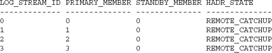
Note that the
STANDBY_MEMBER is 0 on all streams; this is because all primary members connect to the designated standby replay member, which in this case is Member 0.The HADR streams are in
REMOTE_CATCHUP state, which means that any logs generated since the online backup was taken are shipped from the primary cluster to the secondary cluster. After this shipping process reaches “end of log,” the HADR_STATE changes to PEER state. When your HADR cluster is in PEER state, the primary database is fully protected and the standby is now a real-time copy of the primary.Recommendations for the Replay Member and Asymmetric Standby Clusters
Remember that only a single member on the standby cluster replays the logs. For obvious reasons, you might want to consider allocating more CPU and memory resources to the replay member. We’ve seen some “hardware budget challenged” clients configure nonreplay members as logical members that share host machines. The cost of the standby cluster is lower in this case, but in the event of a takeover, the performance of this cluster will be less than that of the original primary cluster. How you approach this is all about your applications and your service level agreement (SLA). Some environments can tolerate performance degradation after a disaster recovery event; but for those that can’t, ensure that the designated replay member has enough resources to handle the task.
When you configure a secondary pureScale cluster as we suggest earlier, it is known as an asymmetric HADR cluster. A DBA might want to allocate only those resources (CPU, memory, and so on) that are required to run workloads on the secondary site until a failover occurs; in this case, the DBA is leveraging the fact that only a single member is used for replay. She might, therefore, virtualize the environment and assign only a fraction of the CPU cores that other inactive standby cluster members would normally have until a failover actually occurs.
Highly Available Replay on a DB2 HADR pureScale Standby Cluster
When HADR is used in a DB2 pureScale environment, it preserves the core design philosophy of highly available database services for the standby cluster. For example, if a member in a standby cluster is performing replay and encounters an outage, DB2 automatically transfers the member’s assigned replay duties to another member on the standby cluster. As long as there is at least one online member in the standby, HADR replay services will continue. In fact, replay is so available, that if you want to completely stop this process, you have to explicitly deactivate it on the standby database.
Figure 2-8 shows a replay member failure and recovery on a standby system in an HADR pureScale cluster. On the left, you can see that only the replay member is active; it is busy replaying the logs that were shipped from the primary system. The lightly shaded fill on the other standby cluster members signifies that they are not active.
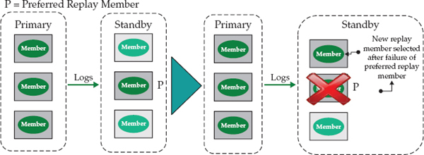
Figure 2-8 Failure of the replay member automatically causes one of the other members to take over and perform log replay on the standby HADR pureScale cluster.
After replay moves away from the preferred replay member (“P” in Figure 2-8), DB2 does not automatically move replay duties back to the preferred member when that member comes back online. For example, perhaps the preferred replay member rebooted abnormally; when the preferred member is available again, it wouldn’t assume its original role until you explicitly run the
DEACTIVATE DATABASE command followed by the ACTIVATE DATABASE command (with appropriate options) on the standby database.If a failure were to occur on the preferred member that’s part of the primary HADR pureScale cluster in Figure 2-8, another member would step up and assume the role of shipping the transaction logs to the replay member on the standby. You can’t control which standby member will assume the role of a failed replay member if such an event were to occur on the primary. DB2 pureScale simply looks at any members on which DB2 is running and randomly picks one.
Automatic Client Reroute in a DB2 pureScale HADR Cluster
Automatic Client Reroute (ACR) is the DB2 technology that is used to reroute DB2 clients from a failed primary server to the standby (which now becomes the primary) in the event of a planned or unplanned failover operation.
Setting up ACR is simple. In our example, you run the following commands on both the primary and secondary pureScale cluster:
The specified
port is the SQL client/server communication port (the database manager configuration name, SVCENAME), not the HADR primary/standby communication port (the database manager configuration name, HADR_LOCAL_SVC).In an ACR-enabled DB2 environment, the first time that a client connects to the primary server (the primary DB2 pureScale cluster in our example), the server returns the addresses of all primary members plus the alternative server address (
s0:8000), which is the Member 0 address of the standby DB2 pureScale cluster. If a client can’t connect to a member on the primary cluster, it tries another, and then another; if it can’t establish a connection to any member of the primary cluster, it tries the standby cluster’s Member 0.For even better availability, we recommend leveraging a connection distributor (or multihome DNS entry) as an alternative server address, which is configured to include multiple members of the alternative server.
Unplanned Failure: Roles Switch in a DB2 pureScale HADR Cluster
If the primary site in a DB2 pureScale HADR cluster fails, you have to explicitly perform a takeover (sometimes this is referred to as a manual takeover) by using the
TAKEOVER HADR command, as shown in the following example:As of the time that DB2 10.5 became generally available, the automated takeover that’s provided by the deeply integrated Tivoli SA MP and that you’re used to seeing in a “vanilla” HADR configuration isn’t supported for HADR when used in a DB2 pureScale environment. For this reason, if you experience or suspect a failure of your primary pureScale cluster, we strongly recommend that you verify that the primary cluster is indeed experiencing an outage.
In our experience, clients typically don’t want automated failover with their disaster recovery environments without their “consent.” There are many reasons for this, and they are all associated with disaster recovery events from which you can recover (the data shop didn’t burn down, but perhaps there was a serious power surge). For example, the disaster recovery site might not have the same “horsepower” as the primary, and certain activities need to be halted on the primary before the critical ones are moved over. Perhaps application servers that are part of the solution are close to the primary, and now that traffic is routed to the secondary (which is further away), performance might be impacted. Clients overwhelmingly told us that their disaster recovery plans are not automated and that they want to be proactively involved in such decisions.
Reintegrating a Primary Server into a DB2 pureScale HADR Cluster If an event takes out the primary pureScale cluster and work is failed over to the secondary (the new primary), at some point you’re going to want to reintegrate the former primary cluster back into the HADR environment. You can do that by using the
START HADR command, as shown in the following example:If reintegration into the HADR cluster is successful, the cluster eventually reaches
PEER state. Then, if you want to revert to the original role that each cluster played before the disaster occurred, you can issue the TAKEOVER HADR command, as shown in the following example:If the reintegration attempt fails, the cluster that you intend to designate as the new standby cluster shuts down, at least initially, and must be re-created from a backup image.
The Planned Failure: Roles Switch in a DB2 pureScale HADR Cluster
One of the great things about HADR is that it enables the seamless takeover of the primary’s role by a standby cluster. This capability is the cornerstone of DB2’s ability to minimize both planned and unplanned downtime. For example, consider a planned maintenance event, such as a weekend power-down of a data center that affects the entire primary cluster. HADR support for a planned noninvasive role switch avoids having to take an outage at the database level for such a planned maintenance event. Use the
TAKEOVER HADR command for such a scenario after the HADR pair is in PEER state.Keep on Rolling, Rolling, Rolling: DB2 Fix Pack Updates Go Online
Since its debut in the DB2 9.8 release, DB2 pureScale has had the ability to support online maintenance; however, this support was limited to non-DB2 maintenance of the solution stack, such as firmware upgrades to the servers, LPARs, or general operating system (OS) fixes. For example, a DBA could identify a target member requiring some sort of maintenance (perhaps an OS patch), gracefully drain activity on that member, remove it from the cluster without impacting any running transactions, perform required maintenance actions, and transparently reintegrate it back into the cluster. When this work was complete, the DBA could move on to the next member and perform the same actions, essentially “rolling” through all of the members in this transparent manner until the maintenance was finished.
The DB2 10.5 release adds support for rolling updates that pertain to DB2 Fix Pack maintenance. This maintenance includes all of the DB2 pureScale software components, such as the DB2 server software itself, the CF software, and all of the integrated cluster services components (RSCT, Tivoli SA MP, and GPFS) that are delivered through the same maintenance pack, not separately.
What’s more, the whole process of implementing a pureScale Fix Pack has been dramatically simplified. Before DB2 10.5, multiple steps were required to apply maintenance to a DB2 pureScale cluster. In DB2 10.1, you had to manually stop the target member, manually put the cluster manager and cluster file system services into maintenance mode, install the Fix Pack, run
db2iupdt, exit maintenance mode, restart the pureScale servers on the member, and so on.In DB2 10.5, all of these steps have been consolidated into a single command called
installFixPack! This command replaces most of the manual steps that you used to perform for pureScale cluster maintenance.A DB2 pureScale Cluster Maintenance Example
Assume that you have a two-member DB2 pureScale cluster to which you want to apply DB2 10.5 Fix Pack 1. This cluster is shown in Figure 2-9. Note that C represents client applications that connect to the cluster (we’re not showing the CF in this figure to keep things simple, but maintenance on the CF works in pretty much the same way—more on that in a bit).
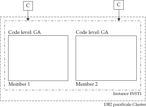
Figure 2-9 A DB2 10.5 pureScale cluster
The first step is to gracefully drain all active queries executing on Member 1. You aren’t going to kill the running transactions—you’re going to let them finish. You do this by invoking the
DB2STOP member1 QUIESCE command. After command execution, DB2 won’t route any new transactions to quiesced Member 1 (Figure 2-10).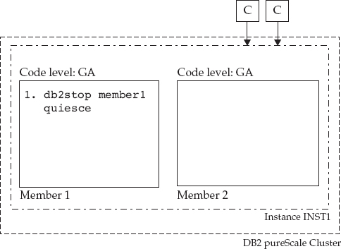
Figure 2-10 Member 1 is quiesced, and eventually all clients connect to Member 2, where all new incoming transactions on this cluster will execute.
It is worthy of note that while we show the use of the
DB2STOP QUIESCE command here explicitly as a separate step, it’s not required (if it isn’t used without any options as is the case in this example) as installFixPack will automatically issue this command. Often users will want to issue a DB2STOP QUIESCE with a timeout option to ensure that only those applications that COMMIT or ROLLBACK during a reasonable period of time are waited on; the rest are forced.Now that Member 1 is “silent” and has no active work, you can invoke a single command to update the DB2-related code components on this member, as shown in Figure 2-11 and in the following example:

Figure 2-11 Maintenance is applied to quiesced Member 1 by using a single command to update all of the DB2-related pureScale software components.
This command updates the binaries on Member 1 for the
inst1 instance to the new DB2 10.5 Fix Pack 1 level (FP1), which could contain maintenance that affects the DB2 engine, the GPFS file system, or the cluster services components (RSCT or Tivoli SA MP), among other components.Member 1 will be automatically reintegrated into the cluster by the
installFixPack command, which will issue a DB2START member1 command under the covers. The pureScale load balancing recognizes that Member 1 has been started and starts to distribute work to it until the cluster is “balanced” from a workload perspective. At this time, because DB2 pureScale is heterogeneous from a DB2 code-level perspective, Member 1 actually runs in a special compatibility mode using the GA code until an explicit COMMIT option is specified on the installFixPack command (more about that later).The same steps are repeated for Member 2 as you “roll” the maintenance through the cluster. During this time, all client connections (C) route to Member 1 in the same way that they routed to Member 2 when maintenance was being applied to Member 1 (what we showed in Figure 2-10).
NOTE Although our running example is using a simple two-node DB2 pureScale cluster, you can extend this scenario to multiple members—up to the maximum 128 members supported by the DB2 pureScale technology. Just continue the rolling process that is outlined here until all members have the Fix Pack 1 binaries installed.
Even though the entire cluster in Figure 2-12 has the Fix Pack 1 binaries running, each member is still executing transactions in compatibility mode with the old (GA) code level—you can’t leverage any new capabilities delivered by the maintenance applied to all of the members until maintenance has been committed to the entire cluster. What’s more, if for any reason a DBA doesn’t want to stay at this code level, she can downgrade to the old (GA) code level, member by member, while online, using steps 1 to 3 in Figure 2-12, so long as the cluster hasn’t been committed to the new maintenance level.
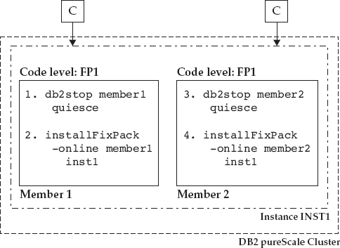
Figure 2-12 Maintenance has been applied (separately, in a rolling fashion) to both members in the cluster. Client connections and incoming work are balanced across the entire cluster. DB2 Fix Pack 1 binaries have been installed on each member.
When you are satisfied with the new Fix Pack code, your final task is to commit the binaries by using the
installFixPack –COMMIT <instance_name> command. This commit operation does exactly what its name implies: It commits the cluster to no longer run in compatibility mode. After you’ve committed the new level to the cluster, you can’t downgrade to the previous binaries (GA level in this example) in a rolling online fashion.The scenario for applying maintenance to the CFs in your cluster is identical; although not explicit in our simplified example, we want to note that you need to upgrade both members and CFs to the same binary level before committing the binaries to the cluster.
So You Want to Roll and Update? Our Best Practices
If you’re going to take advantage of this incredible new feature, we want you to know about some hints, tips, and best practices that we’ve learned along the way:
• You should upgrade only a single machine, virtual session (an LPAR, for example), or host at a time.
• Apply maintenance to the cluster members before you apply it to the CFs.
• When it’s time to apply maintenance to the CFs, apply it to the standby CF before the primary CF. Furthermore, we recommend you apply maintenance to the primary CF during a period of lower activity (if possible) to minimize the impact of primary CF failover, which occurs when DB2 services are stopped on the primary CF. Applications typically won’t notice this slight pause; if the cluster is experiencing overall lower activity during this time, this pause will be even less noticeable.
Adding Members Online
In the spirit of being an elastic, highly available system, DB2 10.5 lets you add new members to a DB2 pureScale cluster without the need to stop other members in the instance or to deactivate the database. Transactions can continue to run on other members while a new member is added to the instance (that is, while a new host is added to the cluster). There is no perceived impact to existing members that are running workloads. Furthermore, the new member can be added to an existing or new member subset (described later in this chapter).
If workload balancing is enabled when the new member starts, clients see this additional cluster capacity and will consider this member in their routing algorithm for new connections or transactions.
Finally, and perhaps most importantly, before DB2 10.5, an offline database backup was required before a new member could be added to ensure DB2 had a recoverability point that included the new member in the backup image. This was required before DB2 10.5 because DB2 backup and recovery services couldn’t roll forward through the add member event, and that’s why you needed a backup image right after you added a new member (and before you ran any new transactions). This way, in the event of a disaster, you’d have a backup to recover from. In DB2 10.5, this requirement has been eliminated.
Cross-Topology Backup and Restore
DB2 10.5 supports cross-topology backup and restore operations that enable you to restore a non-DB2 pureScale backup image (for example, from a nonclustered DB2 Enterprise Server Edition database) to a DB2 pureScale cluster, and the reverse. If you want to restore an image from a non-pureScale environment to a pureScale one (or the reverse), you need to take an offline database backup.
You can also take a DB2 pureScale backup of a subset of members and restore that to a cluster with a superset of members without an offline backup. For example, you could take a backup image from a DB2 pureScale cluster with three members and restore it to a cluster with five members, as shown in Figure 2-13. Note that if you restore an image from a larger cluster to a smaller cluster, you need to take an offline backup … for now.
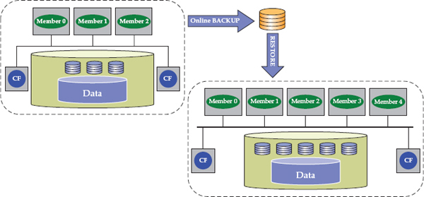
Figure 2-13 Backing up a smaller DB2 pureScale cluster and restoring the image to a larger cluster while online is a nice new feature in the DB2 10.5 release.
There are two common scenarios where we feel that this enhancement is going to be very useful for our clients. The first one is obvious. If you want to migrate your existing DB2 server to a DB2 pureScale cluster, you can do this via backup and restore operations that make short work of this task. Keep in mind that your database has to meet DB2 pureScale requirements for this process to work. For example, DB2 pureScale requires that all table spaces—including those used for the catalog—use automatic storage. (Automatic storage is a requirement for the vast majority of new DB2 features going forward.)
This enhancement is also useful when you want to create a nonproduction version of a DB2 pureScale database in a nonclustered environment for quality assurance or test purposes; after all, in these environments, you might not need a highly scalable active-active environment. For example, some clients choose to mimic a pureScale cluster on a single test machine where they test and practice disaster recovery, while a number of other machines host the same database to support application development. Because one of the virtues of the DB2 pureScale technology is not having to worry about application awareness, moving that code to the pureScale production server is just going to result in faster performance.
The second area where we feel that these new capabilities are going to help our clients is this: You can now restore an online backup image from a point in time before a new member was added to the instance, and then roll forward through the logs to the addition of the new member and beyond—this is a logical extension of DB2 10.5’s support for adding members online in a DB2 pureScale environment.
Workload Consolidation in a DB2 pureScale Environment
DB2 10.5 can provision native multitenancy services to a DB2 pureScale cluster with its new member subset functionality. Before DB2 10.5, it was only possible to configure a workload to be directed to all members (via workload balancing) or to one specific member. The new member subset feature in DB2 10.5 enables the formation of a group (subset) of members to which applications can be directed, and corresponding workloads are balanced only across that defined subset. Figure 2-14 shows a scenario in which different workloads (one is transaction-based and the other is batch-oriented) are balanced among all members in a pureScale instance, the way things were done by default prior to DB2 10.5.

Figure 2-14 Distributing workloads across a DB2 pureScale cluster in the DB2 10.1 release; workloads are directed either to all members or to one member.
With the multitenancy feature in DB2 10.5, you can implement a DB2 pureScale cluster with characteristics such as the one shown in Figure 2-15. A subset (majority) of the cluster is dedicated to handling the transaction-processing workloads (OLTP), and another subset (minority) of the cluster handles batch operations.
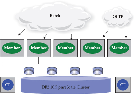
Figure 2-15 Exploiting the multitenancy capabilities of DB2 pureScale 10.5
Creating and expanding subsets across a DB2 pureScale cluster is actually a lot easier than you might think; in fact, the development teams put a lot of work into this to make it a straightforward process. Consider the cluster shown in Figure 2-16.
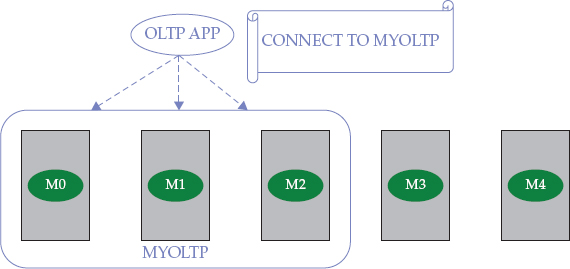
Figure 2-16 Creating a cluster subset to implement a multitenancy strategy in a DB2 pureScale 10.5 environment
In this DB2 pureScale environment, the
OLTP application connects to a member subset called MYOLTP; this subset was created by calling the SYSPROC.WLM_CREATE_MEMBER_SUBSET routine, as shown in the following example:If you want to dynamically add more capacity to this subset online so that the
OLTP application’s work is spread across four members instead of the three that you see in Figure 2-16, call the SYSPROC.WLM_ALTER_MEMBER_SUBSET routine, as shown in the following example:Explicit Hierarchical Locking
Explicit hierarchical locking (EHL) is a feature that’s designed to remove any data-sharing performance overhead for DB2 pureScale tables or table range partitions that are only accessed from a single member. For example, a batch workload that is running on a single member may be updating tables or table range partitions that are not being accessed at the same time by the transactional workload that is running on other members. Another example is where the pureScale cluster is being used as a consolidation platform, hosting multiple databases that are being accessed on different members by their own dedicated applications. If a particular database is only being accessed by its applications through a single member, all of the data access qualifies for EHL. You can enable this EHL feature by setting the new DB2 pureScale
OPT_DIRECT_WRKLD configuration parameter to YES. When this feature is enabled, DB2 automatically monitors and detects whether data sharing is occurring across the cluster’s tables or table range partitions.If DB2 determines that a table or table range partition is being accessed from only a single member (as could be the case in some workload consolidation scenarios), the table or table range partition is placed into EHL mode, which has the effect of suspending the communication of data-sharing information (lock information, page information, and so on) with the CF. If an application spawns activity that causes access to this same table or table range partition on another member in the cluster, the table or table range partition automatically exits EHL mode when this multiple access pattern is detected by DB2.
EHL can deliver a performance boost for certain types of applications that don’t access the broader cluster; however, there is a trade-off: Recovery times are a bit longer because recently committed updates aren’t forced to the CF for tables or table range partitions in EHL mode, as they would be during normal DB2 pureScale operations. In addition, if you’re updating a table or table range partition in EHL mode and the member handling the connection fails, the entire table or table range partition is considered locked during member restart because the CF doesn’t have the fine-grained information that describes which individual record locks were held by in-flight transactions on the failed member.
Wrapping It Up…
As you can see, DB2 10.5 includes major updates to the industry-leading DB2 pureScale software. Although the focus is on even higher levels of availability (HADR and rolling Fix Pack updates are the “eye candy” features), there are also some features that make DB2 pureScale even easier to use: a single command that bundles a set of previous commands for applying maintenance, multitenancy capabilities, and automated locking optimizations for specific workloads.
IBM PureData System for Transactions is the member of the IBM PureSystems family that includes the DB2 pureScale software in a tightly packed modality that provides a highly reliable and scalable database platform designed to help flatten complexity, accelerate time to value, and lower ongoing data management costs. This expertly integrated system enables IT departments to easily deploy, optimize, and manage transactional database workloads, and sets a new standard for workload-optimized systems.
IBM PureData System for Transactions is industry recognized for its four virtues: speed, simplicity, scalability, and smarts. Specifically, the industry-leading DB2 pureScale software provides this solution with database recovery times that are measured in seconds. It’s considered simple because it’s more than just an appliance. It’s an entire ecosystem with an A–Z management toolset that enables you to deploy expert-built patterned databases in minutes, as opposed to weeks, months, or more. IBM PureData System for Transactions is highly scalable because it lets you grow the system from small to medium to large deployments without any planned downtime. Finally, it’s smart because it supports Oracle database applications with minimal changes (it also supports DB2 applications without any changes too) in addition to a host of other smart features.
The built-in database management expertise in IBM PureData System for Transactions enables the system to do many of the ongoing administration tasks automatically, freeing up database staff from routine work. The fact that it’s integrated by design results in factory-optimized systems that are designed for high reliability and scalability out of the box, streamlining system integration efforts. These systems provide a simplified experience from design to purchase to maintenance, which helps reduce total cost of operations. IBM PureData System for Transactions represents the future of data services delivery and management. It combines the simplicity of a workload-optimized appliance with the flexibility of tailor-made systems, providing both fast time to value and customization to meet specific business needs.
Some of the features that are described in this chapter have already made their way into IBM PureData System for Transactions, others are on the way. This great example of flattening the time to success is brought to you by the world’s most sophisticated, available, and scalable distributed transaction system in today’s marketplace.
..................Content has been hidden....................
You can't read the all page of ebook, please click here login for view all page.