Chapter 3
Understanding Networking Data Sources
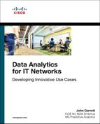
This chapter begins to examine the complexities of networking data. Understanding and preparing all the data coming from the IT infrastructure is part of the data engineering process within analytics solution building. Data engineering involves the setup of data pipelines from the data source to the centralized data environment, in a format that is ready for use by analytics tools. From there, data may be stored, shared, or streamed into dedicated environments where you perform data science analysis. In most cases, there is also a process of cleaning up or normalizing data at this layer. ETL (Extract, Transform, Load) is a carryover acronym from database systems that were commonly used at the data storage layer. ETL simply refers to getting data; normalizing, standardizing, or otherwise manipulating it; and “loading” it into the data layer for future use. Data can be loaded in structured or unstructured form, or it can be streamed right through to some application that requires real-time data. Sometimes analysis is performed on the data right where it is produced. Before you can do any of that, you need to identify how to define, create, extract, and transport the right data for your analysis, which is an integral part of the analytics infrastructure model, shown in Figure 3-1.
Chapter 2, “Approaches for Analytics and Data Science,” provides an overlay example of applications and analytics that serves as a backdrop here. There are layers of virtual abstraction up and down and side by side in IT networks. There are also instances of applications and overlays side by side. Networks can be very complex and confusing. As I journeyed through learning about network virtualization, server virtualization, OpenStack, and network functions virtualization (NFV), it became obvious to me that it is incredibly important to understand the abstraction layers in networking. Entire companies can exist inside a virtualized server instance, much like a civilization on a flower in Horton Hears a Who! (If you have kids you will get this one.) Similarly, an entire company could exist in the cloud, inside a single server.
Planes of Operation on IT Networks
Networking infrastructures exist to provide connectivity for overlay applications to move data between components assembled to perform the application function. Perhaps this is a bunch of servers and databases to run the business, or it may be a collection of high-end graphics processing units (GPUs) to mine bitcoin. Regardless of purpose, such a network is made of routers, switches, and security devices moving data from node to node in a fully connected, highly resilient architecture. This is the lowest layer, and similar whether it is your enterprise network, any cloud provider, or the Internet. At the lowest layer are “big iron” routers and switches and the surrounding security, access, and wireless components.
Software professionals and other IT practitioners may see the data movement between nodes of architecture in their own context, such as servers to servers, applications to applications, or even applications to users. Regardless of what the “node” is for a particular context, there are multiple levels of data available for analysis and multiple “overlay perspectives” of the very same infrastructure. Have you ever seen books about the human body with clear pages that allow you to see the skeleton alone, and then overlay the muscles and organs and other parts onto the skeleton by adding pages one at a time? Networks have many, many top pages to overlay onto the picture of the physical connectivity.
When analyzing data from networking environments, it is necessary to understand the level of abstraction, or the page from which you source data. Recall that you are but an overlay on the roads that you drive. You could analyze the roads, you could analyze your car, or you could analyze the trip, and all these analyses could be entirely independent of each other. This same concept applies in networking: You can analyze the physical network, you can analyze individual packets flowing on that physical network, and you can analyze an application overlay on the network.
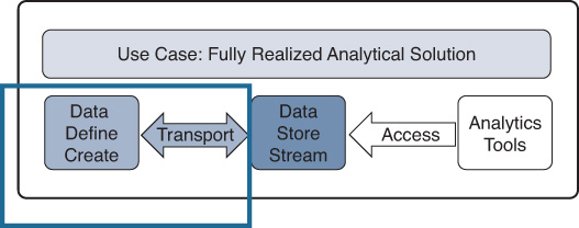
So how do all these overlays and underlays fit together in a data sense? In a networking environment, there are three major “planes” of activity. Recall from high school math class that a plane is not actually visible but is a layer that connects things that coexist in the same flat space. Here the term planes is used to indicate different levels of operation within a single physical, logical, or virtual entity described as a network. Each plane has its own transparency page to flip onto the diagram of the base network. We can summarize the major planes of operation based on three major functions and assign a data context to each. From a networking perspective, these are the three major planes (see Figure 3-2):
Management plane—This is the plane where you talk to the devices and manage the software, configuration, capabilities, and performance monitoring of the devices.
Control plane—This is the plane where network components talk to each other to set up the paths for data to flow over the network.
Data plane—This is the plane where applications use the network paths to share data.
These planes are important because they represent different levels and types of data coming from your infrastructure that you will use differently depending on the analytics solution you are developing. You can build analytics solutions using data from any one or more of these planes.
The management plane provides the access to any device on your network, and you use it to communicate with, configure, upgrade, monitor, and extract data from the device. Some of the data you extract is about the control plane, which enables communication through a set of static or dynamic configuration rules in network components. These rules allow networking components to operate as a network unit rather than as individual components. You can also use the management plane to get data about the things happening on the data plane, where data actually moves around the network (for example, the analytics application data that was previously called an overlay). The software overlay applications in your environment share the data plane. Every network component has these three planes, accessible directly to the device or through a centralized controller that commands many such devices, physical or virtual.
This planes concept is extremely important as you start to work with analytics and more virtualized network architectures and applications. If you already know it, feel free to just skim or skip this section. If you do not, a few analogies in the upcoming pages will aid in your understanding.
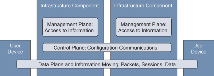
In this first example, look at the very simple network diagram shown in Figure 3-3, where two devices are communicating over a very simple routed network of two routers. In this case, you use the management plane to ask the routers about everything in the little deployment—all devices, the networks, the addressing, MAC addresses, IP addresses, and more. The routers have this information in their configuration files.
For the two user laptop devices to communicate, they must have connectivity set up for them. The routers on the little network communicate with each other, creating an instance of control plane traffic in order to set up the common network such that the two hosts are communicating with each other. The routers communicate with each other using a routing protocol to share any other networks that each knows about. A type of communication used to configure the devices to forward properly is control plane communication—communication between the participating network components to set up the environment for proper data forwarding operation.
I want to add a point of clarification. The routers have a configuration item that instructs them to run the routing protocol. You find this in the configuration you extract using the management plane, and it is a “feature” of the device. This particular feature creates the need to generate control plane traffic communications. The feature configuration is not in the control plane, but it tells you what you should see in terms of control plane activity from the device. Sometimes you associate feature information with the control plane because it is important context for what happens on the control plane communications channels.
The final area here is the data plane, which is the communications plane between the users of the little network. They could be running an analytics application or running Skype. As long as the control plane does its work, a path through the routers is available here for the hosts to talk together on a common data plane, enabling the application overlay instance between the two users to work. If you capture the contents of the Skype session from the data plane, you can examine the overlay application Skype in a vacuum. In most traditional networks, the control plane communication is happening across the same data plane paths (unless a special design dictates a completely separate path).
Next, let’s look at a second example that is a little more abstract. In this example, a pair of servers provides cloud functionality using OpenStack cloud virtualization, as shown in Figure 3-4. OpenStack is open source software used to build cloud environments on common servers, including virtualized networking components used by the common servers. Everything exists in software, but the planes concept still applies.
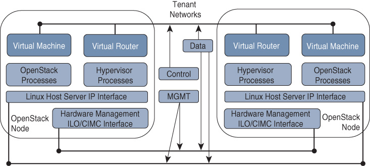
The management plane is easy, and hopefully you understand this one: The management plane is what you talk to, and it provides information about the other planes, as well as information about the network components (whether they are physical or virtual, server or router) and the features that are configured. Note that there are a couple of management plane connections here now: A Linux operating system connection was added, and you need to talk to the management plane of the server using that network.
In cloud environments, some interfaces perform both management and control plane communications, or there may be separate channels set up for everything. This area is very design specific. In network environments, the control plane communication often uses the data plane path, so that the protocols have actual knowledge of working paths and the experience of using those paths (for example, latency, performance). In this example, these concepts are applied to a server providing OpenStack cloud functionality. The control plane in this case now includes the Linux and OpenStack processes and functions that are required to set up and configure the data plane for forwarding. There could be a lot of control plane, at many layers, in cloud deployments.
A cloud control plane sets up data planes just as in a physical network, and then the data plane communication happens between the virtual hosts in the cloud. Note that this is shown in just a few nodes here, but these are abstracted planes, which means they could extend into hundreds or thousands of cloud hosts just like the ones shown.
When it comes to analytics, each of these planes of activity offers a different type of data for solving use cases. It is common to build solutions entirely from management plane data, as you will see in Chapter 10, “Developing Real Use Cases: The Power of Statistics,” and Chapter 11, “Developing Real Use Cases: Network Infrastructure Analytics.” Solutions built entirely from captured data plane traffic are also very popular, as you will see in Chapter 13, “Developing Real Use Cases: Data Plane Analytics.” You can use any combination of data from any plane to build solutions that are broader, or you can use focused data from a single plane to examine a specific area of interest.
Things can get more complex, though. Once the control plane sets things up properly, any number of things can happen on the data plane. In cloud and virtualization, a completely new instance of the control plane for some other, virtualized network environment may exist in the data plane. Consider the network and then the cloud example we just went through. Two virtual machines on a network communicate their private business over their own data plane communications. They encrypt their data plane communications. At first glance, this is simply data plane traffic between two hosts, which could be running a Skype session. But then, in the second example, those computers could be building a cloud and might have their own control plane and data plane inside what you see as just a data plane. If one of their customers is virtualizing those cloud resources into something else…. Yes, this rabbit hole can go very deep. Let’s look at another analogy here to explore this further.
Consider again that you and every one of your neighbors uses the same infrastructure of roads to come and go. Each of you has your own individual activities, and therefore your behavior on that shared road infrastructure represents your overlays—your “instances” using the infrastructure in separate ways. Your activities are data plane entities there, much like packets and applications riding your corporate networks, or the data from virtual machines in an OpenStack environment. In the roads context, the management plane is the city, county, or town officials that actually build, clean, clear, and repair the roads. Although it affects you at times (everybody loves road repair and construction), their activity is generally separate from yours, and what they care about for the infrastructure is different from your concerns.
The control plane in this example is the communications system of stoplights, stop signs, merge signs, and other components that determine the “rules” for how you use paths on the physical infrastructure. This is a case where the control plane has a dedicated channel that is not part of the data plane. As in the cloud tenant example, you may also have your own additional “family control plane” set of rules for how your cars use those roads (for example, 5 miles per hour under the speed limit), which is not related at all to the rules of the other cars on the roads. In this example, you telling your adolescent driver to slow down is control plane communication within your overlay.
Review of the Planes
Before going deeper, let’s review the three planes.
The management plane is the part of the infrastructure where you access all the components to learn information about the assets, components, environment, and some applications. This may include standard items such as power consumption, central processing units (CPUs), memory, or performance counters related to your environment. This is a critical plane of operation as it is the primary mechanism for configuring, monitoring, and getting data from the networking environment—even if the data is describing something on the control or data planes. In the sever context using OpenStack, this plane is a combination of a Hewlett-Packard iLO (Integrated Lights Out) or Cisco IMC (Integrated Management Controller) connection, as well as a second connection to the operating system of the device.
The control plane is the configuration activity plane. Control plane activities happen in the environment to ensure that you have working data movement across the infrastructure. The activities of the control plane instruct devices about how to forward traffic on the data plane (just as stoplights indicate how to use the roads). You use standard network protocols to configure the data plane forwarding. The communications traffic between these protocols is control plane traffic. Protocol examples are Open Shortest Path First (OSPF) and Border Gateway Protocol (BGP) and, at a lower level of the network, Spanning Tree Protocol (STP). Each of these common control plane protocols has both an operating environment and a configured state of features, both of which produce interesting data for analysis of IT environments. Management plane features (configuration items) are often associated with the control plane activities.
The data plane consists of actual traffic activity from node to node in an IT networking infrastructure. This is also a valuable data source as it represents the actual data movement in the environment. When looking at data plane traffic, there are often external sensors, appliances, network taps, or some “capture” mechanisms to evaluate the data and information movement. Behavioral analytics and other user-related analysis account for one “sub-plane” that looks at what the users are doing and how they are using the infrastructure. Returning to the traffic analysis analogy, by examining all traffic on the data plane by counting cars at an intersection, it may be determined that a new traffic control device is required at that intersection. Based on examining one sub-plane of traffic, it may be determined that the sub-plane needs some adjustment. Behavioral analysis on your sub-plane or overlay as a member of the all cars data plane may result in you getting a speeding ticket!
I recall first realizing that these planes exist. At first, they were not really a big deal to me because every device was a single entity and performed a single purpose (and I had to walk to work uphill both ways in the snow to work on these devices). But as I started to move into network and server virtualization environments, I realized the absolute necessity of understanding how these planes work because we could all be using the same infrastructure for entirely different purposes—just as my neighbors and I drive the same roads in our neighborhoods to get to work or stores or the airport. If you want to use analytics to find insights about virtualized solutions, you need to understand these planes. The next section goes even deeper and provides a different analogy to bring home the different data types that come from these planes of operation.
Data and the Planes of Operation
You now know about three levels of activity—the three planes of operation in a networking environment. Different people see data from various perspectives, depending on their backgrounds and their current context. If you are a sports fan, the data you see may be the statistics such as batting average or points scored. If you are from a business background, the data you see may be available in business intelligence (BI) or business analytics (BA) dashboards. If you are a network engineer, the data you see may be inventory, configuration, packet, or performance data about network devices, network applications, or users of your network.
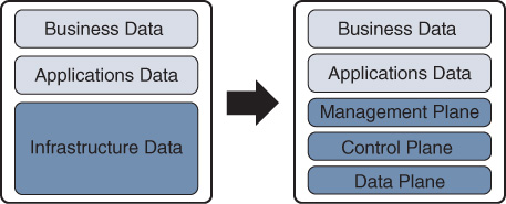
Data that comes from the business or applications reporting functions in your company is not part of these three planes, but it provides important context that you may use in analysis. Context is a powerful addition to any solution. Let’s return to our neighbor analogy: Think of you and your family as an application riding on the network. How much money you have in the bank is your “business” data. This has nothing to do with how you are using the infrastructure (for example, roads) or what your application might be (for example, driving to sports practice), but it is very important nonetheless as it has an impact on what you are driving and possible purposes for your being out there on the infrastructure. As more and more of the traditional BI/BA systems are modernized with machine learning, you can use business layer data to provide valuable context to your infrastructure-level analysis. At the time of this writing, net neutrality has been in the news. Using business metrics to prioritize applications on the Internet data plane by interacting directly with the control plane seems like it could become a reality in the near future. The important thing to note is that context data about the business and the applications is outside the foundational network data sources and the three planes (see Figure 3-5). The three planes all provide data about the infrastructure layer only.
When talking about business, applications, or network data, the term features is often used to distinguish between the actual traffic that is flowing on the network and things that are known about the application in the traffic streams. For example, “myApp version 1.0” is a feature about an application riding on the network. If you want to see how much traffic is actually flowing from a user to myApp, you need to analyze the network data plane. If you want to see the primary path for a user to get to myApp, you need to examine the control plane configuration rules. Then you can validate your configuration intent by asking questions of the management plane, and you can further validate that it is operating as instructed by examining the data plane activity with packet captures.
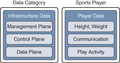
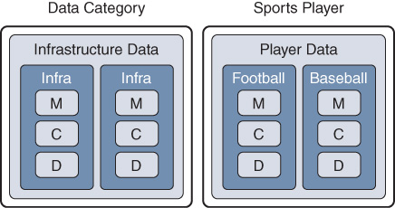
In an attempt to clarify this complex topic, let’s consider one final analogy related to sports. Say that the “network” is a sports league, and you know a player playing within it (much like a router, switch, or server sitting in an IT network). Management plane conversations are analogous to conversations with sports players to gain data. You learn a player’s name, height, weight, and years of experience. In fact, you can use his or her primary communication method (the management plane) to find out all kinds of features about the player. Combining this with the “driving on roads” infrastructure analogy, you use the management plane to ask the player where he or she is going. This can help you determine what application (such as going to practice) the player is using the roads infrastructure for today.
Note that you have not yet made any assessment of how good a player is, how good your network devices are, or how good the roads in your neighborhood look today. You are just collecting data about a sports player, an overlay application, or your network of roads. You are collecting features. The mappings in Figure 3-6 show how real-world activities of a sports player map to the planes.
The control plane in a network is like player communication with other players in sports to set up a play or an approach that the team will try. American football teams line up and run through certain plays against defensive alignments in order to find the optimal or best way to run a play. The same thing happens in soccer, basketball, hockey, and any other sport where there are defined plays. The control plane is the layer of communication used between the players to ensure that everybody knows his or her role in the upcoming activity. The control plane on a network, like players communicating during sports play, is always on and always working in reaction to current conditions.
That last distinction is very important for understanding the control plane of the network. Like athletes practicing plays so that they know what to do given a certain situation, network components share a set of instructions for how the network components should react to various conditions on the network. You may have heard of Spanning Tree Protocol, OSPF, or BGP, which are like plays where all the players agree on what happens at game time. They all have a “protocol” for dealing with certain types of situations. Your traffic goes across your network because some control plane protocol made a decision about the best way to get you from your source to your destination; more importantly, the protocol also set up the environment to make it happen. If we again go back to the example of you as a user of the network of roads in your neighborhood, the control plane is the system of instructions that happened between all of the stoplights to ensure orderly and fair sharing of the roads.
You will find that a mismatch between the control plane instruction and the data plane forwarding is one of the most frustrating and hard-to-find problems in IT networks. Just gaining an understanding that this type of problem exists will help you in your everyday troubleshooting. Imagine the frustration of a coach who has trained his sports players to run a particular play, but on game day, they do something different from what he taught them. That is like a control plane/data plane mismatch, which can be catastrophic in computer networks. When you have checked everything, and it all seems to be correct, look at the data plane to see if things are moving as instructed.
How do you know that the data plane is performing the functions the way you intended them to happen? For our athletes, the truth comes out on the dreaded film day with coach after the game. For your driving, cameras at intersections may provide the needed information. For networks, data plane analysis tells the story. Just as you know how a player performed, or just as you can see how you used an intersection while driving, you can determine how the data packets your network devices moved. Further, you can see many details about those packets. The data plane is where you get all the network statistics that everyone is familiar with. How much traffic is moving through the network? What applications are using the network? What users are using the network? Where is this traffic actually flowing on my network? Is this data flowing the way it was intended to flow when the environment was set up? Examine the data plane to find out.
Planes Data Examples
This section provides some examples of the data that you can see from the various planes. Table 3-1 shows common examples of management plane data.
Table 3-1 Management Plane Data Examples
Source |
Data |
What It Tells You |
Example |
Management plane command output |
Product family |
Broad category of device |
Cisco Nexus 5500 Series switches |
Management plane command output |
Product identification |
Exact device type |
N5K_C5548P |
Management plane command output |
Physical type |
Component type |
Chassis |
Management plane command output |
Software version |
Software version running on the component |
5.1(3)N2(1) |
Management plane configuration file |
Configured routing protocol 1 |
A configuration entry for a routing protocol |
Router OSPF x |
Management plane command output |
OSPF neighbors |
Number of current OSPF neighbors configured |
Neighbor x.x.x.x |
Management plane configuration file |
Configured routing protocol 2 |
A configuration entry for a routing protocol |
Router BGP xxxxx |
Management plane command output |
Number of CPU cores |
Data about the physical CPU configuration |
8 |
Management plane command output |
CPU utilization |
CPU utilization at some point in time |
30% |
Management plane command output |
Memory |
Amount of memory in the device |
16 GB |
Management plane command output |
Memory utilization |
Amount of memory consumed given the current processes at some point in time |
5 GB |
Management plane command output |
Interfaces |
Number of interfaces in the device |
50 |
Management plane command output |
Interface utilization |
Percentage of utilization of any given interface |
45% |
Management plane command output |
Interface packet counters |
Number of packets that have been forwarded by this interface since it was last cleared |
1,222,333 |
Observed value or ask the town |
Road surface |
From the road analogy, describes the road surface |
asphalt |
Asking the player |
Player weight |
From the sports player analogy, describes the player |
200 lb |
Asking the player |
Player 1 position 1 |
Describes the role of the player |
Running-back |
Asking the player |
Player 1 position 2 |
Describes another role of the player |
Signal caller |
In the last two rows of Table 3-1, note that the same player performs multiple functions: This player plays multiple positions on the same team. Similarly, single network devices perform multiple roles in a network and appear to be entirely different devices. A single cab driver can be part of many “going somewhere” instances. This also happens when you are using network device contexts. This is covered later in this chapter, in the section “A Wider Rabbit Hole.”
Notice that some of the management plane information (OSPF and packets) is about control plane and data plane information. This is still a “feature” because it is not communication (control plane) or actual packets (data plane) flowing through the device. This is simply state information at any given point in time or features you can use as context in your analysis. This is information about the device, the configuration, or the traffic.
The control plane, where the communication between devices occurs, sets up the forwarding in the environment. This differs from management plane traffic, as it is communication between two or more entities used to set up the data plane forwarding. In most cases, these packets do not use the dedicated management interfaces of the devices but instead traverse the same data plane as the application overlay instances. This is useful for gathering information about the path during the communication activity. Control plane protocols examine speed, hop counts, latency, and other useful information as they traverse the data plane environments from sender to receiver. Dynamic path selection algorithms use these data points for choosing best paths in networks. Table 3-2 provides some examples of data plane traffic that is control plane related.
Table 3-2 Control Plane Data Examples
Source |
Data |
What It Tells You |
Example |
Captured traffic from the data plane |
OSPF neighbor packets between two devices |
Control plane communication between these two devices for an instance of OSPF |
Router LSA (link-state advertisement) packets |
Captured traffic from the data plane |
BGP neighbor packets between two devices |
Control plane communication between these two devices for an instance of BGP |
BGP keepalives |
Captured traffic from the data plane |
Spanning-tree packets |
Communication between neighboring devices to set up Layer 2 environments |
Spanning-tree BPDUs (bridge protocol data units) |
Municipality activity logs |
Roads example stoplight system |
Communications between intersection stoplights to ensure that all lights are never green at same time |
Electronic communication that is not part of the data plane (the roads) but is part of the traffic system |
Listening to the communications during an ongoing play |
Sports player communication—football |
Communications between the players to set up the environment |
Play calls in a huddle or among players prior or during the play |
Listening to the communications during an ongoing play |
Same sports player communication—baseball |
Communications between the players to set up the environment |
Hand signals to fielders about what pitch is coming |
The last two items in Table 3-2 are interesting in that the same player plays two sports! Recall from the management plane examples in Table 3-1 that the same device can perform multiple roles in a network segmentation scenario, as a single node or as multiple nodes split into virtual contexts. This means that they could also be participating in multiple control planes, each of which may have different instructions for instances of data plane forwarding. A cab driver as part of many “going somewhere” instances has many separate and unrelated control plane communications throughout a typical day.
As you know, the control plane typically uses the same data plane paths as the data plane traffic. Network devices distinguish and prioritize known control plane protocols over other data plane traffic because correct path instruction is required for proper forwarding. Have you ever seen a situation in which one of the sports players in your favorite sport did not hear the play call? In such a case, the player does not know what is happening and does not know how to perform his or her role, and mistakes happen. The same type of thing can happen on a network, which is why networks prioritize these communications based on known packet types. Cisco also provides quality-of-service (QoS) mechanisms to allow this to be configurable for any custom “control plane protocols” you want to define that network devices do not already prioritize.
The data plane is the collection of overlay instance packets that move across the networks in your environment (including control plane communications). As discussed in Chapter 2, when you build an overlay analytics solution, all of the required components from your analytics infrastructure model comprise a single application instance within the data plane. When developing network analytics solutions, some of your data feeds from the left of the analytics infrastructure model may be reaching outside your application instance and back into the management plane of the same network. In addition, your solution may be receiving event data such as syslog data, as well as data and statistics about other applications running within the same data plane. For each of these applications, you need to gather data from some higher entity that has visibility into that application state or, more precisely, is communicating with the management plane of each of the applications to gather data about the application so that you can use that summary analysis in your solution. Table 3-3 provides some examples of data plane information.
Table 3-3 Data Plane Data Examples
Source |
Data |
What It Tells You |
Example |
Data plane packet capture |
Your analytics streaming data packets between a data source and your data storage |
Packets from a single application overlay instance |
Packets from a network source you have set up to the receiver you have set up, such as a Kafka bus |
Data plane packet capture |
Your email application |
Email packets, and email details inside the packets |
Packets from your email server to all users with email clients |
Data plane packet capture |
Your music streaming services |
A streaming music session outside the packets and where and what you are listening to inside the packets |
Pandora or Amazon music session packets between your listening device and the service location |
Data plane packet capture |
Your browser session |
Packets between you and the Internet for a single session (you may have several of these) |
A single session between you and www.cisco.com |
Data plane packet capture |
Routing protocol session between two router devices |
A data plane application overlay instance outside the packets (your control plane analysis is based on the data about and inside these packets) |
An OSPF routing communications session between two of your core routers |
Observing and recording the activity |
Sports player 1 activity |
Information about a single player performing the activity he/she has been instructed to do by the control plane communication |
Running, throwing, blocking |
Observing and recording the activity |
Sports player 2 activity |
Information about a second player performing the activity he/she has been instructed to do by the control plane communication |
Running, throwing, blocking |
Tracking your car along the path |
Roads analogy 1 |
Information about you and your family using the roads system to go to work |
Your car and driving activity on the various roads while going to work |
Tracking your car along the path |
Roads analogy 2 |
Information about you and your family using the roads system to go to the grocery store |
Your car and driving activity on the various roads while going to the store |
Data plane packet capture |
Management plane for a network overlay |
A session that uses your network data plane to reach inside an encapsulated network session |
A Virtual Extensible LAN (VXLAN)-encapsulated virtual network instance running over your environment |
Data plane packet capture |
Control plane for a network overlay |
A communications session between two network components, physical or virtual, that are tunneling through your networks |
A session between virtual routers running in servers and using VXLAN encapsulation as part of an entire network “instance” running in your data plane |
What are the last two items in Table 3-3? How are the management plane and somebody else’s control plane showing up on your data plane? As indicated in the management and control plane examples, a single, multitalented player can play multiple roles side by side, just as a network device can have multiple roles, or contexts, and a cab driver can move many different people in the same day.
If you drill down into a single overlay instance, each of these roles may contain data plane communications that include the management, control, and data planes of other, virtualized instances. If your player is also a coach and has players of his own, then for his coaching role, he has entire instances of new players. Perhaps you have a management plane to your servers that have virtual networking as an application. Virtual network components within this application all have control plane communications for your virtual networks to set up a virtual data plane. This all exists within your original data plane. If the whole thing exists in the cloud, these last two are you.
Welcome to cloud networking. Each physical network typically has one management and control plane at the root. You can segment this physical network to adjacent networks where you treat them separately. You can virtualize instances of more networks over the same physical infrastructure or segment.
Within each of these adjacent networks, at the data plane, it is possible that one or more of the data plane overlays is a complete network in itself. Have you ever heard of Amazon Web Services (AWS), Azure, NFV, or VPC (Virtual Packet Core)? Each of these has its own management, control, and data planes related to the physical infrastructure but support creation of full network instances inside the data plane, using various encapsulation or tunneling mechanisms. Each of these networks also has its own planes of operation. Adjacent roles is analogous to a wider rabbit hole, and more instances of networks within each of them is analogous to a deeper rabbit hole.
A Wider Rabbit Hole
Prior to that last section, you understood the planes of data that are available to you, right? Ten years ago, you could have said yes. Today, with segmentation, virtualization, and container technology being prevalent in the industry, the answer may still be no. The rabbit hole goes much wider and much deeper. Let’s first discuss the “wider” direction.
Consider your sports player again. Say that you have gone deep in understanding everything about him. You understand that he is a running back on a football team, and you know his height and weight. You trained him to run your special off-tackle plays again and again, based on some signal called out when the play starts (control plane). You have looked at films to find out how many times he has done it correctly (data plane). Excellent. You know all about your football player.
What if your athlete also plays baseball? What if your network devices are providing multiple independent networks? If you treat each of these separately, each will have its own set of management, control, and data planes. In sports, this is a multi-sport athlete. In networking, this is network virtualization. Using the same hardware and software to provide multiple, adjacent networks is like the same player playing multiple sports. Each of these has its own set of data, as shown Figure 3-7. You can also split physical network devices into contexts at the hardware level, which is a different concept. (We would be taking the analogy too far if we compared this to a sports player with multiple personalities.)
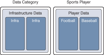
In this example showing the network split into adjacent networks (via contexts and/or virtualization), now you need to have an entirely different management conversation about each. Your player’s management plane data about position and training for baseball is entirely different from his position and training in football. The control plane communications for each are unique to each sport. Data such as height and weight are not going to change. Your devices still have a core amount of memory, CPU, and capacity. The things you are going to measure at the player’s data plane, such as his performance, need to be measured in very different ways (yards versus pitches or at bats). Welcome to the world of virtualization of the same resource—using one thing to perform many different functions, each of which has its own management, control, and data planes (see Figure 3-8).
This scenario can also be applied to device contexts for devices such as Cisco Nexus or ASA Firewall devices. Go a layer deeper: Virtualizing multiple independent networks within a device or context is called network virtualization. Alternatively, you can slice the same component into multiple “virtual” components or contexts, and each of these components has an instance of the three necessary planes for operation. From a data perspective, this also means you must gather data that is relative to each of these environments. From a solutions perspective, this means you need to know how to associate this data with the proper environment. You need to keep all data from each of the environments in mind as you examine individual environments. Conversely, you must be aware of the environment(s) supported by a single hardware device if you wish to aggregate them all for analysis of the underlying hardware.
Most network components in your future will have the ability to perform multiple functions, and therefore there will often be a root management plane and many sub-management planes. Information at the root may be your sports player’s name, age, height and weight, but there may be multiple management, control, and data planes per function for which your sports player or your network component performs. For each function, your sports player is part of a larger, spread-out network, such as a baseball team or a football team. Some older network devices do not support this; consider the roads analogy. It is nearly impossible to split up some roads for multiple purposes. Have you ever seen a parade that also has regular traffic using the same physical roads?
The ability to virtualize a component device into multiple other devices is common for cloud servers. For example, you might put software on a server that allows you to carve it into virtual machines or containers. You may have in your network Cisco Nexus switches that are deployed as contexts today. To a user, these contexts simply look like some device performing some services that are needed. As you just learned, you can use one physical device to provide multiple purposes, and each of these individual purposes has its own management, control, and data planes. Now recall the example from the data plane table (Table 3-3), where full management, control, and data planes exist within each of the data planes of these virtualized devices. The rabbit hole goes deeper, as discussed in the next section.
A Deeper Rabbit Hole
Have you ever seen the picture of a TV on a TV on a TV on a TV that appears to go on forever? Some networks seem to go to that type of depth.
You can create new environments entirely in software. The hardware management and control planes remain, but your new environment exists entirely within the data plane. This is the case with NFV and cloud networks, and it is also common in container, virtual machine, or microservices architectures. For a sports analogy to explain this, say that your athlete stopped playing and is now coaching sports. He still has all of his knowledge of both sports, as well as his own stats. Now he has multiple players playing for him, as shown in Figure 3-9, all of which he treats equally on his data plane activity of coaching.
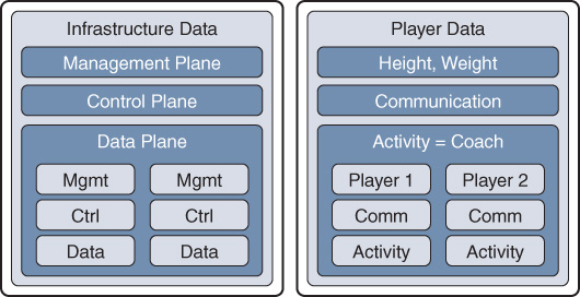
Each of these players has his or her own set of data, too. There is a management plane to find out about the players, a communications plane where they communicate with their teammates, and a data plane to examine the players’ activity and judge performance.
Figure 3-10 shows an example of an environment for NFV. You design virtual environments in these “pod” configurations such that you can add blocks of capacity as performance and scale requirements dictate. The NFV infrastructure exists entirely within the data plane of the physical environment because it exists within software, on servers on the right side of the diagram.
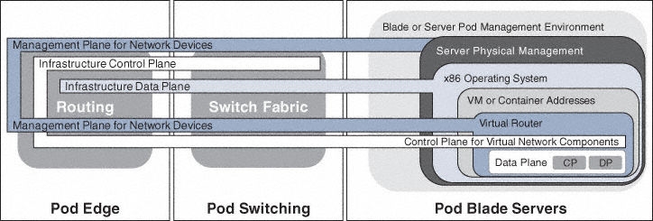
In order for the physical and virtual environments to function as a unit, you may need to extend the planes of operation. In this example, the pod is the coach, and each instance of an NFV function within the data plane environment is like another player on his team. Each team is a virtual network function)that may have multiple components or players. NFV supports many different virtual network functions at the same time, just as your coach can coach multiple teams at the same time. Although rare, each of these virtual network functions may also have an additional control plane and data plane within the virtual data planes shown in Figure 3-10. Unless the virtual network function is providing an isolated, secure function, you connect this very deep control and data plane to the hybrid infrastructure planes. This is one server. As you saw in the earlier OpenStack example, these planes could extend to hundreds or thousands of servers.
Summary
At this point, you should understand the layers of abstraction and the associated data. Why is it important to understand the distinction? With the sports player, you determine the size, height, weight, role, and build of your player at the management plane; however, this reveals nothing about what the player communicates during his role. You learn that by watching his control plane. You analyze what network devices communicate to each other by watching the control plane activity between the devices.
Now let’s move to the control plane. For your player, this is his current communication with his current team. If he is playing one sport, it is the on-field communications with his peers. However, if he is playing another sport as well, he has a completely separate instance that is a different set of control plane communications. Both sports have a data plane of the “activity” that may differ. You can virtualize network devices and entire networks into multiple instances—just like a multisport player and just as in the NFV example. Each of your application overlays could have a control plane, such as your analytics solution requesting traffic from a data warehouse.
If your player activity is “coaching,” he has multiple players who each has his own management, control, and data planes with which he needs to interact so they have a cohesive operation. If he is coaching multiple teams, the context of each of the management, control, and data planes may be different within each team, just as different virtual network functions in an NFV environment may perform different functions. Within each slice (team), this coach has multiple players, just as a network has multiple environments within each slice, each of which has its own management, control, and data planes. If your network is “hosting,” then the same concepts apply.
Chapter 4, “Accessing Data from Network Components,” discusses how to get data from network components. Now you know that you must ensure that your data analysis is context aware, deep down into the layers of segmentation and virtualization. Why do you care about these layers? Perhaps you have implemented something in the cloud, and you wish to analyze it. Your cloud provider is like the coach, and that provider has its own management, control, and data planes, which you will never see. You are simply one of the provider’s players on one of its teams (maybe team “Datacenter East”). You are an application running inside the data plane of the cloud provider, much like a Little League player for your sports coach. Your concern is your own management (about your virtual machines/containers), control (how they talk to each other), and data planes (what data you are moving among the virtual machines/containers). Now you can add context.