13
AIR‐SIDE ECONOMIZER TECHNOLOGIES
Nicholas H. Des Champs, Keith Dunnavant, and Mark Fisher
Munters Corporation, Buena Vista, Virginia, United States of America
13.1 INTRODUCTION
The development and use of computers for business and science was a result of attempts to remove the drudgery of many office functions and to speed the time required to do mathematically intensive scientific computations. As computers developed from the 1950s tube‐type mainframes, such as the IBM 705, through the minicomputers of the 70s and 80s, they were typically housed in a facility that was also home to many of the operation's top‐level employees. And, because of the cost of these early computers and the security surrounding them, they were housed in a secure area within the main facility. It was not uncommon to have them in an area enclosed in lots of glass so that the computers and peripheral hardware could be seen by visitors and employees. It was an asset that presented the operation as one that was at the leading edge of technology.
These early systems generated considerably more heat per instruction than today's servers. Also, the electronic equipment was more sensitive to temperature, moisture, and dust. As a result, the computer room was essentially treated as a modern‐day clean room. That is, high‐efficiency filtration, humidity control, and temperatures comparable to operating rooms were standard. Since the computer room was an integral part of the main facility and had numerous personnel operating the computers and the many varied pieces of peripheral equipment, maintaining the environment was considered by the facilities personnel as a more precise form of “air conditioning.”
Development of the single‐chip microprocessor during the mid‐1970s is considered to be the beginning of an era in which computers would be low enough in cost and had the power to perform office and scientific calculation, allowing individuals to have access to their own “personal” computers. The early processors and their host computers produced very little heat and were usually scattered throughout a department. For instance, an 8086 processor (refer to Table 13.1) generated less than 2 W of heat, and its host computer generated on the order of 25 W of heat (without monitor). Today's servers can generate up to 500 W of heat or more and when used in modern data centers (DCs) are loaded into a rack and can result in very high densities of heat in a very small footprint. Consider a DC with 200 racks at a density of 20,000 W/rack that results in 4 MW of heat to dissipate in a very small space.
TABLE 13.1 Chronology of computing processors
Source: Intel Corporation.
| Processor | Clock speed | Introduction | Mfg. process | Transistors |
|---|---|---|---|---|
| 4004 | 108 KHz | November 1971 | 10 μm | 2,300 |
| 8086 | 10 MHz | June 1978 | 3 μm | 29,000 1.87 W (sustained) |
| 386 | 33 MHz | June 1988 | 1.5 μm | 275,000 |
| 486 | 33 MHz | November 1992 | 0.8 μm | 1.4 million |
| Pentium | 66 MHz | March 1993 | 0.8 μm | 3.1 million |
| Pentium II | 233 MHz | May 1997 | 0.35 μm | 7.5 million |
| Pentium III | 900 MHz | March 2001 | 0.18 μm | 28 million |
| Celeron | 2.66 GHz | April 2008 | 65 nm | 105 million |
| Xeon MP X7460 | 2.66 GHz | September 2008 | 45 nm | 1.90 billion 170.25 W (sustained) |
Of course, there would be no demand for combining thousands of servers in large DCs had it not been for the development of the Internet and launching of the World Wide Web (WWW) in 1991 (at the beginning of 1993 only 50 servers were known to exist on the WWW), development of sophisticated routers, and many other ancillary hardware and software products. During the 1990s, use of the Internet and personal computers mushroomed as is illustrated by the rapid growth in routers: in 1991 Cisco had 251 employees and $70 million in sales, and by 1997 it had 11,000 employees and $7 billion in sales. Another example of this growth is shown by the increasing demand for server capacity: in 2011 there were 300 million new websites created, bringing the total to 555 million by the end of that year. The total number of Internet servers worldwide is estimated to be greater than 75 million.
As technology has evolved during the last several decades, so have the cooling requirements. No longer is a new DC “air‐conditioned,” but instead it is considered “process cooling” where air is delivered to a cold aisle, absorbs heat as it traverses the process, is sent to a hot aisle, and then is either discarded to ambient or returned to dedicated machines for extraction of the process heat and then sent back to the cold aisle. Today's allowable cooling temperatures reflect the conceptual change from air conditioning (AC) to process cooling. There have been four changes in ASHRAE's cooling guidelines [1] during the last nine years. In 2004, ASHRAE recommended Class 1 temperature was 68–77°F (20–25°C); in 2008 it was 64.4–80.6°F (18–27°C). In 2012, the guidelines remained the same in terms of recommended range but greatly expand the allowable range of temperatures and humidity in order to give operators more flexibility in doing compressor‐less cooling (using ambient air directly or indirectly) to remove the heat from the DC with the goal of increasing the DC cooling efficiency and reducing the energy efficiency metric, power usage effectiveness (PUE). Today, the 2015 guidelines further expanded the recommended range to a lower humidity level, reducing the amount of humidification needed to stay within the range.
13.2 USING PROPERTIES OF AMBIENT AIR TO COOL A DATA CENTER
In some instances it is the ambient conditions that are the principal criteria that determine the future location of a DC, but most often the location is based on acceptance by the community, access to networks, and adequate supply and cost of utilities in addition to being near the market it serves. Ambient conditions have become a more important factor as a result of an increase in allowable cooling temperature for the information technology (IT) equipment. The cooler, and sometimes drier, the climate, the greater period of time a DC can be cooled by using ambient air. For instance, in Reno, NV, air can be supplied all year at 72°F (22°C) with no mechanical refrigeration by using evaporative cooling techniques.
Major considerations by the design engineers when selecting the cooling system for a specific site are:
- Cold aisle temperature and maximum temperature rise across server rack
- Critical nature of continuous operation for individual servers and peripheral equipment
- Availability of sufficient usable water for use with evaporative cooling
- Ambient design conditions, i.e., yearly typical design as well as extremes of dry‐bulb (db) and wet‐bulb (wb) temperature
- Site air quality, i.e., particulate and gases
- Utility costs
Other factors are projections of initial capital cost, full‐year cooling cost, reliability, complexity of control, maintenance cost, and the effectiveness of the system in maintaining the desired space temperature, humidity, and air quality during normal operation and during a power or water supply failure.
Going forward, the two air‐side economizer cooling approaches, direct and indirect, are discussed in greater detail. A direct air‐side economizer (DASE) takes outdoor air (OA), filters and conditions it, and delivers it directly to the space. An indirect air‐side economizer (IASE) uses ambient air to indirectly cool the recirculating airstream without delivering ambient air to the space. Typically a DASE system will include a direct evaporative cooler (DEC) cooling system for cooling; ambient air traverses the wetted media, lowering the db temperature, and is controlled to limit the amount of moisture added to keep the space within the desired RH%. An IASE system typically uses some form of air‐to‐air heat exchanger (AHX) that does not transfer latent energy between airstreams. Typically, plate‐type, tubular, thermosiphon, or heat pipe heat exchangers are used. Please refer to Ref. [2] for information on AHXs.
13.3 ECONOMIZER THERMODYNAMIC PROCESS AND SCHEMATIC OF EQUIPMENT LAYOUT
13.3.1 Direct Air‐Side Economizer (DASE)
13.3.1.1 Cooling with Ambient Dry‐Bulb Temperature
The simplest form of an air‐side economizer uses ambient air directly supplied to the space to remove heat generated by IT equipment. Figure 13.1 shows a schematic of a typical DASE arrangement that includes a DEC, item 1, and a cooling coil, item 2. Without item 1 this schematic would represent a DASE that uses the db temperature of the ambient air to cool the DC. For this case, ambient air can be used to perform all the cooling when its temperature is below the design cold aisle temperature and a portion of the cooling when it is below the design hot aisle temperature. When ambient temperature is above hot aisle temperature, or ambient dew point (dp) exceeds the maximum allowed by the design, then the system must resort to full recirculation and all mechanical cooling. When ambient temperature is below the design cold aisle temperature, some of the heated process air is returned to the inlet plenum to mix with the incoming OA to yield the desired delivery temperature. In almost all cases, except in extreme cold climates, some level of mechanical cooling is required to meet the space cooling requirements, and, in most cases, the mechanical supplement will be designed to handle the full cooling load. The result is that for most regions of the world, the full‐year energy reduction is appreciable, but the capital equipment cost reflects the cost of having considerable mechanical refrigeration on board. Other factors to consider are costs associated with bringing high levels of OA into the building that result in higher rate of filter changes and less control of space humidity. Also, possible gaseous contaminants, not captured by standard high‐efficiency filters, could pose a problem.

FIGURE 13.1 Schematic of a typical direct air‐side economizer.
13.3.1.2 Cooling with Ambient Wet‐Bulb Temperature
If a source of usable water is available at the site, then an economical approach to extend the annual hours of economizer cooling, as discussed in the previous paragraph, is to add a DEC, item 1, as shown in Figure 13.1. The evaporative pads in a DEC typically can achieve 90–95% efficiency in cooling the ambient air to approach wb temperature from db temperature, resulting in a db temperature being delivered to space at only a few degrees above the ambient wb temperature. The result is that the amount of trim mechanical cooling required is considerably reduced from using ambient db and in many cases may be eliminated completely. In addition, there is greater space humidity control by using the DEC to add water to the air during colder ambient conditions. The relative humidity within the space, during cooler periods, is controlled with the face and bypass dampers on the DEC. It is important that the system is designed to prevent freeze conditions at the DEC or condensate formation in supply ductwork or outlet areas. There would be no humidity control however during the warmer ambient conditions. In fact, lack of humidity control is the single biggest drawback in using DASE with DEC. As with the db cooling, factors to consider are costs associated with bringing high levels of OA into the building, which results in higher rates of filter changes and less control of space humidity. Also, possible gaseous contaminants, not captured by standard high‐efficiency filters, could pose a problem. Even with these operating issues, the DASE using DEC is arguably the most efficient and least costly of the many techniques for removing waste heat from DCs, except for DASE used on facilities in extreme climates where the maximum ambient db temperature never exceeds the specified maximum cold aisle temperature.
A DASE with DEC cooling process is illustrated in Figure 13.2. In this instance, the cold aisle temperature is 75°F, and the hot aisle is 95°F, which is a fairly typical 20°F temperature difference, or Delta T (ΔT) across the IT equipment. With an ambient design wb of 67.7°F and a 90% effective evaporative process, the supply air (SA) to the space can be cooled to 70°F from 91.2°F, which is lower than specified. Under this type of condition, there are several control schemes that are used to satisfy the space cooling requirements:
- Reduce the process air flow to maintain the hot aisle temperature at 95°F, which increases the ΔT between the hot and cold aisles. Decreasing the process airflow results in considerably less fan power. This scheme is shown as the process between the two square end marks.
- Maintain the specified 20°F ΔT by holding the process airflow at the design value, which results in a lower hot aisle temperature. This is shown in the horizontal process line starting from “Out of DEC” but only increasing up to 90°F db return temperature.
- Use face and bypass dampers on the DEC to control the cold aisle SA temperature to 75°F as shown in the process between the two triangular end marks.
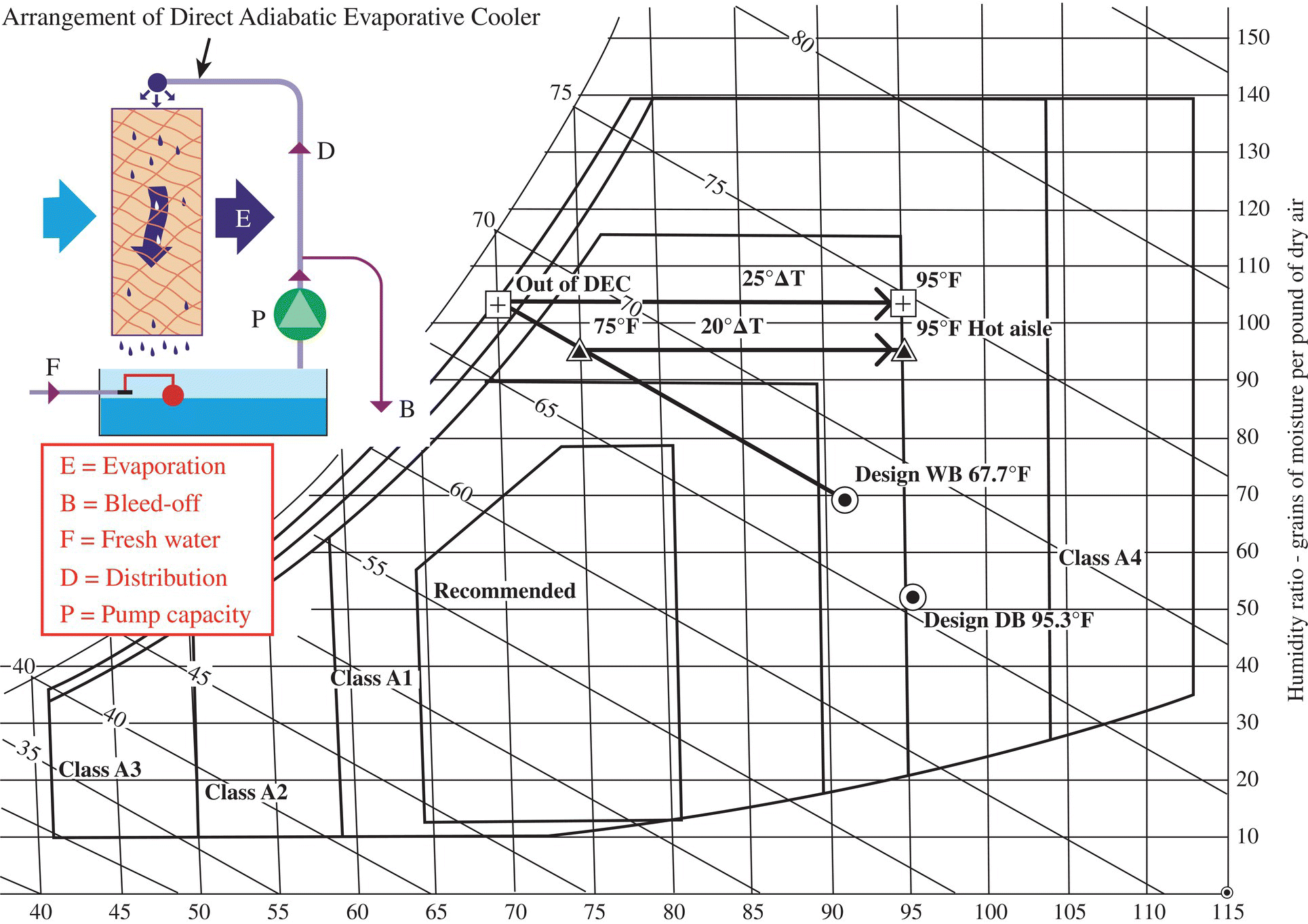
FIGURE 13.2 Direct cooling processes shown with ASHRAE recommended and allowable envelopes for DC supply temperature and moisture levels.
13.3.1.3 Arrangement of Direct Adiabatic Evaporative Cooler
A bank of multiple DASE with DEC units arranged in parallel is shown in Figure 13.3. Each of these units supplies 40,000 cubic feet per minute (CFM) of adiabatically cooled OA during warm periods and a blend of OA and recirculated air, as illustrated in Figure 13.1, during colder periods. The cooling air is supplied directly to the cold aisle, travels through the servers and other IT equipment, and is then directed to the relief dampers on the roof. Also shown in Figure 13.3 is a commonly used type of rigid, fluted direct evaporative cooling media.

FIGURE 13.3 At left: cooling system using bank of DASE with DEC units at the end wall of a DC; at right: the array of evaporative cooling media.
Source: Courtesy of Munters Corporation.
13.3.2 Indirect Air‐Side Economizer (IASE)
13.3.2.1 Air‐to‐Air Heat Exchangers
In many Datacom cooling applications, it is desirable to indirectly cool recirculated DC room air as opposed to delivering ambient OA directly into the space for cooling. This indirect technique allows for much more stable humidity control and significantly reduces the potential of airborne contaminants entering the space compared to DASE designs. When cooling recirculated air, dedicated makeup air units are added to the total cooling system to control space humidity and building pressure. An AHX serves as the intermediary that permits the use of ambient OA to cool the space without actually bringing the ambient OA into the space. The most commonly used types of AHX used for this purpose are plate and heat pipe as shown in Figure 13.4. Sensible wheel heat exchangers have also been used in IASE systems, but are no longer recommended due to concerns with air leakage, contaminant and/or humidity carryover, and higher air filtration requirements when compared with passive plate or heat pipe heat exchangers. Please refer to Ref. [2], Chapter 26, Air‐To‐Air Energy Recovery Equipment, for further information regarding performance and descriptions of AHX. Figure 13.5 illustrates the manner in which the AHX is used to transfer the heat from the hot aisle return air (RA) to the cooling air, com monly referred to as scavenger air (ScA) since it is discarded to ambient after it performs its intended purpose, that of absorbing heat. The effectiveness of an AHX, when taking into consideration the cost, size, and pressure drop, is usually selected to be between 65 and 75% when operating at equal airflows for the ScA and recirculating air.

FIGURE 13.4 Plate‐type (left) and heat pipe (right) heat exchangers.
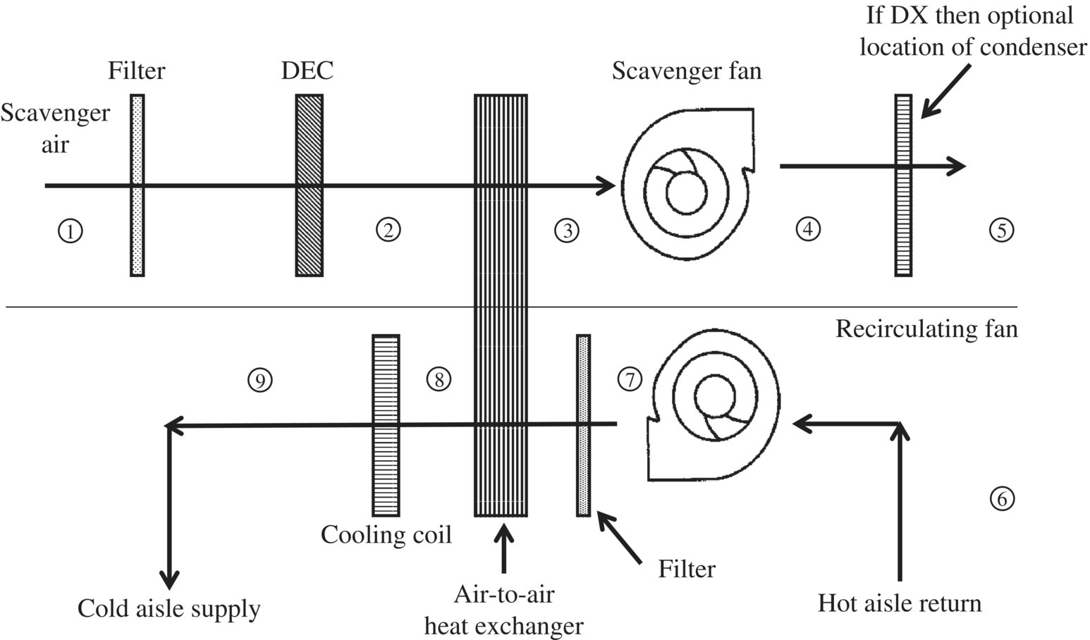
FIGURE 13.5 Schematic of typical indirect air‐side economizer.
Referring to the schematic shown in Figure 13.5, the ScA enters the system through a roughing filter at ① that removes materials that are contained in the OA that might hamper the operation of the components located in the scavenger airstream. If a sufficient amount of acceptable water is available at the site, then cooling the ScA with a DEC before it enters the AHX at ② should definitely be considered. Evaporatively cooling the ScA will not only extend the energy‐saving capability of the IASE over a greater period of time, but it will and also reduce the amount of mechanical refrigeration required at the extreme ambient design conditions. The ambient conditions used for design of cooling equipment are generally extreme db temperature if just an AHX is used and extreme wb temperature if a form of evaporative cooling is used to precool the ScA before it enters the heat exchanger. Extreme ambient conditions are job dependent and are usually selected using either Typical Meteorological Year 3 (TMY3) data, the extreme ASHRAE data, or even the 0.4% ASHRAE annual design conditions.
When DEC is used as shown in Figure 13.5, and trim direct expansion refrigeration (DX) cooling is required, then it is advantageous to place the condenser coil in the leaving scavenger airstream since its db temperature, in almost all cases, is lower than the ambient db temperature. If no DEC is used, then there could be conditions where the ScA temperature is above the RA. Under these circumstances, there should be a means to prevent the AHX from transferring heat in the wrong direction; otherwise heat will be transferred from the ScA to the recirculating air, and the trim mechanical refrigeration will not be able to cool the recirculating air to the specified cold aisle temperature. Vertical heat pipe AHXs automatically prevent heat transfer at these extreme conditions because if the ambient OA is hotter than the RA, then no condensing of the heat pipe working fluid will occur (process ② to ③ as shown in Fig. 13.5), and therefore no liquid will be returned to the portion of the heat pipe in the recirculating airstream (process ⑦ to ⑧). With the plate heat exchanger, a face and bypass section to direct ScA around the AHX may be necessary in order to prevent heat transfer, or else the condenser will need to be in a separate section, which would allow the scavenger fans to be turned off.
As an example, when using just an AHX without DEC and assuming an effectiveness of 72.5% (again using 75°F cold aisle and 95°F hot aisle), the economizer can do all of the cooling when the ambient db temperature is below 67.4°F. At lower ambient temperatures the scavenger fans are slowed in order to remove the correct amount of heat and save on scavenger fan energy. Above 67.4°F ambient the mechanical cooling system is staged on until at an ambient of 95°F or higher the entire cooling load is borne by the mechanical cooling system.
When precooling ScA with a DEC, it is necessary to discuss the cooling performance with the aid of a psychrometric chart. The numbered points on Figure 13.6 correspond to the numbered locations shown in Figure 13.5. On a design wb day ① of 92°F db/67.7°F wb, the DEC lowers the ScA db temperature from 92 to 70.1°F ②. The ScA then enters the heat exchanger and heats to 88.2°F ③. During this process, air returning from the hot aisle ⑥ is cooled from 95°F (no fan heat added) to 77.2°F ⑧, or 89% of the required cooling load. Therefore, on a design day using DEC and an AHX, the amount of trim mechanical cooling required ⑨ in Figure 13.5 is only 11% of the full cooling load, and the trim would only be called into operation for a short period of time during the year.
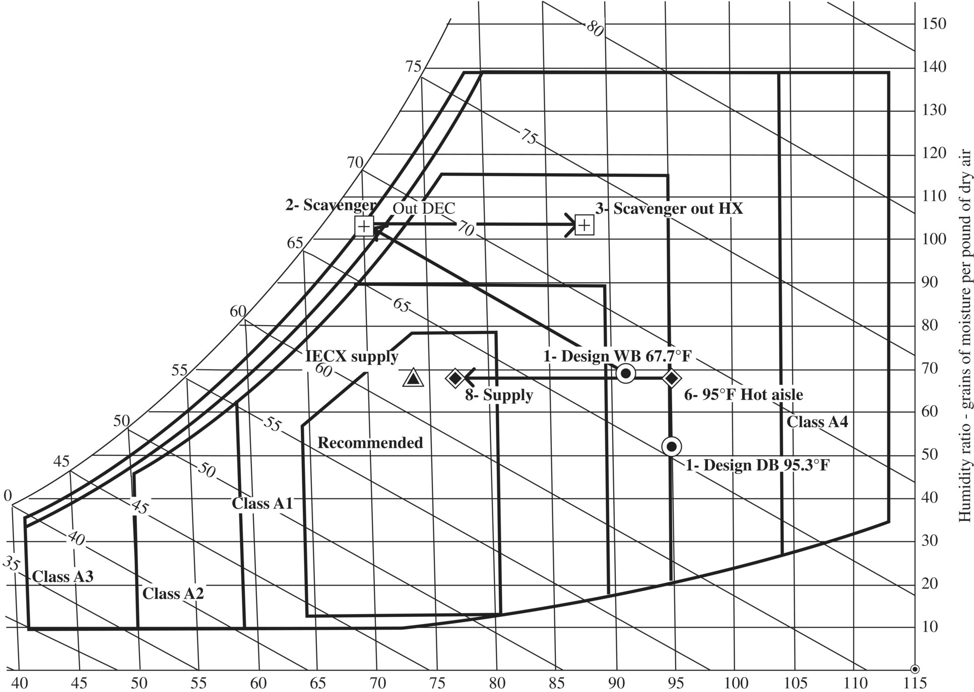
FIGURE 13.6 Psychrometric chart showing performance of IASE system with DEC precooling scavenger airstream.
13.3.2.2 Integral Air‐to‐Air Heat Exchanger/Indirect Evaporative Cooler
The previous section used a separate DEC and AHX to perform an indirect evaporative cooling (IEC) process. The two processes can be integrated into a single piece of equipment, known as an indirect evaporative cooling heat exchanger (IECX). The IECX approach, which uses wb temperature as the driving potential to cool Datacom facilities, can be more efficient than using a combination of DEC and AHX since the evaporative cooling process occurs in the same area as the heat removal process. It is important to note that with this process the evaporative cooling effect is achieved indirectly, meaning no moisture is introduced into the process airstream.
Configuration of a typical IECX is illustrated in Figure 13.7. The recirculating Datacom air returns from the hot aisle at, for example, 95°F and enters the horizontal tubes from the right side and travels through the inside of the tubes where it cools to 75°F. The recirculating air cools as a result of the indirect cooling effect of ScA evaporating water that is flowing downward over the outside of the tubes. Because of the evaporative cooling effect, the water flowing over the tubes and the tubes themselves approach ambient wb temperature. Typically, an IECX is designed to have wb depression efficiency (WBDE) in the range of 70–80% at peak ambient wb conditions. Referring to Figure 13.6, with all conditions remaining the same as the example with the dry AHX with a DEC precooler on the ScA, a 78% efficient IECX process is shown to deliver a cold aisle temperature of 73.7°F, shown on the chart as a triangle, which is below the required 75°F. Under these conditions the ScA fan speed is reduced to maintain the specified cold aisle temperature at 75 instead of 73.7°F.

FIGURE 13.7 Indirect evaporative cooled heat exchanger (IECX).
Source: Courtesy of Munters Corporation.
A unit schematic and operating conditions for a typical IECX unit design are shown in Figure 13.8. Referring to the airflow pattern in the schematic, air at 96°F comes back to the unit from the hot aisle ①, heats to 98.2°F through the fan ②, and enters the tubes of the IECX where it cools to 83.2°F ③ on a design ambient day of 109°F/75°F (db/wb). The trim DX then cools the supply to the specified cold aisle temperature of 76°F. At these extreme operating conditions, the IECX removes 67% of the heat load, and the DX removes the remaining 33% of the heat. This design condition will be a rare occurrence, but the mechanical trim cooling is sized to handle this extreme. For a facility in Quincy, WA, operating with these design parameters, the IEC economizer is predicted to remove 99.2% of the total annual heat load.
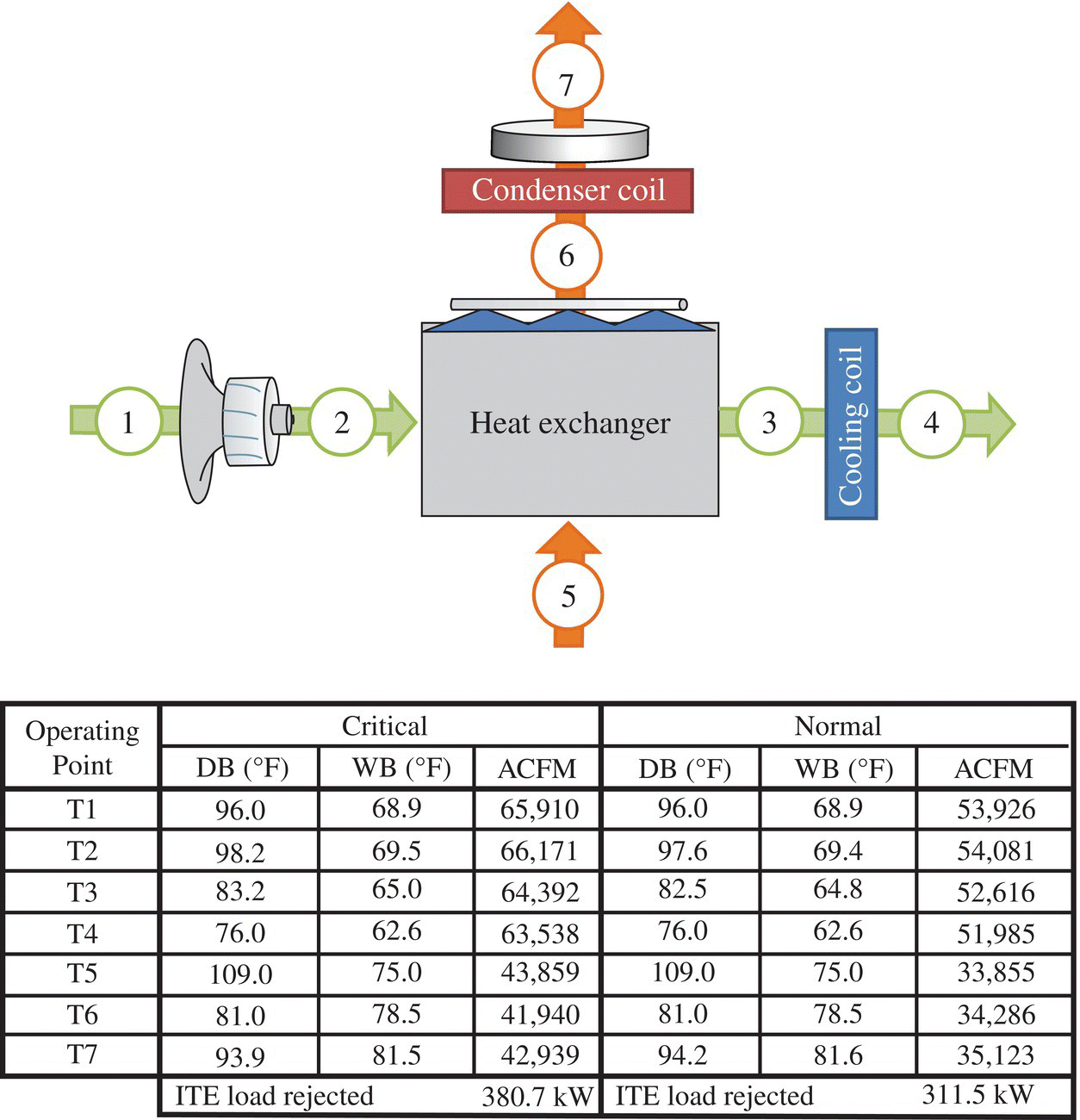
FIGURE 13.8 Schematic of a typical DC cooling IECX unit.
Source: Courtesy of Munters Corporation.
The period of time during the year that an economizer is performing the cooling function is extremely important because a Datacom facility utilizing economizer cooling has a lower PUE than a facility with conventional cooling using chillers and computer room air handler (CRAH) units or computer room air conditioner (CRAC) units. PUE is a metric used to determine the energy efficiency of a Datacom facility. PUE is determined by dividing the amount of power entering a DC by the power used to run the computer infrastructure within it. PUE is therefore expressed as a ratio, with overall efficiency improving as the quotient decreases toward 1. There is no firm consensus of the average PUE; from a survey of over 500 DCs conducted by the Uptime Institute in 2011 the average PUE was reported to be 1.8, but in 2012 the CTO of Digital Realty indicated that the average PUE for a DC was 2.5. Economizer PUE values typically range from as low as 1.07 for a DASE using DEC to a high of about 1.3, while IECX systems range from 1.1 to 1.2 depending upon the efficiency of the IECX and the site location. For example, if the economizer at a given location reduced the time that the mechanical refrigeration was operating by 99.7% during a year, then the cooling costs would be reduced by a factor of around 5 relative to a DC with the same server load operating at a PUE of 2.0.
Typically, in a DC facility where hot aisle containment is in place, the IECX system is able to provide cooling benefit even during the most extreme ambient design conditions. As a result, the mechanical refrigeration system, if it is required at all, is in most cases able to be sized significantly smaller than the full cooling load. This smaller amount of refrigeration is referred to as “trim DX,” since it only has to remove a portion of the total heat load. A further benefit of the IECX system is that, referring again to Figure 13.8, the ScA leaving the IECX ⑥ is brought close to saturation (and thus cooler than the ambient temperature) before performing its second job, that of removing heat from the refrigeration condenser coil. This cooler temperature entering the condenser coil improves compressor performance with the resulting lower condensing temperature.
Figure 13.9 shows a graph of operating power vs. ambient wb condition for a typical IECX unit, and the shaded area represents the number of hours in a typical year that each condition occurs in a given location, providing a set of bin hours (right ordinate) at which the IECX might operate at each wet bulb. Most of the hours are between about 11 and 75°F. The upper curve, medium dashed line, is the total operating power of the economizer cooling system. The short‐dashed curve is the DX power and the dot‐dash curve is the scavenger fan motor, both of which operate at full capacity at the extreme wb temperatures. The average weighted total power for the year is 117 kW. Typically, the lights and other electrical within the DC are about 3% of the IT load, so the total average load into the facility is 1500 kW × 1.03 + 117 kW or 1662 kW. This yields an average value of PUE of 1662/1500 or 1.108, an impressive value when compared with conventional cooling PUEs of 1.8–2.5. For this example, the onboard trim DX represented 24% of the 452.9 tons of heat rejection, which results in a lower connected load to be backed up with generators, as long as short‐term water storage is provided.
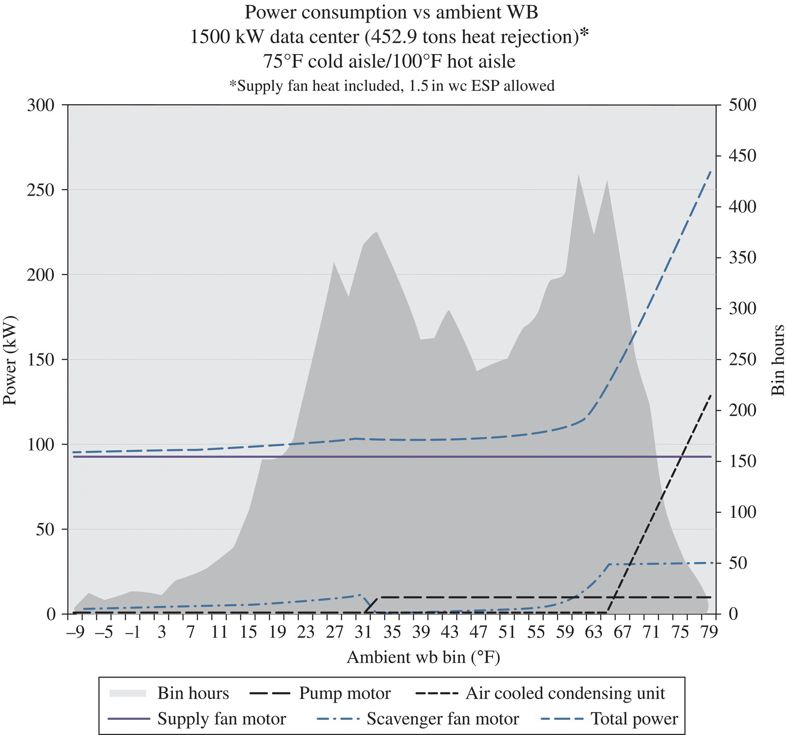
FIGURE 13.9 Power consumption for a typical IECX IASE cooling unit.
Source: Courtesy of Munters Corporation.
One company that has experienced great success implementing IECX systems is colocation provider Sabey Data Centers Inc. Figure 13.10 illustrates an aerial view of one of several Sabey DC facilities at their Intergate campus located in Quincy, WA. This campus has one of the largest IECX installations in the Western United States with a reported annual PUE of 1.13. Overall, the annual PUE of the campus is less than 1.2, which is impressive considering that these colocation facilities have variable loads and are often operating at partial loads below the design capacity (and higher efficiency points) of the equipment.
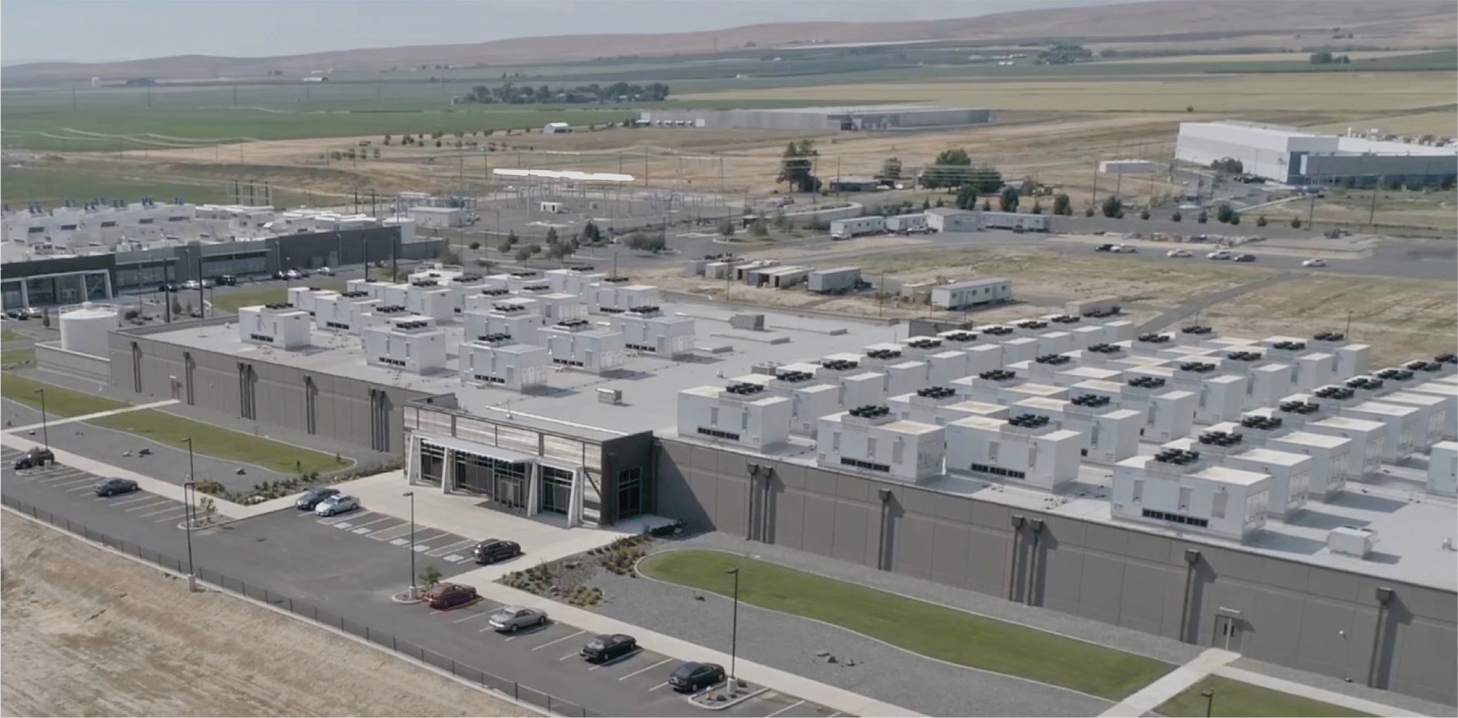
FIGURE 13.10 Aerial view of (42) indirect air‐side economizers (IASEs).
Source: Courtesy of Munters Corporation.
In order to give even a better understanding of how the IECX performs at different climatic conditions and altitudes, Figure 13.11 shows the percentage of cooling ton‐hours performed during the year: first the IECX operating wet (warm conditions using wb temperature), then second the IECX operating dry (cool conditions using db temperature), and third at extreme conditions the operation of DX. Fifteen cities are listed with elevations ranging from sea level to over 5,000 ft. The embedded chart gives a graphical representation of the energy saved during each operating mode. The last column is the percentage of time during the year that there are no compressors staged on and the IECX is handling the entire cooling load.
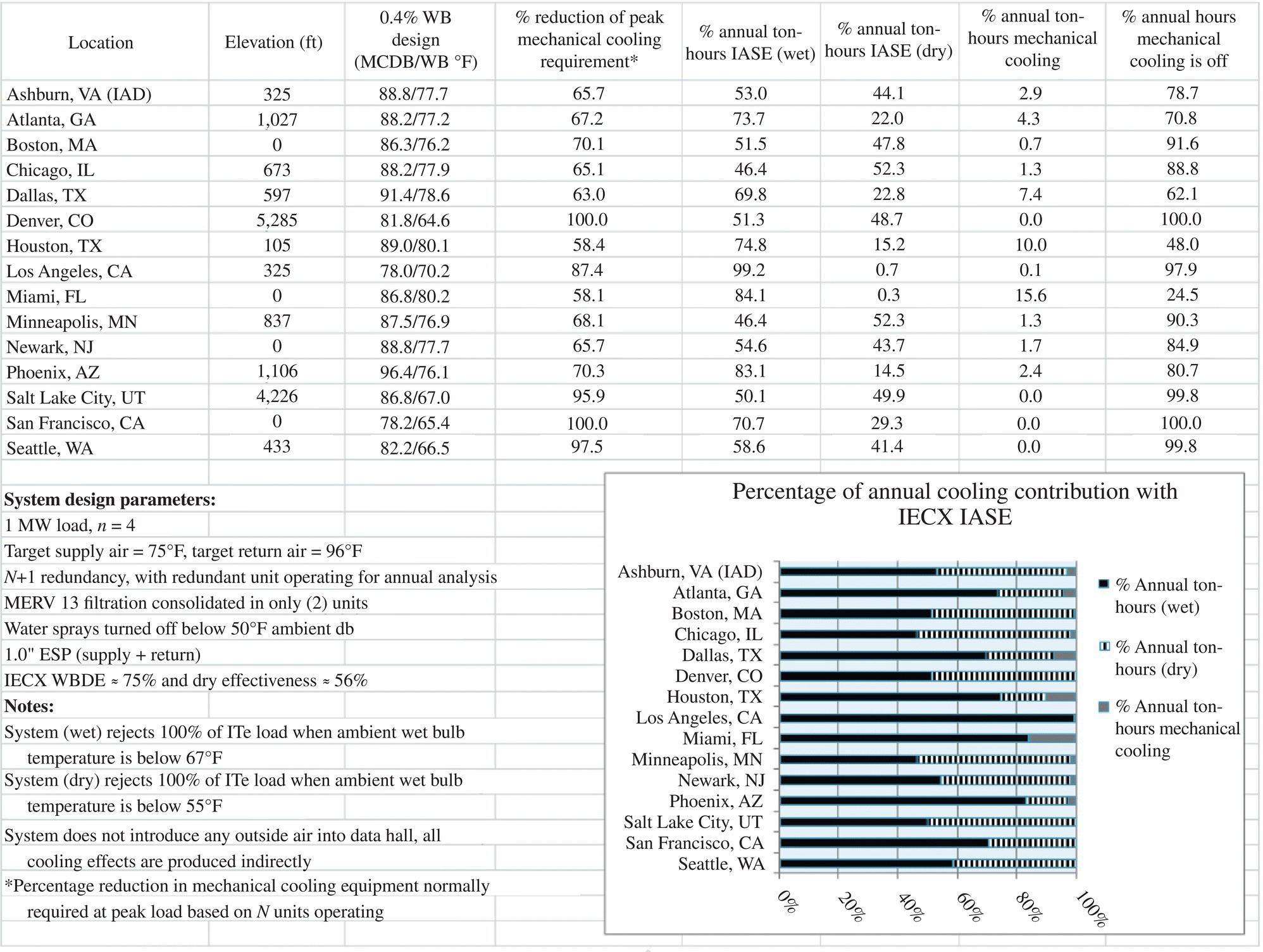
FIGURE 13.11 Analysis summary for modular DC cooling solution using IECX.
13.3.2.3 Trim Cooling Drain Trap Considerations
When using an indirect economizer in combination with a cooling coil used for trim cooling, there will be extended periods of time when mechanical cooling is not active. This can lead to “dry‐out” of the condensate traps, resulting in air leakage in or out of the recirculating air handler. This situation can impact pressurization control within the DC, and can also increase the amount of conditioned make‐up air required. It is recommended that the cooling coil drain traps be designed to prevent dry‐out and the resulting airflow within the condensate drain line, such as use of an Air‐Trap (which uses the fan pressure to trap air) instead of a P‐Trap (which uses water to trap air).
13.3.2.4 Other Indirect Economizer Types
There are other types of indirect economizers that can be considered based on the design of the DC facility and cooling systems. These are indirect water‐side economizer (IWSE) and indirect refrigerant‐side economizer (IRSE), and the primary difference between these and the IASEs discussed in this chapter is the working fluid from which the economizer is removing the heat energy. Where heat energy is being transported with water or glycol, an IWSE can be implemented. Similarly, in systems where a refrigerant is used to transport heat energy, an IRSE can be implemented. Either of these economizer types can be implemented with or without evaporative cooling, in much the same way an IASE can be, and similarly the overall efficiency of these economizer types depends on the efficiency of the heat exchange devices, efficiency of other system components, and facility location.
13.4 COMPARATIVE POTENTIAL ENERGY SAVINGS AND REQUIRED TRIM MECHANICAL REFRIGERATION
Numerous factors have an influence on the selection and design of a DC cooling system. Location, water availability, allowable cold aisle temperature, and extreme design conditions are four of the major factors. Figure 13.12 shows a comparison of the cooling concepts previously discussed as they relate to percentage of cooling load during the year that the economizer is capable of removing and the capacity of trim mechanical cooling that has to be on board to supplement the economizer on hot and/or humid days, the former representing full‐year energy savings and the latter initial capital cost.
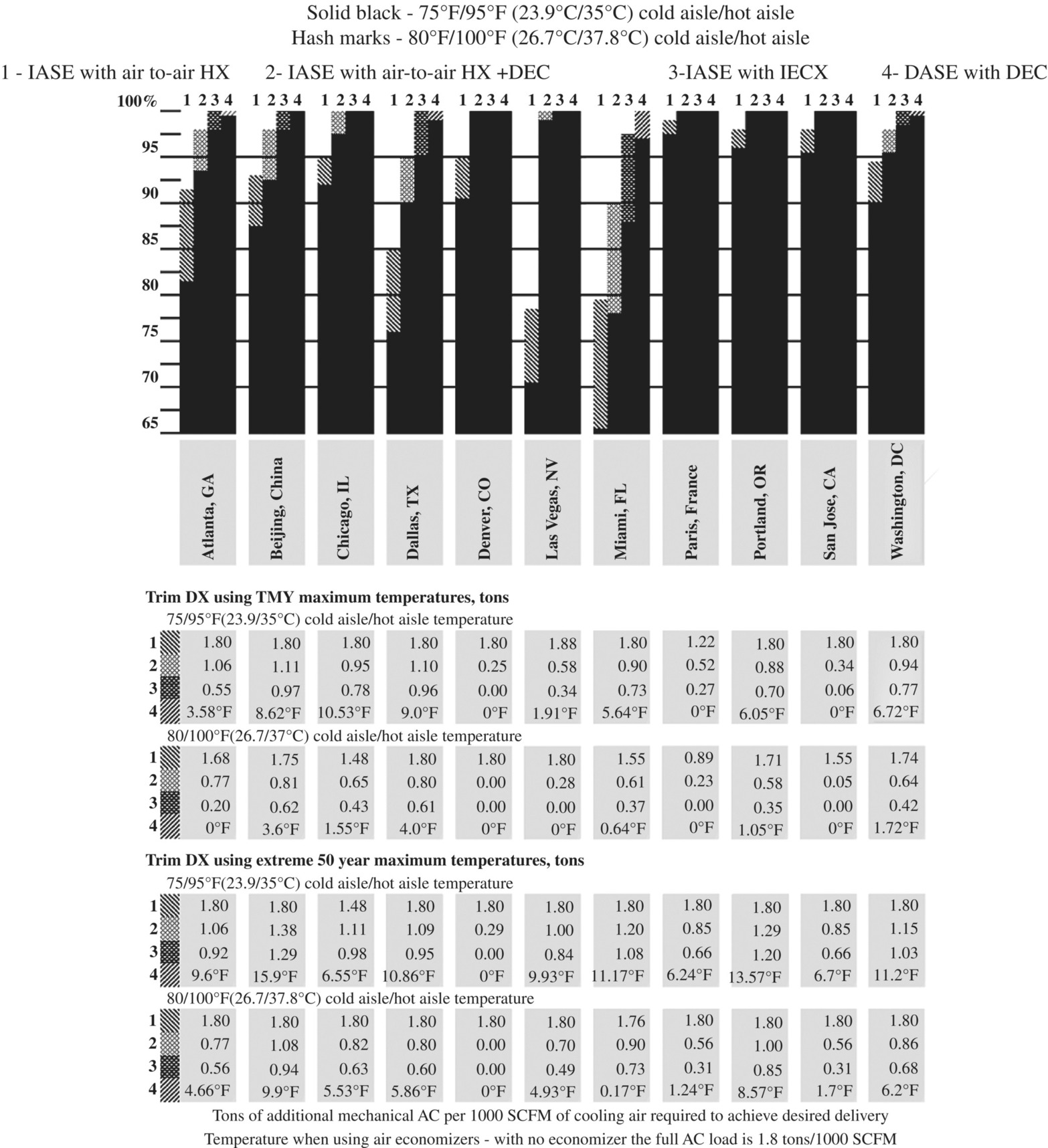
FIGURE 13.12 Annualized economizer cooling capability based on TMY3 (Typical Meteorological Year) data
To aid in using Figure 13.12, take the following steps:
- Select the city of interest and use that column to select the following parameters.
- Select either TMY maximum or 50‐year extreme section for the ambient cooling design.
- Select the desired cold aisle/hot aisle temperature section within the section selected in step 2.
- Compare the trim mechanical cooling required for each of the four cooling systems under the selected conditions.
Dallas, Texas, using an AHX, represented by the no. 1 at the top of the column, will be used as the first example. Operating at a cold aisle temperature of 75°F and a hot aisle of 95°F, represented by the solid black bars, 76% of the cooling ton‐hours during the year will be supplied by the economizer. The other 24% will be supplied by a cooling coil. The size of the trim mechanical cooling system is shown in the lower part of the table as 1.8 tons/1000 standard cubic feet per minute (SCFM) of cooling air, which is also the specified maximum cooling load that is required to dissipate the IT heat load. Therefore, for the AHX in Dallas, the amount of trim cooling required is the same tonnage as would be required when no economizer is used. That is because the TMY3 design db temperature is 104°F, well above the RA temperature of 95°F. Even when the cold aisle/hot aisle setpoints are raised to 80°F/100°F, the full capacity of mechanical cooling is required. If a DEC (represented by no. 2 at top of column) is placed in the ScA (TMY3 maximum wb temperature is 83°F), then 90% of the yearly cooling is supplied by the economizer and the trim cooling drops to 1.1 tons/1000 scfm from 1.8 tons.
For the second example, we will examine Washington, D.C., where the engineer has determined that the design ambient conditions will be based on TMY3 data. Using 75°F/95°F cold aisle/hot aisle conditions, the IECX and DASE with DEC, columns no. 3 and no. 4, can perform 98 and 99% of the yearly cooling, respectively, leaving only 2 and 1% of the energy to be supplied by the mechanical trim cooling. The AHX (no. 1) accomplishes 90% of the yearly cooling, and if a DEC (no. 2) is added to the scavenger airstream, the combination does 96% of the cooling. The trim cooling for heat exchangers 1, 2, and 3, respectively, is 1.8, 0.94, and 0.77 tons where 1.8 is full load tonnage. Increasing the cold aisle/hot aisle to 80°F/110°F allows no. 3 and no. 4 to supply all of the cooling with the economizers, and reduces the amount of onboard trim cooling for 1 and 2.
It should be apparent from Figure 13.11 that even in hot and humid climates such as Miami, Florida, economizers can provide a significant benefit for DCs. As ASHRAE standard 90.4 is adopted, selecting the right economizer cooling system should allow a design to meet or exceed the required mechanical efficiency levels. In addition, the economizers presented in this section will become even more desirable for energy savings as engineers and owners become more familiar with the recently introduced allowable operating environments A1 through A4 as shown on the psychrometric charts of Figures 13.2 and 13.4. In fact, if the conditions of A1 and A2 were allowed for a small portion of the total operating hours per year, then for no. 2 and no. 3 all of the cooling could be accomplished with the economizers, and there would be no requirement for trim cooling when using TMY3 extremes. For no. 4, the cooling could also be fully done with the economizer, but the humidity would exceed the envelope during hot, humid periods.
There are instances when the cooling system is being selected and designed for a very critical application where the system has to hold space temperature under the worst possible ambient cooling condition. In these cases the ASHRAE 50‐year extreme annual design conditions are used as referred in Chapter 14 of Ref. [3] and designated as “complete data tables” and underlined in blue in the first paragraph. These data can only be accessed by means of the disk that accompanies the ASHRAE Handbook. The extreme conditions are shown in Table 13.2, which also includes for comparison the maximum conditions from TMY3 data.
TABLE 13.2 Design temperatures that aid in determining the amount of trim cooling
| 50‐year extreme | Maximum from TMY3 data | |||||||
|---|---|---|---|---|---|---|---|---|
| db | wb | db | wb | |||||
| °F | °C | °F | °C | °F | °C | °F | °C | |
| Atlanta | 105.0 | 40.6 | 82.4 | 28.0 | 98.1 | 36.7 | 77.2 | 25.1 |
| Beijing | 108.8 | 42.7 | 87.8 | 31.0 | 99.3 | 37.4 | 83.2 | 28.4 |
| Chicago | 105.6 | 40.9 | 33.3 | 28.5 | 95.0 | 35.0 | 80.5 | 26.9 |
| Dallas | 112.5 | 44.7 | 82.9 | 28.3 | 104.0 | 40.0 | 83.0 | 28.3 |
| Denver | 104.8 | 40.4 | 69.3 | 20.7 | 104.0 | 40.0 | 68.6 | 20.3 |
| Las Vegas | 117.6 | 47.6 | 81.3 | 27.4 | 111.9 | 44.4 | 74.2 | 23.4 |
| Miami | 99.4 | 37.4 | 84.7 | 29.3 | 96.1 | 35.6 | 79.7 | 26.5 |
| Paris | 103.2 | 39.6 | 78.8 | 26.0 | 86.0 | 30.0 | 73.2 | 22.9 |
| Portland | 108.1 | 42.3 | 86.4 | 30.2 | 98.6 | 37.0 | 79.3 | 26.3 |
| San Jose | 107.8 | 42.1 | 78.8 | 26.0 | 96.1 | 35.6 | 70.2 | 21.2 |
| Washington, D.C. | 106.0 | 41.1 | 84.0 | 28.9 | 99.0 | 37.2 | 80.3 | 26.8 |
Using the 50‐year extreme temperatures of Table 13.2, the amount of trim cooling, which translates to additional initial capital cost, is shown in the lower portion of Figure 13.12. All values of cooling tons are per 1000 scfm (1699 m3/h) with a ΔT of 20°F (11.1°C). For the DASE with DEC designated as number 4, instead of showing tons, temperature rise above desired cold aisle temperature is given.
From a cost standpoint, just what does it mean when the economizer reduces or eliminates the need for mechanical cooling? This can best be illustrated by comparing the mechanical partial PUE (pPUE) of an economizer system to that of a modern conventional mechanical cooling system. Mechanical pPUE in this case is a ratio of (IT cooling load + power consumed in cooling IT load)/(IT load). The mechanical pPUE value of economizers ranges from 1.07 to about 1.3. For refrigeration systems the value ranges from 1.8 to 2.5. Taking the average of the economizer performance as being 1.13 and using the lower value of a refrigeration (better performance) system of 1.8, the economizer uses only 1/6 of the operating energy to cool the DC when all cooling is performed by the economizer.
As an example of cost savings, if a DC operated at an IT load of 5 MW for a full year and the electrical utility rate was $0.10/kW‐h, then the power cost to operate the IT equipment would be $4,383,000/year. To cool with mechanical refrigeration equipment with a pPUE of 1.80, the cooling cost would be $3,506,400/year for a total electrical cost of $7,889,000. If the economizer handled the entire cooling load, the cooling cost would be reduced to $570,000/year. If the economizer could only do 95% of the full cooling load for the year, then the cooling cost would still be reduced from $3,506,400 to $717,000—a reduction worth investigating.
13.5 CONVENTIONAL MEANS FOR COOLING DATACOM FACILITIES
In this chapter we have discussed techniques for cooling that first and foremost consider economization as the principal form of cooling. There are more than 20 ways to cool a DC using mechanical refrigeration with or without some form of economizer as part of the cooling strategy. References [4] and [5] are two articles that cover these various mechanical cooling techniques. Also, Chapter 20, Data Centers and Telecommunication Facilities, of Ref. [6] discusses standard techniques for DC cooling.
13.6 A NOTE ON LEGIONNAIRES' DISEASE
IEC is considered to share the same operating and maintenance characteristics as conventional DEC, except that the evaporated water is not added to the process air. As a result, ASHRAE has included IEC in chapter 53, Evaporative Cooling, of Ref. [5]. Below is an excerpt from the handbook:
Legionnaires' Disease. There have been no known cases of Legionnaires' disease with air washers or wetted‐media evaporative air coolers. This can be attributed to the low temperature of the recirculated water, which is not conducive to Legionella bacteria growth, as well as the absence of aerosolized water carryover that could transmit the bacteria to a host. ()
ASHRAE Guideline 12‐2000 [7]
IECs operate in a manner closely resembling DECs and not resembling cooling towers. A typical cooling tower process receives heated water at 95–100°F, sprays the water into the top of the tower fill material at the return temperature, and is evaporatively cooled to about 85°F with an ambient wb of 75°F before it flows down into the sump and is then pumped back to the process to complete the cycle. The ScA leaving the top of a cooling tower could be carrying with it water droplets at a temperature of over 100°F. On the other hand, an IEC unit sprays the coolest water within the system on top of the IECX surface, and then the cool water flows down over the tubes. It is the cooled water that totally covers the tubes that is the driving force for cooling the process air flowing within the tubes. The cooling water then drops to the sump and is pumped back up to the spray nozzles, so the water temperature leaving at the bottom of the HX is the same temperature as the water being sprayed into the top of the IECX. On hot days, at any point within the IECX, the water temperature on the tubes is lower than the temperature of either the process airstream or the wetted scavenger airstream. From an ETL, independently tested IECX, similar to the units being used in DCs and operating at DC temperatures, high ambient temperature test data show that the sump water temperature, and therefore the spray water temperature, is 78°F when the return from the hot aisle is 101.2°F and the ambient ScA is 108.3/76.1°F. Or the spray water temperature is 1.9°F above ambient wb temperature.
In addition to having the sump temperature within a few degrees of the wb temperature on hot days, thus behaving like a DEC, there is essentially, with proper design, no chance that water droplets will leave the top of the IEC unit. This is because there is a moisture eliminator over the IECX and then there is a warm condenser coil over the eliminator (on the hottest days the trim DX will be operating and releasing its heat into the scavenger airstream, which, in the unlikely event that a water droplet escapes through the eliminator, that droplet would evaporate to a gas as the air heats through the condenser coil).
So, IEC systems inherently have two of the ingredients that prevent Legionella: cool sump and spray temperatures and only water vapor leaving the unit. The third is to do a good housekeeping job and maintain the sump area so that it is clean and fresh. This is accomplished with a combination of sump water bleed‐off, scheduled sump dumps, routine inspection and cleaning, and biocide treatment if necessary. With good sump maintenance, all three criteria to prevent Legionella are present.
REFERENCES
- [1] ASHRAE. Thermal Guidelines for Data Processing Environments. 4th ed. Atlanta: ASHRAE; 2015.
- [2] ASHRAE. ASHRAE Handbook‐Systems and Equipment. Atlanta: American Society of Heating Refrigeration and Air Conditioning Engineers, Inc.; 2020.
- [3] ASHRAE. ASHRAE Handbook‐Fundamentals. Atlanta: American Society of Heating Refrigeration and Air Conditioning Engineers, Inc.; 2017.
- [4] Evans T. The different technologies for cooling data centers, Revision 2. Available at http://www.apcmedia.com/salestools/VAVR‐5UDTU5/VAVR‐5UDTU5_R2_EN.pdf. Accessed on May 15, 2020.
- [5] Kennedy D. Understanding data center cooling energy usage and reduction methods. Rittal White Paper 507; February 2009.
- [6] ASHRAE. ASHRAE Handbook‐Applications. Atlanta: American Society of Heating Refrigeration and Air Conditioning Engineers, Inc.; 2019.
- [7] ASHRAE Standard. Minimizing the risk of legionellosis associated with building water systems, ASHRAE Guideline12‐2000, ISSN 1041‐2336. Atlanta, Georgia: American Society of Heating, Refrigerating and Air‐Conditioning Engineers, Inc.
FURTHER READING
- Atwood D, Miner J. Reducing Data Center Cost with an Air Economizer. Hillsboro: Intel; 2008.
- Dunnavant K. Data center heat rejection. ASHRAE J 2011; 53(3):44–54.
- Quirk D, Sorell V. Economizers in Datacom: risk mission vs. reward environment? ASHRAE Trans 2010; 116(2):9, para.2.
- Scofield M, Weaver T. Using wet‐bulb economizers, data center cooling. ASHRAE J 2008; 50(8):52–54, 56–58.
- Scofield M, Weaver T, Dunnavant K, Fisher M. Reduce data center cooling cost by 75%. Eng Syst 2009; 26(4):34–41.
- Yury YL. Waterside and airside economizers, design considerations for data center facilities. ASHRAE Trans 2010; 116(1):98–108.
