An Introduction to the Fundamentals of Database Systems
Publisher Summary
This chapter introduces the fundamental database concepts. It discusses different database models and relevance to database middleware. It provides examples of real-world embedded database middleware. A database management system (DBMS), also commonly referred to as simply a database system, is another scheme that can be used to reliably and efficiently manage data within an embedded system. A database system can be accessible and directly utilized by the embedded system’s user, by other middleware software, by applications in the system to manage data for the application, or some combination of the above. Database systems are commonly used instead of file systems within a design when using a file system instead of a DBMS would result in a great deal of redundancy of the same data in different files. There are several different database design schemes that can be implemented in a particular database system. In order to understand a database system design, determine which database design is the right choice for an embedded device, as well as understand the impact of a database on a particular device—it is important to first understand the fundamental components that make up a database system.
Chapter Points
• Introduces fundamental database concepts
• Discusses different database models and relevance to database middleware
7.1 What is a Database System?
Like a file system, a database management system (DBMS), also commonly referred to as simply a database system, is another scheme that can be used to reliably and efficiently manage data within an embedded system. A database system can be accessible and directly utilized by the embedded system’s user, by other middleware software, by applications in the system to manage data for the application, or some combination of the above. Database systems are commonly used instead of file systems within a design when using a file system instead of a DBMS would result in a great deal of redundancy of the ‘same’ data in ‘different’ files. So, when using a file system introduces the challenge of insuring that redundant data within the system need to be constantly updated to insure consistency – then a database as an alternative option is commonly considered. A database is also considered, for example, when managing access to the same data within a file system requires additional overhead when working to insure reliable and secure access to more than one overlying software component and/or user to that data, without corrupting that data in the process.
Keep in mind, a particular database design may not 100% eliminate redundant data. In fact, a database based upon for example the relational model may introduce some redundant data. A database can be used to ensure that the redundant data remain consistent. For example, an IP address for a given device can be changed everywhere that IP address is used via an efficient look up (indexes) scheme. Remember, a database is not intended to be a direct “alternative” to a file system, and in some DBMS designs is most often implemented on top of the file system. It is simply an approach commonly used instead of direct manipulation of files within a file system.
At the highest level, a database system is made up of two major components: (1) the database(s) and (2) the overlying middleware and/or application software used to manage the access to the database(s). Within the database system, a database manages data by allowing for:
• the organization, storage, and management of interrelated data
• querying of data via a query language
Thus, in contrast to the wide variety of data that is typically stored in a file system, in the case of data stored in a database system, simply put the data are interrelated. As with file systems, data within a database system are not limited to the data belonging to users, other middleware, and/or applications utilizing the database system. This is because an underlying infrastructure must be in place to store the data, manipulate these data, insure the integrity of the data, and provide secure access to these data.
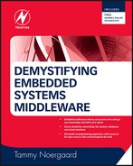
As with file systems, depending on the database the storage medium can be volatile RAM, and/or non-volatile memory such as: Flash, CD, floppy disk, and hard disk to name a few. Keep in mind that the database itself and the data it manages may or may not reside on the same device. This means, as shown in Figure 7.1, the data the database manages can be located on some type of hardware storage medium located on the embedded system board or located on some other storage medium accessible to the embedded system (i.e., over a network, on a CD, etc.)
Ultimately, managing data within the database is accomplished by utilizing metadata stored within the database system’s data dictionary region. Metadata is all the additional components that the database middleware uses to maintain the context, or state, of the system, for example run-time structures describing active connections, and other “metadata” components that are specific to the architecture of that particular database. The database’s data dictionary is simply a region which contains information that describes, for example:
• the type and attributes of data being stored within the database
• the structure and location of the data within the database
• the type(s) of object(s) storing the data
• database features and constraints, such as triggers and referential integrity
• details to manage database users, such as permissions and accounts details.
To be useful in the embedded device, a database system must then have a reliable and efficient ‘data modeling’ scheme to create the components that store data, process data, and locate the data these metadata describes on the embedded device’s storage medium(s). The data model drives how the fundamental database subsystems are designed internally, and ultimately how the user/application data will be managed. There are several types of data models used in real-world database designs on the market today. However, the most common schemes implemented within database systems on embedded devices are based upon a record-based model, an object-based model, or some hybrid combination of both.
7.2 Record-based versus Object-oriented Database Models
A record-based database system structures data as records within the database, and then relates records to one another via the data contained within the record. Depending on the internal database design, these records can be fixed-length or variable-length. While there are several types of record-based database models, one of the most common is the relational database model – where records are grouped and organized into more complex tables (note: tables are not more complex than records; they are simply groupings of like records). Each table within the relational database model has a unique name. Each table then represents a unique set of relationships, where the data contained within each row represents a relation.
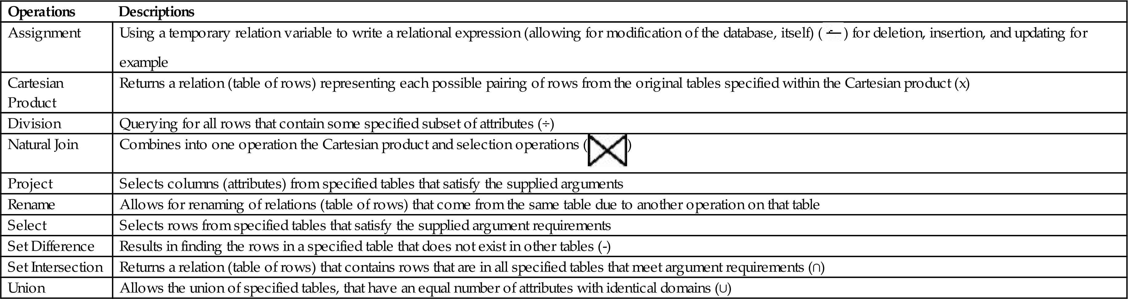
The types of columns that make up the tables within a relational database are the attributes of the data within that table. In Figure 7.2, attributes include ‘CDId’, ‘CDName’, ‘Genre’, ‘Price’, and ‘NumberInStock’ for example. When defining a table and its corresponding attributes, domains for these attributes are specified that define the allowed type of data. For example, the domain for ‘CDId’ may be defined to be unique integers assigned to independent compact disks (CDs), whereas the domain for ‘CDName’ may be defined as a set of CD names of an alphanumeric string of some ‘n’ maximum length. Thus, tables within a relational database can then be related to other tables via the shared attributes (keys) within a table, such as the example shown in Figure 7.2.

Overlying middleware software, application software, and/or a user directly communicates with a database system via some type of programming language (see Figure 7.3a) and via database system APIs. Basically, every database system has some type of DML (data-manipulation language) and/or Data Definition Language (DDL) to allow communication. The DML, as its name implies, is what allows for the manipulation of the data within a database – meaning the reading, writing, and deleting of these data within the database. DDLs are used to specify a set of definitions that define the underlying database scheme itself. So, to function within the embedded device, the database system uses the DML and DDL to translate and understand all that is required of it. Everything from managing the structure of the database to actually querying the data contained within is done via communicating through the DML, the DDL, or a language that acts as some combination of both a DML and DDL.

An example of a common real-world language utilized in many database systems, especially dominant in the relational database sphere, is based on a common industry standard called SQL (structured query language). SQL is a type of computer database language, meaning a language used to create, maintain and control a database. In reality, SQL is much more than a query language; it has DML, DDL and DCL (data control language) elements within it. For example, the DML includes INSERTIUPDATE/DELETE statements in addition to SELECT statements for querying. The Perst database system used as a real-world example in this chapter utilizes a procedural query language based on a derivation of the SQL standard, called JSQL (see Figure 7.3b).

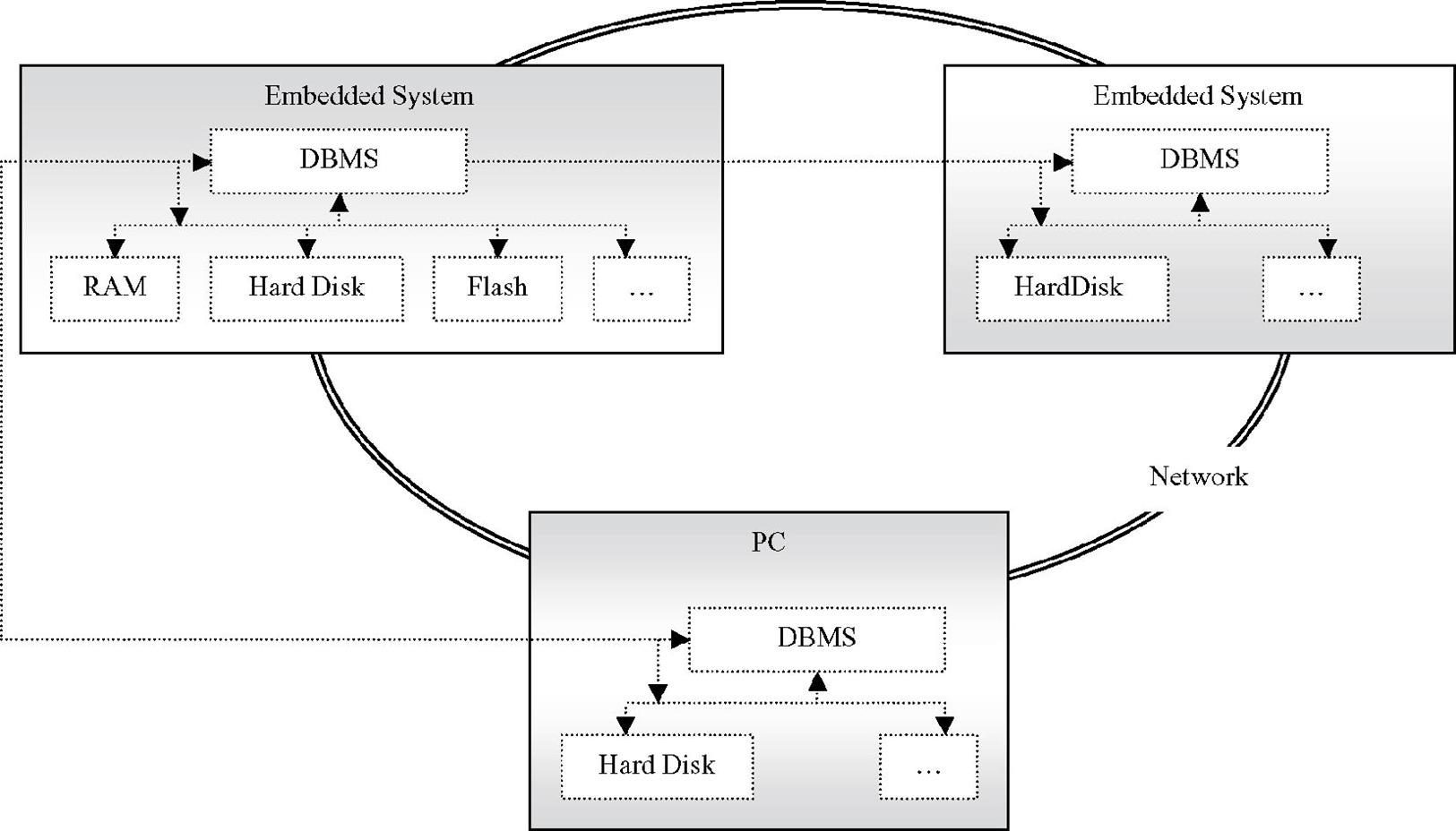
In general, database query languages are considered either non-procedural (where only the specific data within the database are specificed) or procedural (where both the data and the program logic to perform on the data can be specified). Procedural refers to the presence of logic statements like if-then-else and do-while. Operations are selection, projection, join, insert, update, and delete. Examples of some of the operations that act as foundations for procedural query languages are shown in Table 7.1.
Table 7.1
Examples of Procedural Query Language Operations
| Operations | Descriptions |
| Assignment | Using a temporary relation variable to write a relational expression (allowing for modification of the database, itself) ( |
| Cartesian Product | Returns a relation (table of rows) representing each possible pairing of rows from the original tables specified within the Cartesian product (x) |
| Division | Querying for all rows that contain some specified subset of attributes (÷) |
| Natural Join | Combines into one operation the Cartesian product and selection operations ( |
| Project | Selects columns (attributes) from specified tables that satisfy the supplied arguments |
| Rename | Allows for renaming of relations (table of rows) that come from the same table due to another operation on that table |
| Select | Selects rows from specified tables that satisfy the supplied argument requirements |
| Set Difference | Results in finding the rows in a specified table that does not exist in other tables (-) |
| Set Intersection | Returns a relation (table of rows) that contains rows that are in all specified tables that meet argument requirements (∩) |
| Union | Allows the union of specified tables, that have an equal number of attributes with identical domains (∪) |
SQL itself is composed of a combination of both a DML and DDL. Meaning, SQL is used for everything from defining and deleting relations to executing commands for modifyng the database (deleting data, inserting data, etc.) to insuring data integrity and security via specifying access rights to managing overall transactions. For creating the table in Figure 7.XX, the SQL expression is generally based upon the structure ‘create table x (A1, D1, A2, D2, A3, D3,… An, Dn, {integrity-contsrainti},…)’ where ‘x’ is the name of the table, Ai define the attributes of the table, and Di are defining the domains of these attributes. Integrity-constrainti is how to insure that changes made to the database do not result in some type of corruption. So, for example, an SQL expression for creating CDTable could be:
For extracting data, generally, SQL expressions are made up of three parts:
1. select, as described in Table 7.1 for the ‘select’ operation relative to attributes to be copied (select A1,A2,A3, … An from…-- Ai is an attribute).
2. from, the Cartesian product that lists relations to be used (select A1,A2,A3, … An from r1,r2,r3, … rn where …. -- ri is a relation).
3. where, the selection predicate (select A1,A2, A3, … An from r1,r2,r3, … rn where P – P is the predicate).
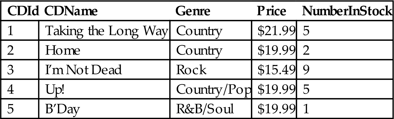
So, for example, given the table in Figure 7.2, to use SQL to find the names of CDs (CDName) that cost less than $20 the SQL expression could look as follows:
and would return all the CDNames listed in Table 7.2 with a price less than $20 (rows two through five).
Table 7.2
Example of SQL Query and Table
| CDId | CDName | Genre | Price | NumberInStock |
| 1 | Taking the Long Way | Country | $21.99 | 5 |
| 2 | Home | Country | $19.99 | 2 |
| 3 | I’m Not Dead | Rock | $15.49 | 9 |
| 4 | Up! | Country/Pop | $19.99 | 0 |
| 5 | B’Day | R&B/Soul | $19.99 | 1 |

For modifying the database, SQL expressions are generally made up of:
1. (type of database modification), i.e., ‘delete from’, ‘insert into’, ‘update’.
2. where, the selection predicate (select A1,A2,A3, … An from r1,r2,r3, … rn where P – P is the predicate).
So, an SQL example could be updating a row into the CDTable (Table 7.3) with the following SQL expression that would increase the number of CDs in stock for one of the listed CDs:
Table 7.3
Example of SQL Query and Updating Table
| CDId | CDName | Genre | Price | NumberInStock |
| 1 | Taking the Long Way | Country | $21.99 | 5 |
| 2 | Home | Country | $19.99 | 2 |
| 3 | I’m Not Dead | Rock | $15.49 | 9 |
| 4 | Up! | Country/Pop | $19.99 | 5 |
| 5 | B’Day | R&B/Soul | $19.99 | 1 |
Record-based ‘hierarchical’ database systems can also implement trees that use pointers to define relations between the different records (see Figure 7.4). Another example is a record-based ‘network’ database model, where records are related via links into arbitrary graphs.
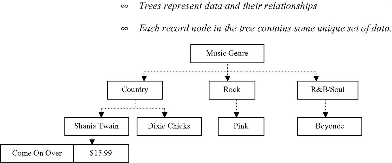
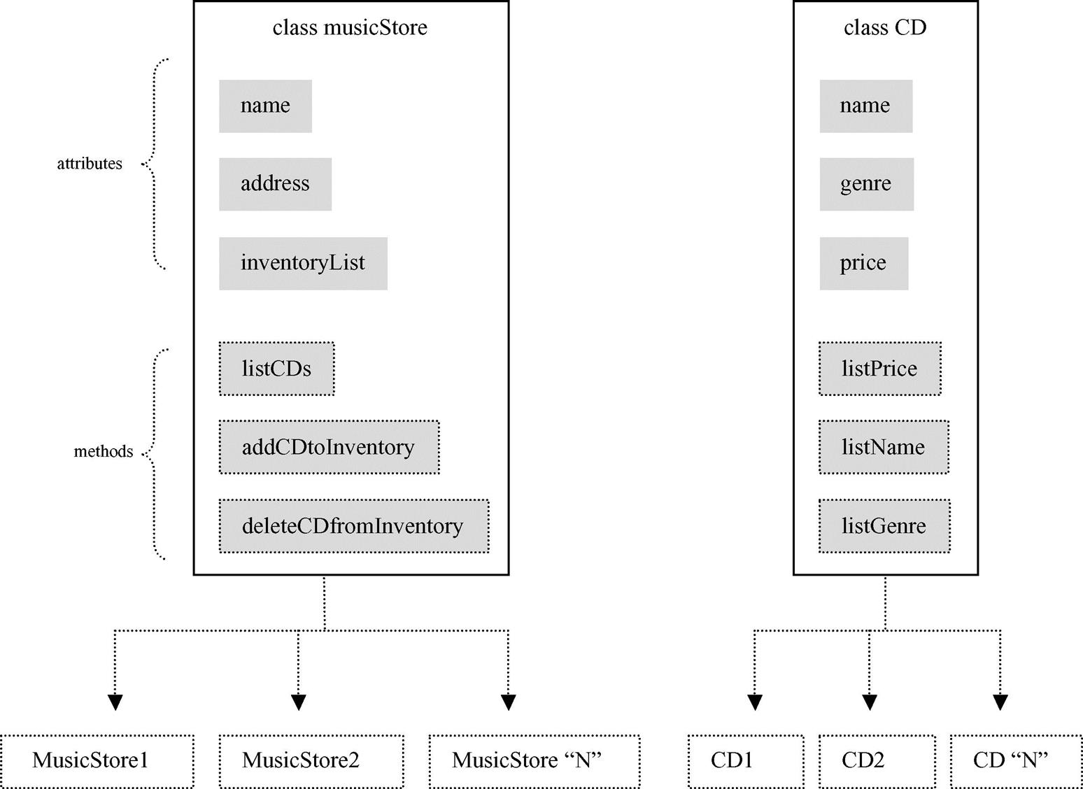
There are several types of object-based models in database system design, from object-oriented to entity/relationship to semantic. However, all of these object-oriented models are in general based on object-oriented programming fundamentals where all components within a database system are considered objects. Within this type of database, all objects encapsulate state and associated behavior data. Another example is a record-based “network” database model, where records are related via links (pointers) into arbitrary graphs.” An object state is simply some set of parameters that defines the attributes of that object. The behavior of objects is defined via their methods (functions) that operate on the object’s state data.
The various types of relationships between these objects are defined via their classes as shown in Figure 7.5. A class is simply a way to group objects that share identical states (attributes) and behaviors (methods). Basically, objects are created via the relative instantiation of a class. Via classes then, more complex relationships between data are supported, such as inheritance for example, which allows new sets of objects (classes) to be derived from a current class. Objects, and inherently their classes in which they are instantiated from, are the basis in which database queries are made. In some database systems these queries are implemented via an existing DML that is expanded to provide object-oriented support, whereas other database solutions affect queries through an application programming interface (API) that is used within an objectoriented programming language such as Java or C#.”
Databases can also be implemented with a design that is some hybrid combination of both object-based and record-based schemes – the most common type being object-relational databases. Overlying requirements on these types of hybrid databases typically include having powerful querying capabilities, being able to manage complex data (i.e., CAD or multimedia data), and decent performance on handling a large number of database accesses. This means that these hybrid models exist to support requirements that would utilize the best of both worlds.
For example, relational database models support simple data types and the use of the ‘safer’ querying languages (like SQL) that provide better database protection. Object-oriented models provide the support of more complex data types and offer more flexility via the use of conventional programming languages (e.g. C/C++ or Java). The hybrid object-relational databases provide support for both the simpler and complex data types in synergy with data querying features typically only found in relational databases in addition to object-oriented data modeling capabilities. The open source Perst database example, used in this chapter, is a real-world example based on a hybrid object-relational approach.
7.3 Why Care About The Different Database Models?
It is important for a middleware developer to understand the different database models, since these different database models created were done to meet different requirements. The model a particular database design adheres to determines how that database logically organizes data, defines the constraints on the data, and the inter-relationships supported. Here it is important to understand a database scheme at the logical level in order to understand how data are represented and managed. This means understanding whether it is via some set of tables within a relational (record-based) type of database versus within an object-oriented database’s set of defined classes and instantiated objects. Furthermore, understanding the type of data structures and relative operations used to manage within a database design is key, for example, to predicting the type of performance to expect of the database given the underlying software and hardware components.
The database system itself then implements the data model, via the syntax provided by its language. There is not one database solution that fits all embedded systems’ needs. So developers need to understand the pros and cons of each design to insure the database approach is one that maximizes the strengths of its internal design. For example, some database models best support functions that include monitoring inventory and/or managing lists of sales customers, such as the relational database model, for example. This type of database is the approach of choice when data management requirements support that the database is not expected to make major changes too often, and standard operations on data are all that will typically be required (i.e., create table, update table, and so on). Given these standard operations, transactions on data are then expected to be atomic and of shorter duration. The relational database model is also functioning at its best when the data are typically similar in size and structure, allowing for these data to be managed via smaller, fixed-length records.
Other types of database models, such as the object-oriented approach, better support needs relative to complex object graphs such as found in social networking, audio/video multimedia requirements and engineering functions such as CAD (computer-aided design). Object-oriented databases support the management of more complex objects with more freedom to support varying types of data. Databases based on this model also provide better support for non-atomic, asynchronous transactions. Another strength to object-oriented-based database models is considered to be the ability to manage an object (and associated data) with less risk of impacting and corrupting other database components. This is because of the underlying messaging scheme inherent in this approach, where an object’s interface (and associated data) can only be accessed and manipulated via some set of messages the object will have defined as acceptable for processing.
In short, the goal of any database design is to successfully manage data without unnecessary redundancy, as well as to insure the integrity of these data, and manage them efficiently. If, given the specific requirements, a particular database design utilized in a real-world system results in:
it is time for the developer to investigate a different approach.
7.4 The Fundamentals of Database Design: The First Steps
The first steps to understanding an embedded database design are as follows:
Step 1. As with any other middleware component – understand what the purpose of the database is within the system and how it achieves this purpose. Then, simply keep this in mind regardless of how complex a particular database implementation is. As introduced at the start of this chapter, the purpose of a database is to manage data stored on some type of storage medium located within the embedded device and/or some remotely accessible storage medium, and modern database designs can achieve this in a few different ways.
Step 2. Understand the APIs that are provided by a DBMS and the associated database in support of a database’s inherent purpose. These APIs can, of course, differ from database to database, but in general include some set such as the open source example shown in Figures 7.6a and 7.6b.
Step 3. Using the Embedded Systems Model, define and understand all required architecture components that a database requires, specifically:
Step 3.1. Know your database-specific standards, as discussed in Chapter 3.
Step 3.2. Understand the hardware (see Chapter 2). If the reader comprehends the hardware, it is easier to understand why a particular database implements functionality in a certain way relative to the storage medium, as well as the hardware requirements of a particular database implementation.
Step 3.3. Define and understand the specific underlying system software components, such as the available device drivers supporting the storage medium(s) and the operating system API (see Chapter 2).
Step 4. Define the database architecture models on the market today, based on an understanding of the generic database models, and then define and understand what type of functionality and data exist at each layer. This includes database-specific data, such as data structures and the functions included at each layer.


7.5 Real-world Database System Model
When an application or user initiates communication, then an embedded database system contains a number of components to process this incoming communication. What these components are and how these components are designed essentially determine what underlying system software and hardware requirements need to be met in order to utilize them successfully within a design. So, to start, it is recommended the reader begin to familiarize themselves with these components. Figure 7.7 shows a general database systems model made up of some combination of a

An incoming query can impact the data within the database system, as well as trigger actions that impact the structure of the database itself. Database systems typically group incoming queries, as well as other database system actions in general, into independent, atomic tasks called transactions. In order to manage transactions, a transaction manager resides within the system to support:
1. Scheduling, which manages multiple concurrent, independent transactional database system tasks. Depending on the database system, an underlying operating system and/or virtual machine’s scheduler is utilized or an independent scheduler may be implemented by the database system’s designers themselves. Scheduling within a Java virtual machine (JVM), utilized by the open source Java-based Perst example used in the chapter, was discussed further in Chapter 6.
2. Logging and Recovery, which is responsible for insuring that the database can be recovered from mid-transactional failures via utilizing logs kept on the transactions and being able to rollback to a non-corrupted version of the database system.
For database systems based on (or implementing) SQL, the query coming into the database system is first received and translated by some type of query compiler. This query compiler is responsible for translating DML (data-manipulation language) and/or Data Definition Language (DDL) incoming queries for processing. After translation, the query compiler transmits the result, commonly referred to as the query plan, to the execution engine for further processing. Some sample code translating JSQL in Perst is shown in Figure 7.8a.


Upon receiving the query plan from the query compiler, the execution engine actually processes the actions within the plan to manage the data request. The execution engine communicates and transmits requests to a resource manager that manages the indices, records, files, and/or objects (depending on the database design) relative to the data being processed. In the case of the open source Java-based Perst example used in the chapter, the Java virtual machine’s execution engine is mainly utilized and is discussed further in Chapter 6.
7.5.1 Resource Manager
A resource manager is responsible for keeping track of the data within the data structures of the database, to allow for efficient retrieval of data from storage via the buffer and storage manager. Relative to the buffer and storage management (introduced in the next section), while some database designs will utilize their own scheme for managing data directly on the hardware, in other database systems the storage and buffer manager is actually the file system residing on the embedded device, and it is the file system APIs that are utilized by the overlying database system layers.
This is important because, for example, a relational database that utilizes an underlying file system will do so by mapping its internal records into files sequentially or some other method such as some indexing or hashing approach. In this case, how this type of database manages its records within these files given the underlying hardware, and the file internal design system itself, will impact how the database performs. Specifically, it is relative to overhead, meaning computing how much additional compile and runtime memory is required for the particular scheme to execute efficiently, as well as how much time it takes to locate and access these records – then add, delete, or modify data within.
There are several indexing and hashing algorithms that can be implemented into a database design to insure efficiency and avoid overhead when searching for data. Indexing schemes involve traversing some type of index ‘structure’ to insert, delete, and modify data. Hashing schemes involve the use of a function to calculate the data’s address in memory directly.
In general, indexing schemes are based upon individual indices being assigned to data – records and/or objects depending on the type of database (relational, object-oriented, object-relational hybrid, for example). The indices are essentially the fundamental components used within indexing resource management schemes to organize and track data. For example, a B+-tree index is a multilevel index in the form of a tree that is made up of different types of nodes, specifically some combination of root, non-leaf, and leaf nodes. As shown in Figure 7.8b, a B+-tree node is typically made up of key values (K1, K2, … Kn-1) and pointers (P1, P2, … Pn). Key values within a node are the one or more sorted attributes used to search for another node within the B+-tree or the data itself. Non-leaf node pointers are references to the child nodes with the relative search key values less than (on the left branch) or greater than (on the right branch). The number of pointers within a ‘non-leaf’ node are between ‘n/2’ and ‘n’, thus having between ‘n/2’ and ‘n’ number of child nodes. Except for the last pointer within a leaf node (Pn), leaf node pointers P1 …Pn-1 reference the data with the relative search key value. The last pointer (Pn) within a leaf node is used to link to another leaf node.

So, traversing a B+-tree for a particular query retrieving all data with the search key value ‘x’, for example, requires traversing the tree from the root to the desired leaf node. This means starting at the root node of the tree and comparing to search keys K1, K2, … Kn to search key ‘x’. The closest root node search key value that is greater than ‘x’ is whose pointer is used to traverse to the next level of the tree. This means, if K2 < ‘x’ < K3, than it is the non-leaf node the pointer P3 is pointing to that is traversed to. Within the non-leaf nodes, the comparison of ‘x’ to search key values within the node continues until arriving at a leaf node that contains the desired search key values.
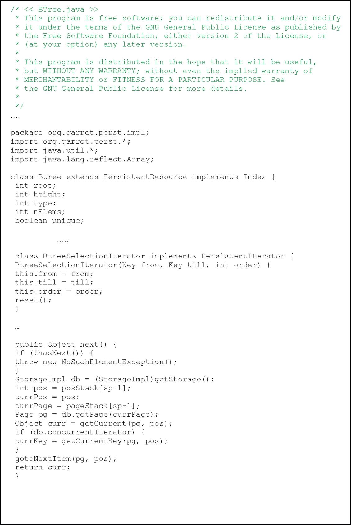
The Perst open source example, shown in Figure 7.8c, is based on a multilevel indexing-based B-tree implementation and a partial snapshot of the Perst B+-tree traversing scheme is shown below.

7.5.2 Buffer and Storage Management
Storage and buffer management is the liaison to underlying system software and manages retrieval and transmission of data to and from the user and the supported storage mediums, including RAM and whatever non-volatile memory is supported by the database. This means it is responsible for managing the requests and the allocation of buffer space in volatile and non-volatile memory. Because access to non-volatile memory is typically much slower than accessing data in volatile memory, the storage and buffer manager for a particular database is based on a scheme that attempts to minimize the number of accesses to non-volatile memory. However, because there is only a limited amount of ‘faster’ volatile memory available to the database, some type of data swapping and replacement scheme must be implemented. The most common types of data swapping and replacement schemes implemented in different database designs are similar to schemes used in underlying operating systems, such as:
• Optimal, utilizes a future reference time to swap out data that won’t be used in the near future
• Least recently used (LRU), data that are used the least recently are swapped out
• FIFO (first in, first out), swaps out data that are the oldest, regardless of how often those data are accessed by the database. FIFO is a simpler algorithm than LRU, but typcially is much less efficient
• Not recently used (NRU), data that are not used within a certain time period are swapped out
• Second chance, a more-complex FIFO scheme that uses a reference bit that sets to ‘1’ when data access occurs. So, if this bit is ‘0’, then associated data are swapped out.
The storage and buffer manager is also what is responsible for managing data integrity within the database, in the cases of synchronizing more than one application/user that must access the database concurrently or recovering system problems, for example. Therefore, some type of scheme that manages the blocking and unblocking of data writes, as well as the write-through of data from volatile memory (i.e., cache, DRAM, etc.) to non-volatile memory (i.e., Flash, Hard Disk, etc.), falls under this database subsystem.
7.6 Utilizing Embedded Databases in Real-world Designs and the Application Layer
Embedded targets constrained by limited memory and processing power typically shy away from the use of a database system to manage data. So, the key is investigating how well the embedded database solution integrates the overlying applications and data management code to allow for better performance, including decreasing the amount of required memory and CPU cycles to process and manage data. When an embedded device can support the costs of introducing a faster master CPU, more memory, and so on, then utilizing an embedded database within the architecture is feasible.
In general, utilizing a database over other types of methods to manage data on an embedded device boils down to the desire for:
• improved data management efficiency
• higher availability and operational continuity
Because the most time-consuming processing relative to a database involves the management of data relative to the non-volatile storage device (be it Flash, Hard Disk, etc.) it is important to understand the importance of having enough cache or even volatile main memory on the target if the team selects an IMDS (in-memory database system) to allow for better performance when managing data, for example. It is also important to understand the database write-through scheme that insures all changes made in volatile memory are saved properly to the non-volatile storage device in the cases of a system failure and power disruptions. This means understanding a particular database system’s scheme for managing redundant data as well as managing the transactions and logging that allows for the ability to insure consistent data and even recover data if a problem occurs with the device.
As with other types of middleware, selecting which embedded database supports the system requirements means insuring the database implementation supports the underlying platform. Figure 7.9 shows a sample snapshot of a datasheet of a real-world embedded database, called eXtremeDB. This datasheet outlines some underlying platform and development tool support information, as well as the type of complex data types that can be supported by eXtremeDB. In the case of the version of eXtremeDB referred to in Figure 7.9, the embedded operating systems that this embedded database has been ported to support include various flavors of vxWorks, Integrity, QNX, and Nucleus embedded OSs to name a few.

7.7 Summary
There are several different database design schemes that can be implemented in a particular database system. In order to understand a database system design, determine which database design is the right choice for an embedded device, as well as understand the impact of a database on a particular device – it is important to first understand the fundamental components that make up a database system. These fundamentals, introduced in this chapter, included what the purpose of a database is, elements that commonly make up a database, and a real-world example of an object-oriented database system scheme implementing some of these elements. The reader can then apply these fundamentals to analyzing database design features, such as:
• maximum amount of memory that is needed by the database system
• support of specific hardware, operating system, or underlying middleware
in order to determine if the database system design is the right one for a particular system, as well as the impact of the database system on the embedded device. This chapter has introduced the basic concepts of database systems design.
The next section of this book will compare different types of middleware, including discussing how to determine which middleware is the best-fit for particular requirements, as well as the hardware and system software requirements when using particular middleware components such as a database system implementation.
7.8 Problems
1. What is the purpose of a database system?
2. All database systems can only manage files located on the embedded system the file system resides on (True/False).
3. What does DBMS stand for? What is the difference between a database system and a DBMS?
4. A database system can utilize a file system within its design (True/False).
5. Outline the four-step model to understanding a database system design.
6. A database system implemented in the system software layer can exist as:
A. Middleware that sits on top of the operating system layer
B. Middleware that sits on top of other middleware components, for example a Java-based file system that resides on a Java Virtual Machine (JVM)
C. Middleware that has been tightly integrated and provided with a particular operating system distribution
7. One or more database systems can be implemented in an embedded system (True/False).
8. Name and describe three data modeling schemes.
9. A database system can manage files on the following hardware:
10. How does an application communicate with a database system?
11. A database system will never require other underlying middleware components (True/False).
12. Draw and describe the layers of the General Database System Model.
13. Name and describe five examples of database system APIs.