The Foundation
Publisher Summary
This chapter introduces the fundamental hardware concepts and terminology of middleware. It identifies the major elements of most underlying system software designs. In order to understand a particular middleware design, to determine which middleware design is the right choice for an embedded device, as well as understand the impact of middleware software on a particular device, it is important to first understand the foundation that underlies the middleware. This foundation includes some combination of the hardware, as well as device drivers, operating systems, and other required middleware components. The user can then apply these fundamentals to analyzing what would be required to get a particular middleware component running in an embedded system, to determine which middleware design is the right one for a particular system, as well as the impact of the file system on the embedded device.
Chapter Points
• Defines what components are required and underlie middleware
• Introduces fundamental hardware concepts and terminology
• Identifies the major elements of most underlying system software designs
Regardless of what middleware is in an embedded system, one of the most powerful approaches is to take the systems approach. This means having a solid technical foundation via defining and understanding all required components that underlie the particular middleware software. Meaning:
1. Understanding the hardware. If the reader comprehends the hardware, it is easier to understand why a particular middleware component implements functionality in a certain way relative to the storage medium, as well as the hardware requirements of a particular middleware implementation.
2. Defining and understanding the specific underlying system software components, such as the available device drivers supporting the storage medium(s) and the operating system API. Underlying system software will be discussed later in this chapter.
Why start with understanding the hardware? Because some of the most common mistakes programmers designing complex embedded systems make that lead to costly delays and problems include:
• being intimidated by the embedded hardware and tools
• treating all embedded hardware like it is a PC-Windows Desktop
• using PCs in place of ‘available’ embedded systems target hardware to do development and testing
• NOT using embedded hardware similar to production hardware, mainly similar I/O, processing power, and memory.
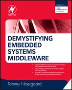
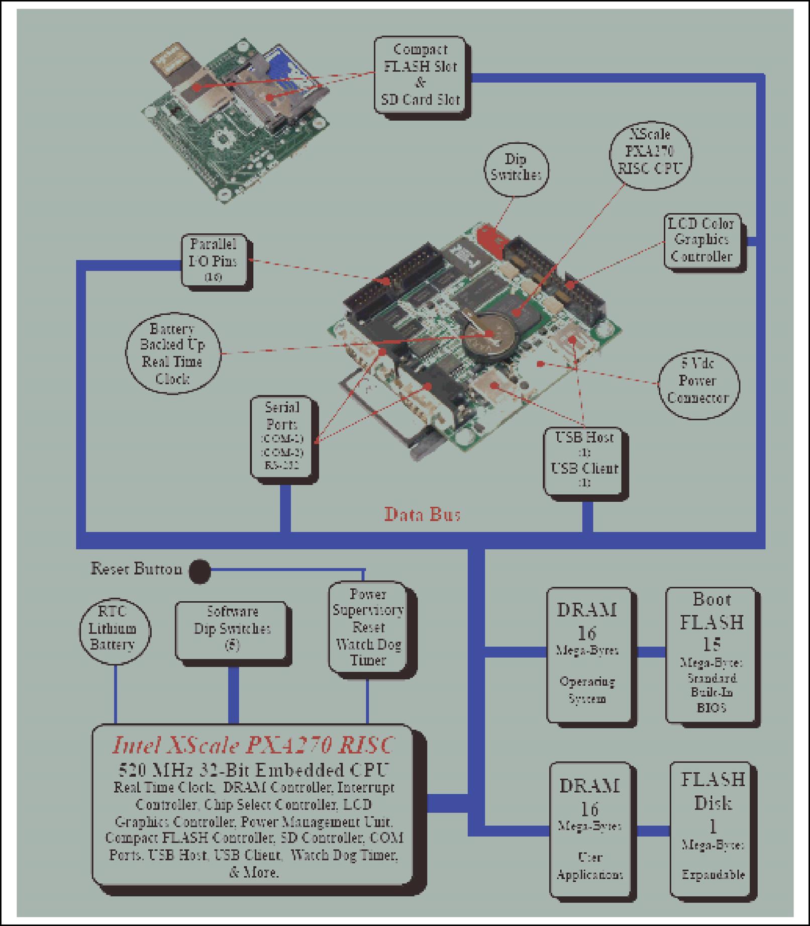
Developing software for embedded hardware is not the same as developing software for a PC or a larger computer system – especially when it comes to including the additional layer of complexity when introducing a middleware component. The embedded systems boards shown in Figures 2.1a-d demonstrate this point of how drastically embedded boards can vary in design.
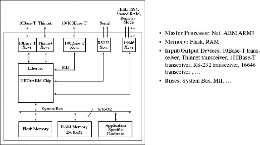
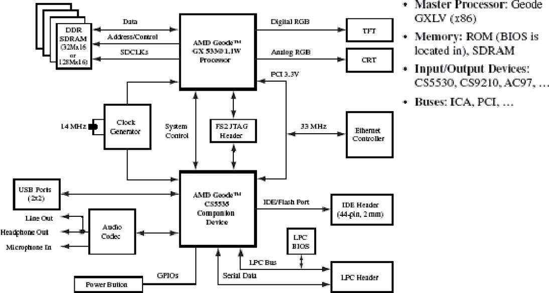

This means each of the boards shown widely varies in terms of the software that can be supported because the major hardware components are different, from the type of master processor to the available memory to the I/O (input/output) devices. Target system hardware requirements depend on the software, especially complex systems that contain an operating system, middleware components, in addition to the overlying application software. So, middleware developers must learn to read the hardware schematics and datasheets to understand and verify all the major components found on an embedded board. This is to insure that the processor design is powerful enough to support the requirements of the software stack, the embedded hardware contains the required I/O, and the hardware has enough of the right type of memory.
2.1 A Middleware Programmer’s Viewpoint – Why Care about Processor Design and I/O?
From the middleware programmer’s point of view, it is critical to care about the processor design and I/O on the target hardware. In the case of processors (whether they are master and/or slave I/O CPUs), there are literally thousands of embedded processors that are differentiated according to their ISAs (instruction set architectures). A processor’s ISA defines everything from the available operations to the operands to addressing modes to interrupt handling, for example. Most embedded processors fall under one of three ISA models:
• Application-specific, such as controller, datapath, finite state machine w/datapath (FSMD), and Java virtual machine (JVM)
• General purpose, such as complex instruction set computing (CISC) and reduced instruction set computing (RISC)
• Instruction-level parallelism, such as single instruction multiple data (SIMD), superscalar machine, very long instruction word computing (VLIW).
It is important for programmers to understand the processors and the ISA design they are based upon. This is because the ability to support a complex middleware solution, and the time it takes to design and develop it, will be impacted by the ISA in terms of available functionality, the cost of the chip, and most importantly the performance of the processor. For example, a programmer’s ability to understand processor performance, and what to look for in a processor’s design according to what needs to be accomplished via software. Processor performance is most commonly defined as some combination of the following:
• Responsiveness, length of elapsed time the processor takes to respond to some event, a.k.a latency
• Availability, the amount of time the processor runs normally without failure
• Reliability, the average time between failures, a.k.a. the MTBF (mean time between failures)
• Recoverability, the average time the processor takes to recover from failure, a.k.a. the MTTR (mean time to recover)
• Throughput, the amount of work the processor completes in a given period of time, a.k.a. the average execution rate (Figure 2.2).
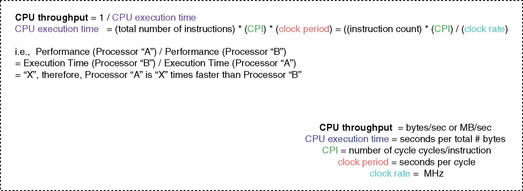
So, for example, given processor performance relative to throughput and managing instruction processing – specifically, the number of clock cycles per second (clock rate), as well as the number of cycle per instruction (CPI). Any internal processor design feature that allows for either an increase in the clock rate or decrease in the CPI will increase the overall performance of a processor. This could include anything from pipelining within the processor’s ALU to selecting a processor based on the instruction-level parallelism ISA model.
In the case of IO subsystems consisting of some combination of transmission medium, ports and interfaces, IO controllers, buses, and the master processor integrated I/O – I/O subsystem performance in terms of throughput, execution time, and response time is key. Programmers need to pay attention not only to the speed of the master processor, but the data rates of the I/O devices, how to synchronize the speed of the master processor to the speeds of I/O, and how I/O and the master processor communicate. Programmers even need to pay attention to buses, meaning from a developer’s viewpoint bus arbitration, handshaking, signal lines, and timing. Bus performance is typically measured via bandwidth where both physical design and associated protocols matter. For example:
• the simpler the bus handshaking scheme, the higher the bandwidth
• the shorter the bus, the fewer connected devices, and the more data lines typically means the faster the bus and the higher its bandwidth.
• more bus lines means the more data that can be physically transmitted at any one time, in parallel
• the bigger the bus width means the fewer the delays, and the greater the bandwidth.
Finally, benchmarks, such as EEMBC (Embedded Microprocessor Benchmark Consortium), Whetstone, and Dhrystone programs, are commonly used in the embedded space to provide some measure of processor performance such as determining latency and efficiency of individual features. Benchmarks typically report MIPS (Millions of Instructions per Second) = Instruction Count/(CPU execution time × 106) = Clock Rate/(CPI × 106).
The key for middleware programmers to remember is the importance of understanding what the benchmarks being executed are, and to use these benchmarks wisely.
This means that benchmarks give the illusion that faster CPUs have higher MIPS, because the MIPS formula is inversely proportional to execution time. MIPS cannot compare different ISAs, because instruction complexity and functionality are not considered in the formula. MIPS will also vary on the same CPU with different programs made up of different instructions. So, in short, ask the right questions and interpret benchmarks accurately to understand exactly what is being run and measured. Benchmarks are suitable in some cases as a starting point, but at the end of the day it is better for middleware programmers to use real embedded programs to measure a processor’s performance in this regard.
2.2 The Memory Map, Storage Mediums, and Middleware
It is critical for middleware programmers to define and understand the board’s memory map, specifically:
• Amount of memory matters (i.e., is there enough for run time needs?)
• Location of memory and how to reserve it
• Performance matters (gap between processor and memory speeds)
Why should a middleware programmer care? Take memory and performance, for example. Memory impacts board performance when memory has lower bandwidth than master CPU, thus it is important for programmers to understand memory timing parameters (performance indicators) such as memory access times and refresh cycle times. Memory performance can be better based on the internal design, such as:
• utilizing independent instruction and data memory buffers and ports
• integrating bus signals into one line to decrease the time it takes to arbitrate the memory bus to access memory
• having more memory interface connections (pins), increasing transfer bandwidth
• having a higher signaling rate on memory interface connections (pins)
• implementing a memory hierarchy, with multiple levels of cache.
Another example is that while middleware that utilizes different hardware storage devices is transparent to middleware users and higher layers of software, the underlying hardware of the different storage mediums available today is often quite different in terms of how they work, their performance, and how they physically store the data. Thus, it is important for embedded developers to understand the differences in the hardware in order to understand the implementation of a middleware component on these various underlying technologies. In other words, hardware features, quirks and/or limitations will dictate the type of file system(s) required and/or what modifications must be implemented in a particular middleware design to support this hardware.
If a programmer learns the features of the various hardware storage mediums available, then it will be much simpler for the programmer to understand a particular middleware implementation, how to modify a particular middleware design in support of a storage medium, as well as determine which middleware is the best ‘fit’ for the device. In short, it is important for the reader to understand the middleware relevant features of a storage medium(s) – and use this understanding when analyzing the middleware implementation that needs to support the particular storage medium.
In terms of hardware storage mediums used by middleware in the embedded systems arena, essentially if data can be stored on a hardware component, middleware can be designed and configured to use that storage medium. Examples of hardware storage mediums used by embedded middleware, such as file systems and databases today, are shown in Figure 2.3. Examples of hardware supported include hard drives, RAM, Flash, tape, CD, and floppy to name just a few.

As shown in Figure 2.4, middleware, like file systems, typically view and refer to physical hardware storage mediums as raw devices, drives, and/or disks. At the highest level, a raw device is then broken down into some combination of blocks, tracks, and/or sectors, terms used to represent addressable storage units on a raw device, disk, or drive. Middleware logical units, such as file system volumes or clusters, then reside within these storage units.

The next few hardware examples demonstrate some relevant differences between storage mediums that can be found in embedded system designs today. The reader can use these examples to understand the importance of learning about different hardware storage mediums, the differences between middleware software supporting various storage mediums, what is required to port a type of middleware to these various hardware storage elements, and/or to understand features of a storage medium that are relevant to middleware software. The reader can then apply this process of thinking to working with different hardware storage components and middleware software in the future.
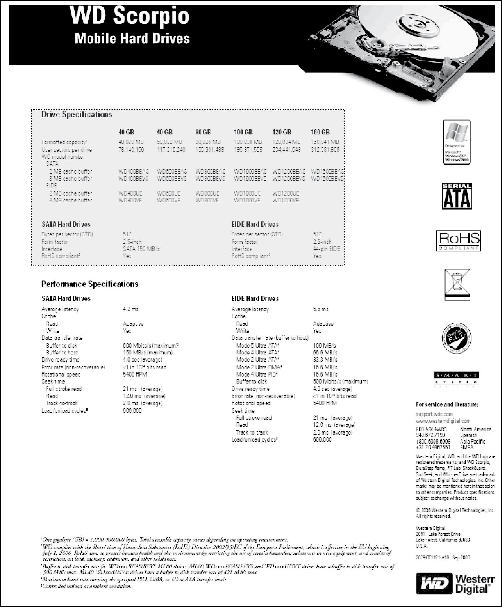
2.2.1 Example of Hard Disk Hardware
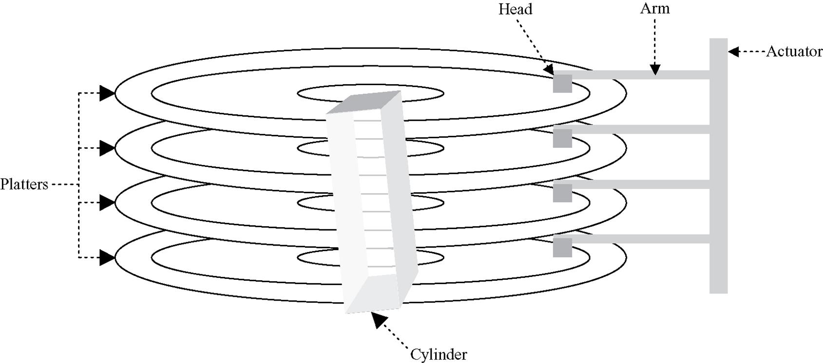
While there are several different types of hard disk technologies on the market today, such as SCSI (Small Computer Systems Interface) and ATA (Advanced Technology Attachment) types of hard disk drives to name a few, in general many internals of traditional hard disks deployed today are similar. As shown in Figure 2.5a, most hard drives on the market are made up of platters, circular disks made from metal and covered with a magnetic material. This film of magnetic material is one of the main components that allows data to be recorded on a hard disk’s platter. A hard disk’s head is a type of electromagnet to process the data located on the associated platter. An arm supports each head, and the arm(s) is (are) attached to an actuator which is responsible for arm and head movement to the desired location on a platter to process data. The number of platters, associated heads, and arms in a hard drive is dependent on the size of the hard disk, meaning the larger the drive the more platters, associated heads, and arms exist.

A low-level format (LLF) creates tracks, cylinders, and sectors on each platter (see Figure 2.5b). An LLF is performed on most modern hard disks by the manufacturer before the hard disks are deployed into the field. Some hard drive manufacturers also provide tools to do an LLF in cases where everything needs to be removed from a hard disk without damage to the boot sector, such as when installing a new operating system or removing virus infection.
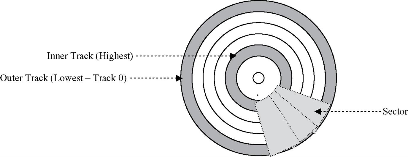
Tracks are concentric rings located on each platter that subdivide a platter for data recording. As shown in Figure 2.5c, a cylinder is a logical cross-section of tracks across all the hard disk’s platters. Tracks are further broken down into sectors, which are data blocks on a platter that allow for simultaneous access to multiple tracks for data processing. Accessing a data block on a hard disk is done via specifying the CHS, cylinder, head, and sector numbers.
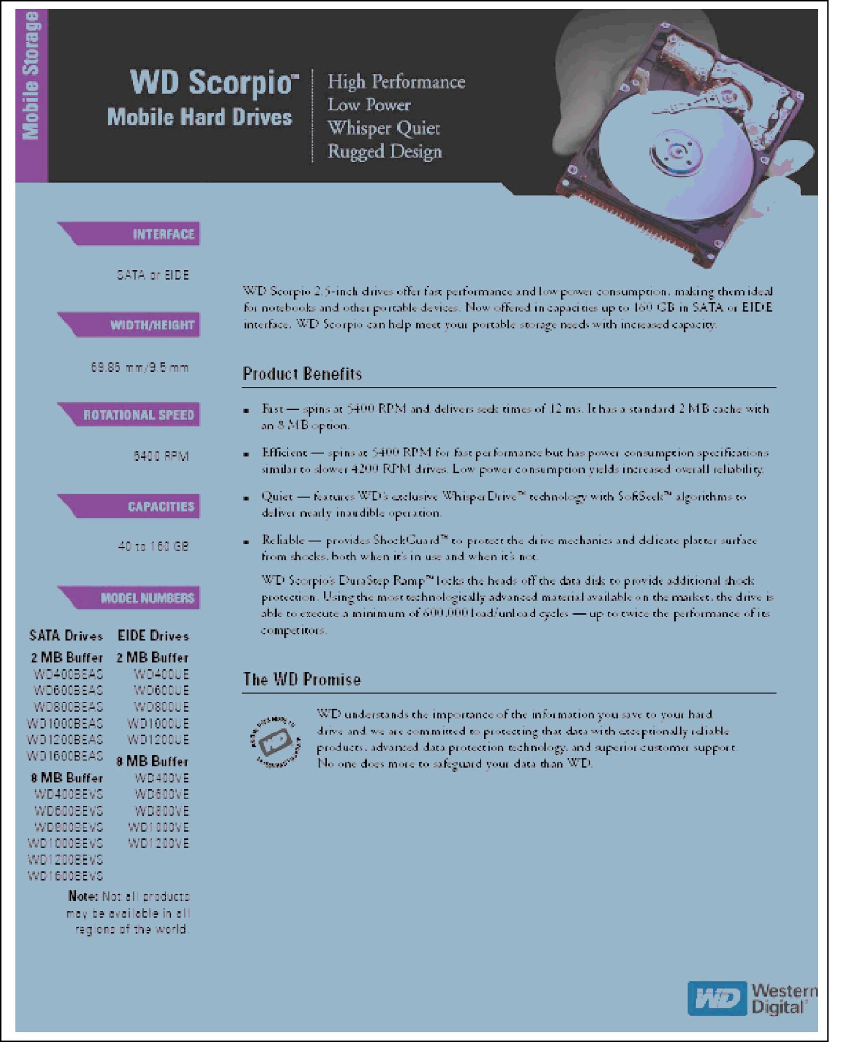
Refer to a hard disk manufacturer’s datasheet to determine detailed information of a particular hard disk’s specifications. The real-world hard disk datasheets shown in Figures 2.6a and 2.6b are examples of how to find some of the hardware specification information that is useful for developers to know regarding hard disks (see highlighted portions of datasheets).


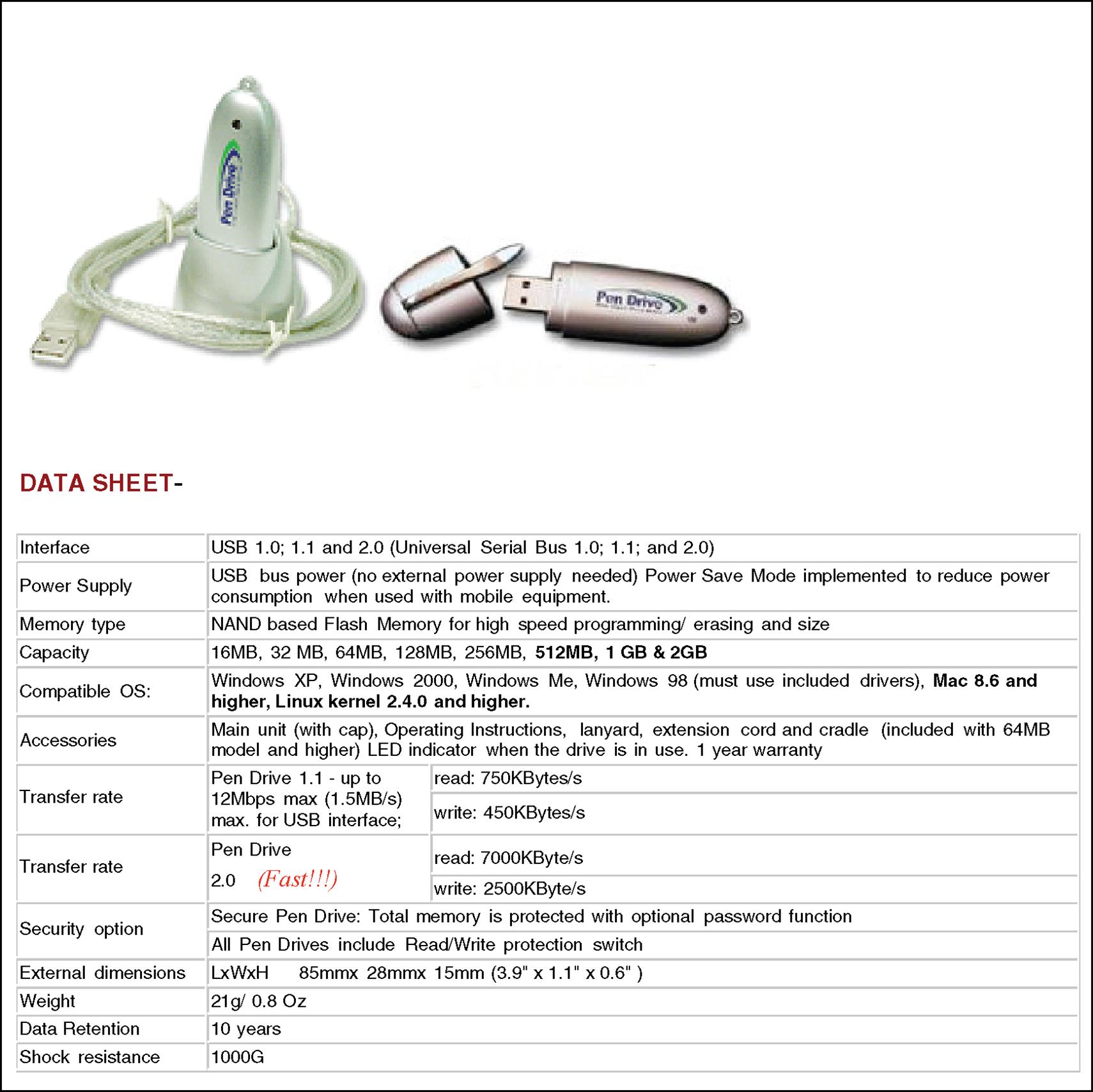
2.2.2 Example of USB Flash Memory
USB flash memory is simply a data storage device that contains non-volatile flash memory and an integrated USB interface. Relative to middleware, some of the key features of interest regarding USB Flash memory include:
• Capacity. The size of the USB flash memory.
• Operating System (Device Driver) Support. What operating system distributions include device drivers for the USB Flash memory. If the embedded system’s operating system is not on that list, then a device driver will need to be created/ported and integrated.
• Formatted. Does the USB Flash memory come pre-formatted, in support of a particular file system, for example. The USB Flash memory may need to be erased and reprogrammed, as necessary, in support of a particular middleware.
• Sector Size. The smallest block of Flash that can be erased and/or programmed. The reader should also note whether there are any restrictions when reading the Flash.
As shown in Figure 2.7a, USB Flash memory is a small PCB (printed circuit board) that is enclosed in a durable chassis, and is powered via the connection to the embedded system’s USB port. A standard USB interface that adheres to the industry standard USB specification, such as USB 1.1 or USB 2.0, extends from this small chassis that allows the stick to be plugged into a board’s USB drive port as shown in Figure 2.7b. This device is typically smaller than other portable storage mediums, and is hot-swappable into a board’s USB port that has device driver support for the particular type of USB Flash memory.

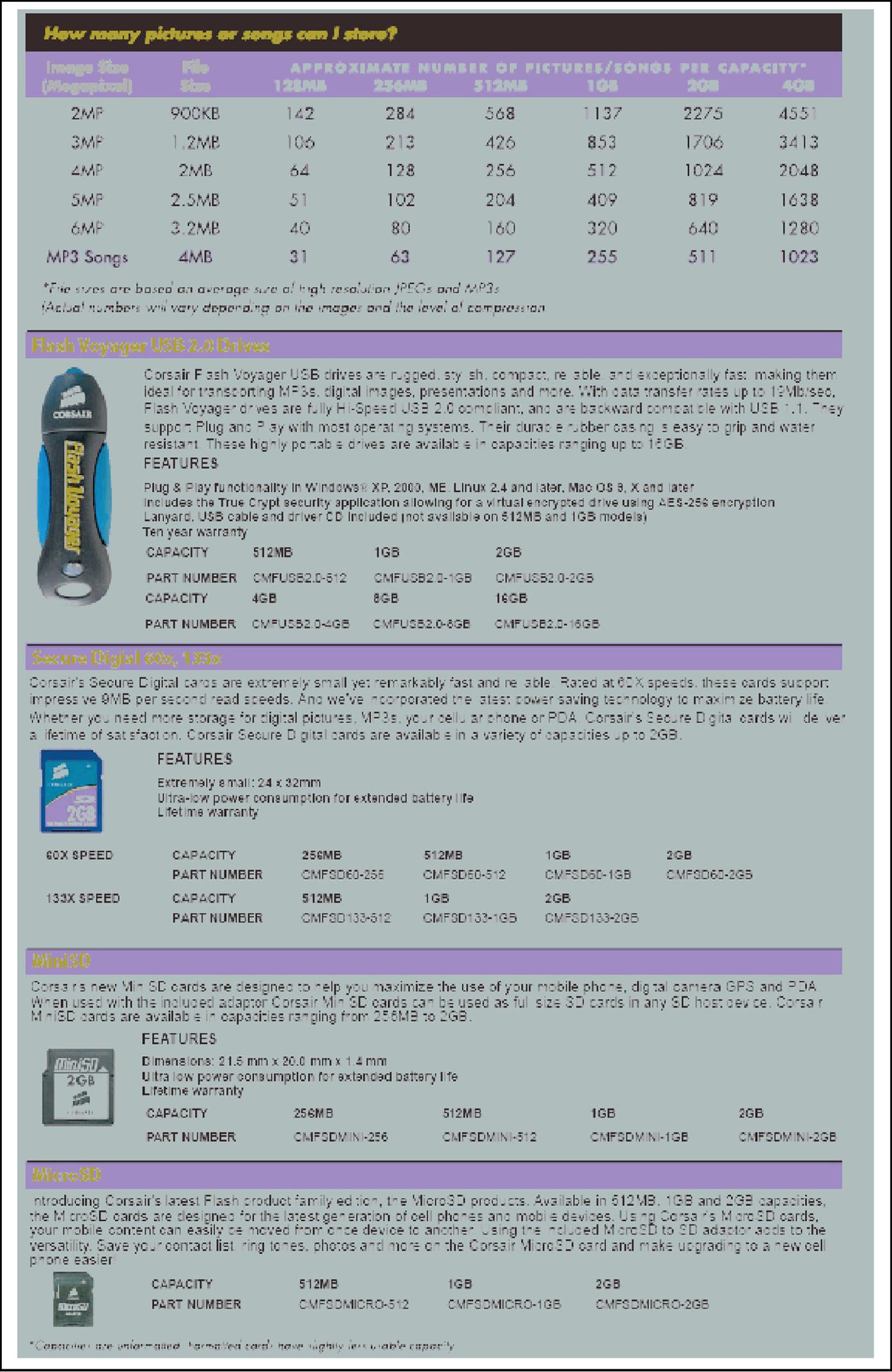
The real-world USB Flash memory datasheets shown in Figures 2.8a and 2.8b show some additional flash specification information that is useful for programmers to know regarding support of Flash types of storage mediums (see highlighted portions of datasheets).
2.3 Device Drivers and Middleware
Software that directly interfaces with the hardware in an embedded system is commonly referred to as a device driver. With some embedded operating systems that provide device drivers with their distributions, particular storage-medium-specific drivers can be referred to by other names, such as some Flash driver codes can be commonly referred to as MTDs (memory technology drivers). In the case of Flash, for example, MTDs are device drivers responsible for low-level mapping, reading, writing, and erasing of Flash. In short, as shown in Figure 2.9a, device drivers – including MTDs or whatever the particular device driver libraries are called in a distribution – manage the hardware and act as the interface to the hardware for higher layers of software.
For any embedded system that requires software, including higher-level software access to the hardware, these devices all have some type of device driver library. What is very important to remember as a programmer when trying to understand middleware support for a particular storage medium and its associated device driver library is that:
1. Different types of storage mediums will have different device driver requirements that need to be met
2. Even the same type of storage medium, such as USB Flash memory, that is created by different manufacturers can require different device drivers in support.
The reader must always check the details about the particular hardware if the part is not 100% identical to what is currently supported by the device, and not assume existing device drivers in the embedded system will be compatible for a particular storage medium part – even if the hardware is the same type of storage medium that the embedded device currently supports!
At a systems level, what specific middleware components exist and how they interface to the hardware will vary depending on the underlying device driver API for the particular storage medium(s). While, of course, libraries will vary between systems, in general hardware storage medium drivers will include some combination of:
• Storage Medium Installation, code that creates support of a storage medium in the embedded system
• Storage Medium Uninstall, code for removing the support of a storage medium in the embedded system
• Storage Medium Startup, initialization code for the storage medium upon reset and/or power-on
• Storage Medium Shutdown, termination code for the storage medium for entering into a power-off state
• Storage Medium Enable, code for enabling of the storage medium
• Storage Medium Disable, code for disabling the storage medium
• Storage Medium Acquire, code that provides other system software access to the storage medium
• Storage Medium Release, code that provides other system software the ability to free the storage medium
• Storage Medium Read, code that provides other system software the ability to read data from the storage medium
• Storage Medium Write, code that provides other system software the ability to write data to the storage medium
• Storage Medium Mapping, code for address mapping to and from the storage medium when reading, writing, and/or deleting data
• Storage Medium Unmapping, code for unmapping (removing) blocks of data in the storage medium.
Figures 2.9b, 2.9c and 2.9d are real-world examples of device driver APIs for Flash and ATA storage mediums that demonstrate the type of functionality introduced above and found in device driver libraries for these particular storage mediums. Later sections of this chapter will demonstrate examples of how these device drivers are utilized for implementing a middleware in an embedded device.
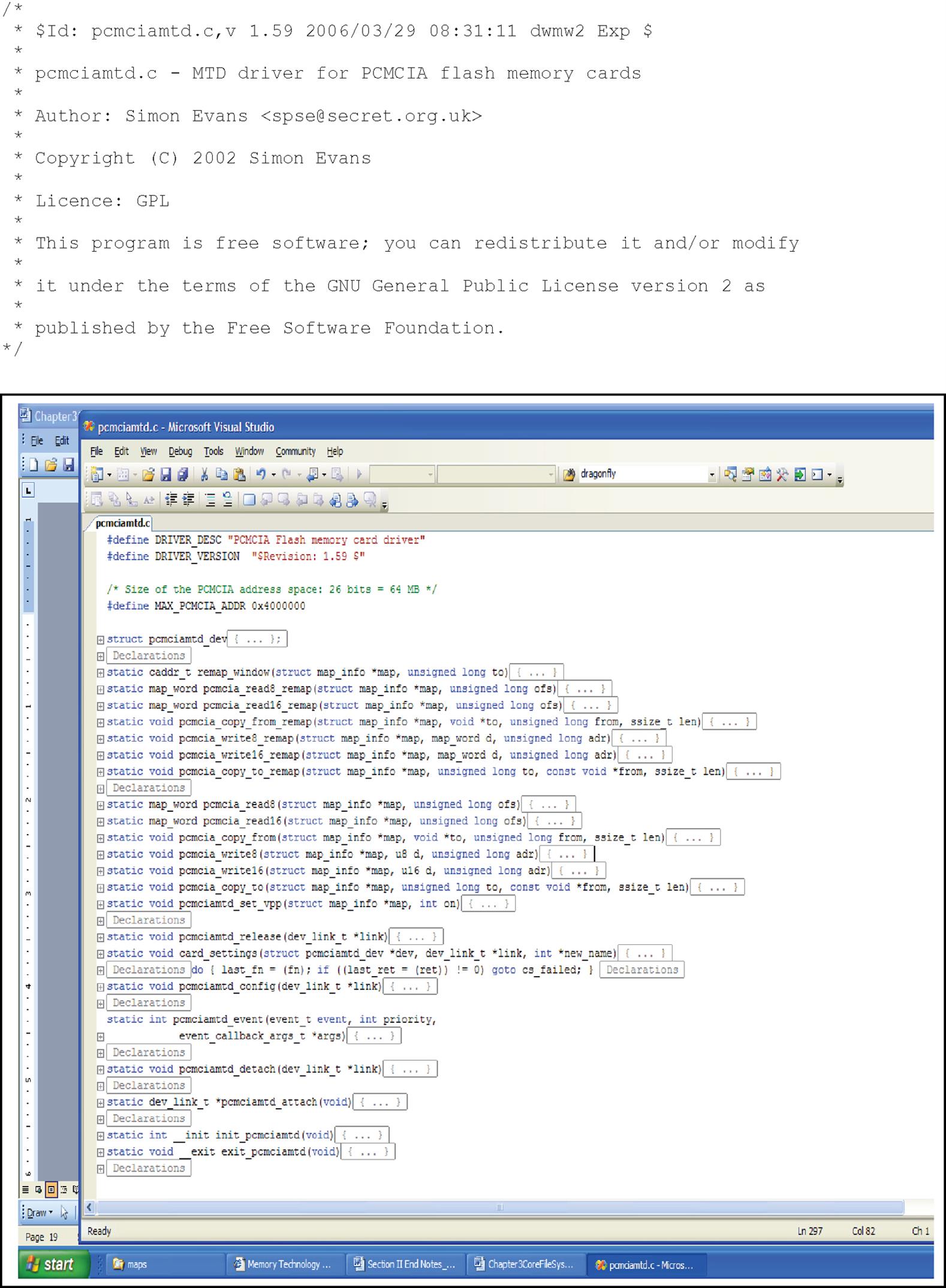


Note: please refer to the CD that accompanies this text or the Elsevier website link for this book (if no CD has been included) to see all open-source files for Linux Flash examples referenced in Figures 2.9b and 2.9c. Also, remember that the JFS implementation is just an open-source reference, and that to support a particular hardware platform requires updating and/or replacing the reference JFS device driver-specific calls with the required device driver-specific calls of a particular platform throughout the JFS source.
2.4 The Role of an Embedded System’s Operating System and Middleware-specific Code
The purpose of an embedded operating system is:
• to insure the embedded system operates in an efficient and reliable manner by managing hardware and software resources
• to provide an abstraction layer to simplify the process of developing higher layers of software
The embedded OS (operating system) achieves these functions via a kernel that includes, at a minimum: process management, memory management, and I/O system management components (Figure 2.10).
A kernel’s process management mechanisms are what provide the functionality that secures the illusion of simultaneous multitasking over a single processor. Kernel functionality that is relevant to middleware development ranges from task implementation to scheduling to synchronization to intertask communication. Middleware programmers need to note that embedded operating systems, and even different versions of the same embedded operating system, will vary widely in their process management schemes. For example, the types and number of operating system tasks:
• one type of task that implements one ‘thread of execution’ (task’s Program Counter)
• core OS vThreads based on vxWorks 5.5 multithreading, like vxWorks 6.4 one type
• OneshotTimer Task, task that is run only once
• PeriodicTimer Task, task that is run after a particular set time interval
• HarmonicEvent Task, task that runs alongside a periodic timer task
• JoinEvent Task, task that is set to run when an associated task completes
• InterruptEvent Task, task that is run when a hardware interrupt occurs
• UserEvent Task, task that is explicitly triggered by another task.
It comes down to balancing between utilizing the system’s resources (i.e., keeping the CPU, I/O, etc. as busy as possible) – with task throughput to process as many tasks as possible in a given amount of time – with fairness and ensuring that task starvation does not occur when trying to achieve a maximum task throughput. The key for developers to note relative to embedded operating systems is what impacts effectiveness and performance, and not to underestimate the impact of an embedded OS’s internal design. The key differentiators between embedded operating systems in this regard are:
1. Memory Management Scheme, i.e., virtual memory swapping scheme and page faults
2. Scheduling Scheme, i.e., throughput, execution time, and wait time
• Response time, to make the context switch to a ready task and waiting time of task in ready queue
• Turnaround time, how long a process takes to complete running
• Overhead, the time and data needed to determine which tasks will run next
• Fairness, what are the determining factors as to which processes get to run.
The key questions middleware developers need to ask of embedded OS support include: What hardware can this support? Are there any performance limitations? How about memory footprint? Middleware that resides on an OS needs an embedded OS that has been stably ported and is supporting the hardware.
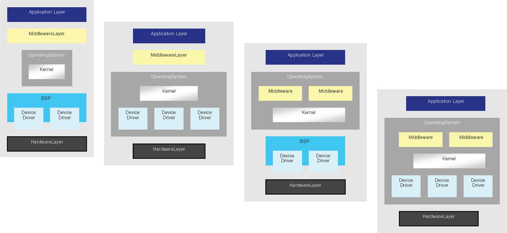
How about what features you need given cost, schedule, requirements, etc.? Do you just need a kernel or more? How scalable should the embedded OS be? This is because in addition to a kernel, embedded OS distributions may also provide additional integrated components, such as networking, file system, and database support. These components allow the overlying middleware layers to be ported to the OS kernel design, as well as the underlying system software and hardware (see examples in Figures 2.11a and 2.11b).

For example, a file system interface is some subset of OS functionality that can be utilized by the ported file system. When porting a file system to a different OS, it is important to understand what (if any) interfaces are available to the file system since the OS APIs available to a file system will vary from one OS to another, and what APIs a file system requires will differ from one file system implementation to another. For example, in Figure 2.11c, the JFS open-source file system provided on this textbook’s CD utilizes several different Linux-specific files (see source code on CD for complete overview of all required Linux APIs for JFS). To port JFS to an unsupported OS requires replacing the current OS-specific calls, such as the Linux-specific code shown in Figure 2.11c, with the new OS-specific file system interface calls throughout the JFS source.

2.5 Operating Systems and Device Driver Access for Middleware
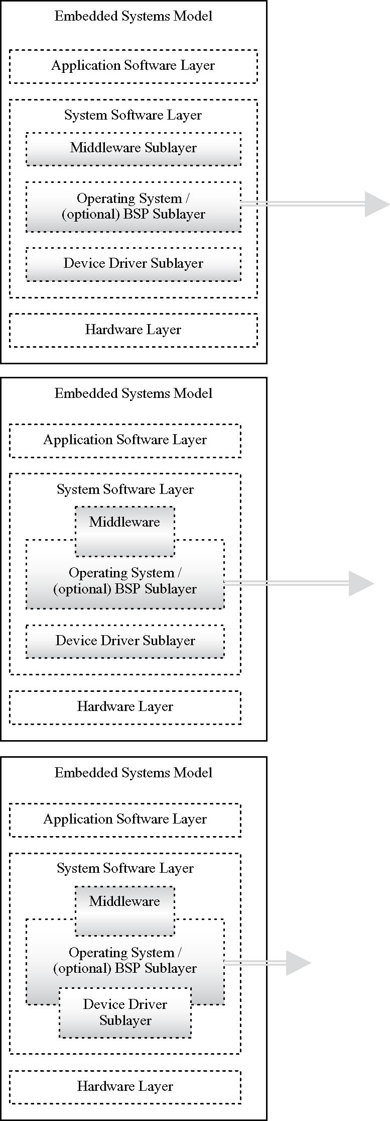
While middleware can access device drivers directly, as introduced in the previous section, an embedded OS can also include an abstraction layer API that allows for device driver access. When providing device access, or any type of I/O access to middleware, most OS APIs categorize their associated device drivers as some combination of:
• Character, a driver that allows hardware access via a (character) byte stream
• Block, a driver that allows hardware access via some smallest addressable set of bytes at any given time
• Network, a driver that allows hardware access via data in the form of networking packets
• Virtual, a driver that allows I/O access to virtual (software) devices
• Miscellaneous Monitor and Control, a driver that allows I/O access to hardware that is not accessible via the other categories above.
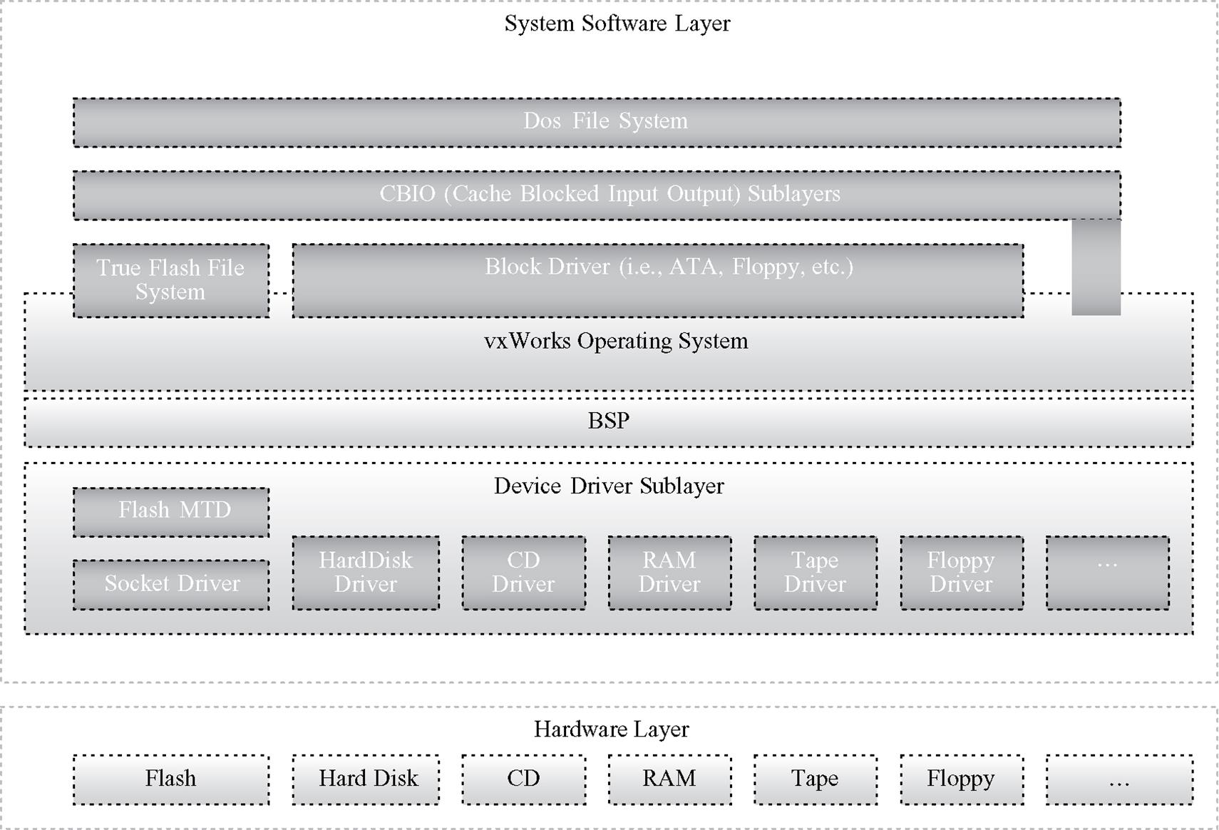
For an example of an OS block device interface, vxWorks provides an I/O interface, called CBIO (cache blocked input output), that allows different file systems, such as JFS, dosFS, etc., to be ported to one standard vxWorks interface regardless of the underlying hardware storage medium (see Figures 2.11d and 2.11e). As stated in the previous section, to port JFS to an unsupported OS, such as vxWorks in this case, requires replacing the current OS-specific calls, such as the Linux-specific code shown in Figure 2.11c, with the vxWorks specific code and utilizing the CBIO library throughout the JFS source.
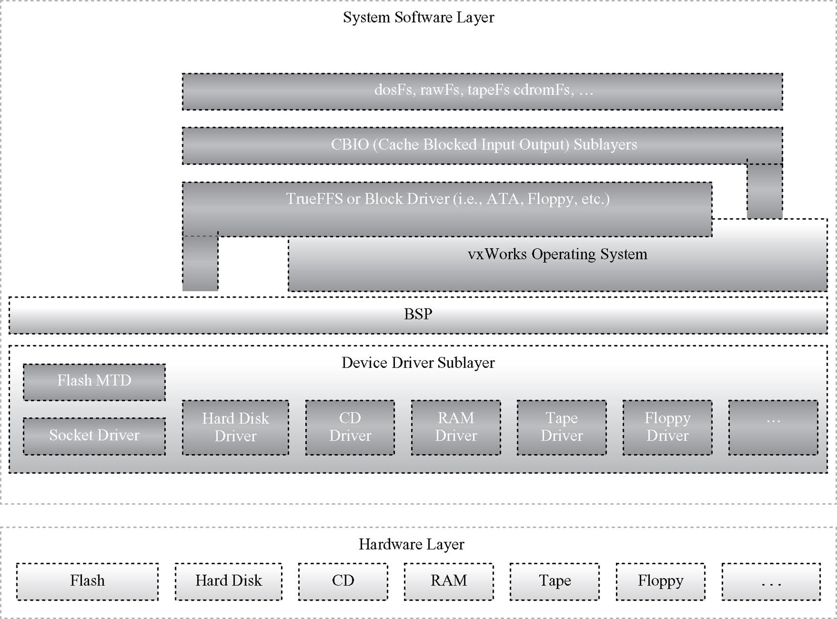
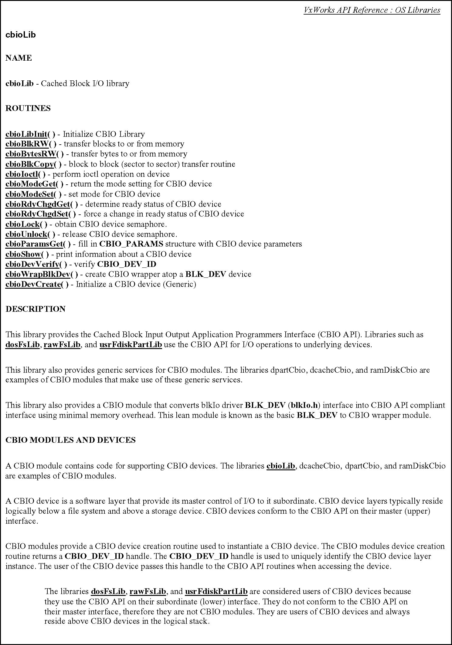
In vxWorks, calling some of the CBIO APIs is part of the process of setting up a file system, such as dosFS on a hard disk, floppy drive or any other storage medium accessed as a block device under vxWorks.
As shown in Figure 2.11f, when utilizing the CBIO APIs in vxWorks an example process is as follows:

Step 1. Configure vxWorks to support the:


Step 2. Create the Block Device.

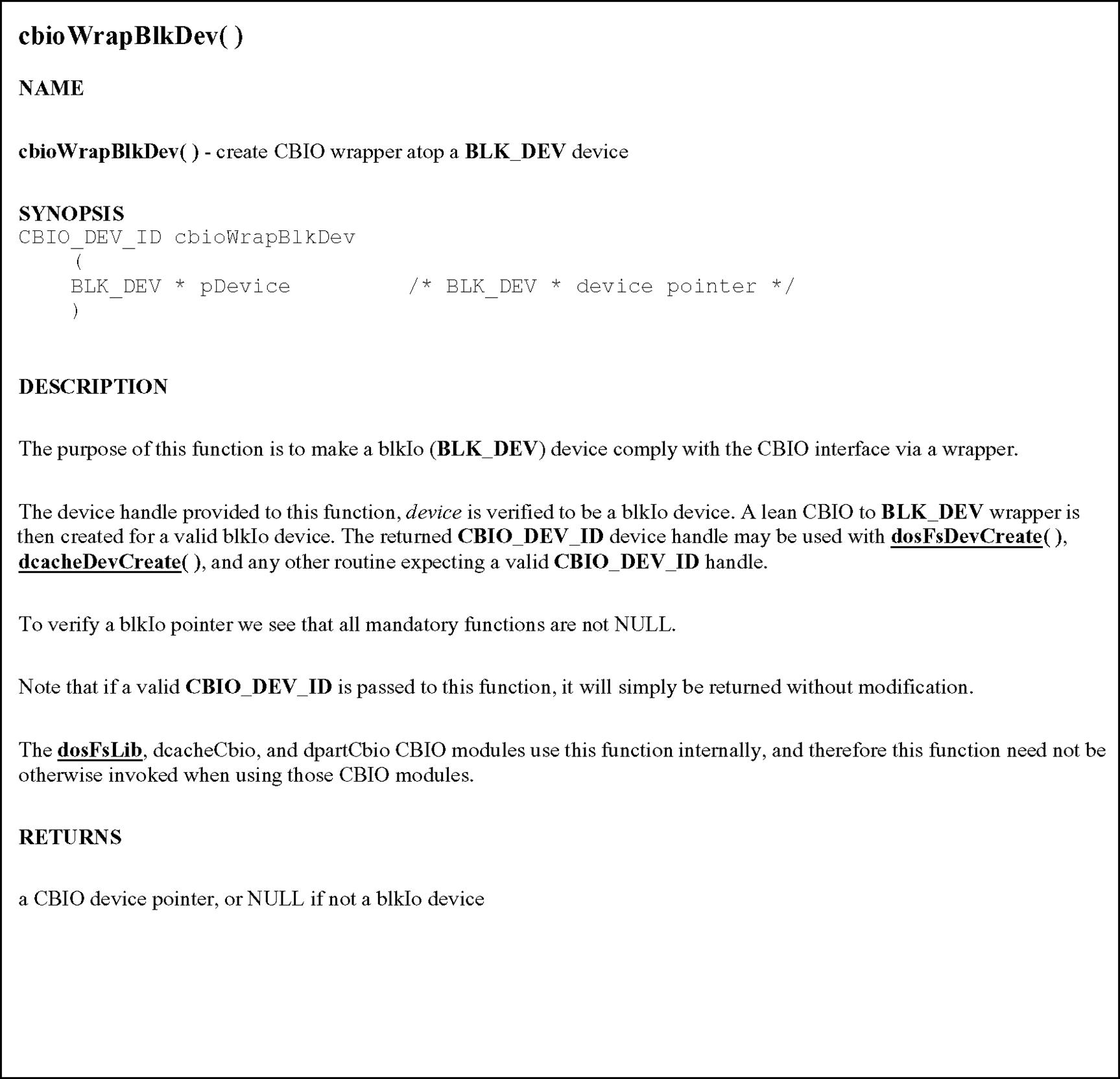
Step 3. Create the CBIO Block Driver Wrapper. The CBIO block driver wrapper layer wraps the block driver with a CBIO API compatible layer using the cbioWrapBlkDev() function.
Step 4. Create the CBIO Cache Layer

.
Step 5. Implement CBIO Partition Manager.

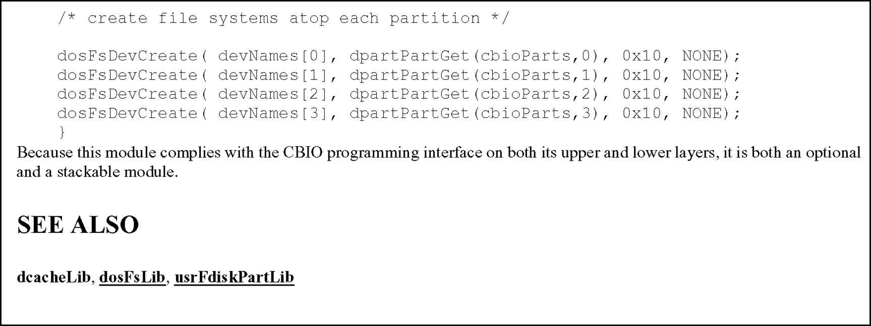
An example of source code using the CBIO APIs in vxWorks is shown in Figure 2.11l.
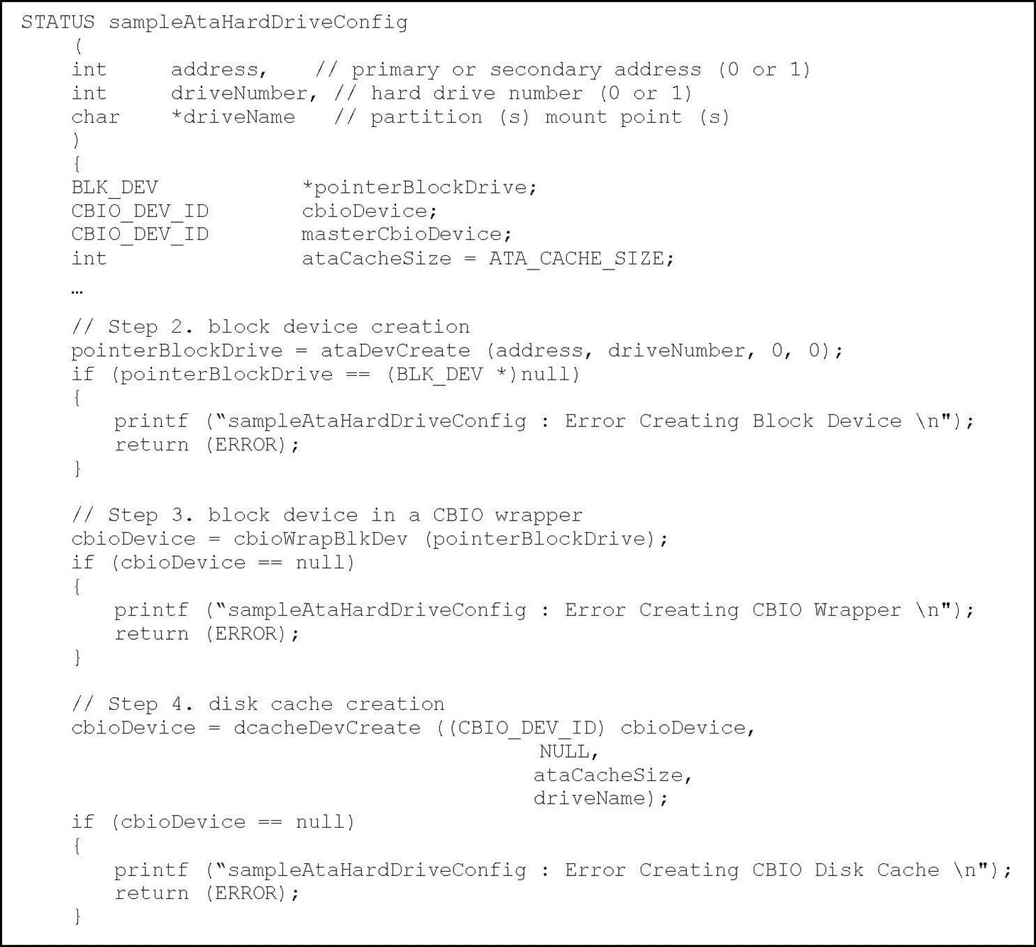

2.6 A Brief Comment on Multiple Middleware Components
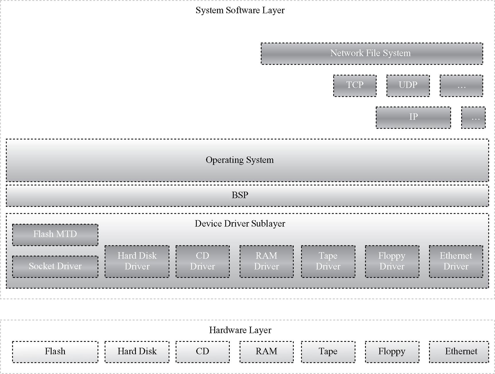
There is middleware that requires other middleware components in the embedded device in order to function. In the case of a network file system, for example, since it is a file system scheme that allows for access to files, a.k.a. file sharing, across networked computer systems it requires compatible, underlying networking protocols in support of file management and transmission (see Figure 2.12a).
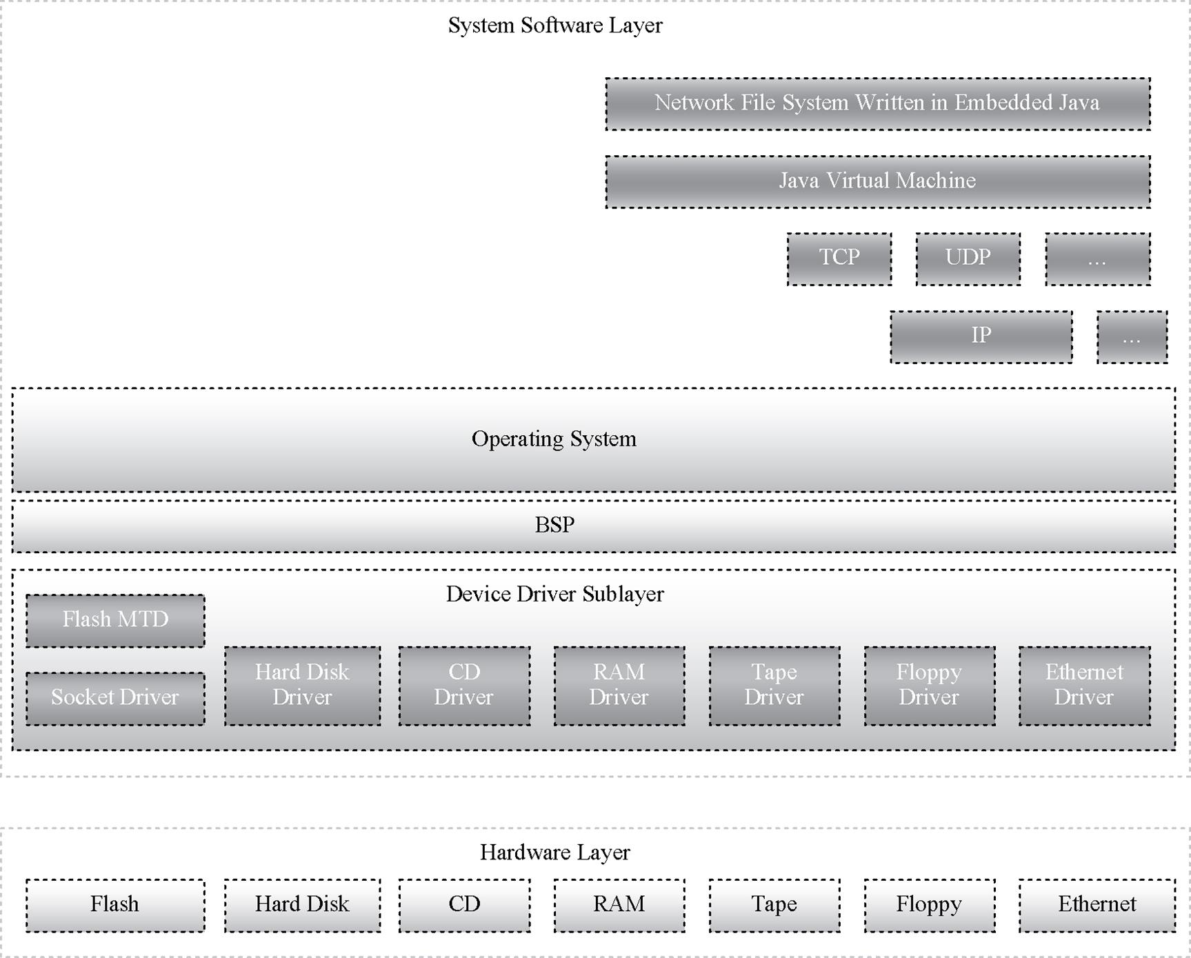
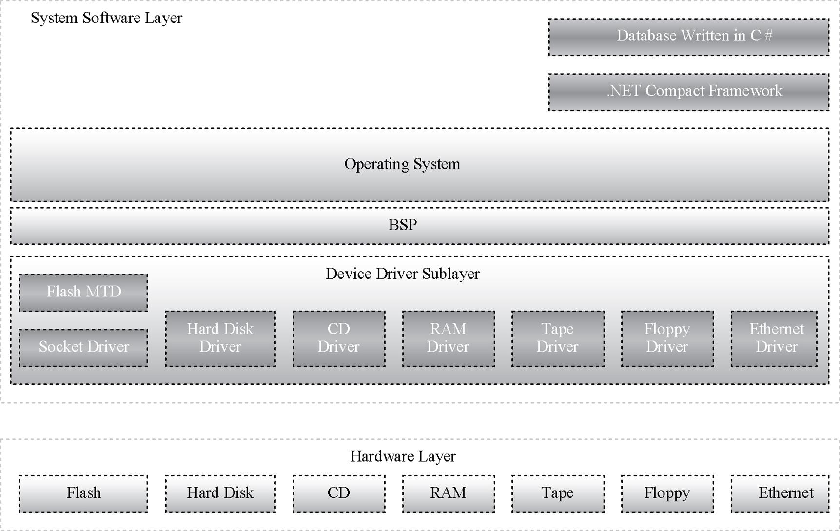
Another example, shown in Figures 2.12b and 2.12c, is in the instance in which some type of virtual machine is integrated in the system software in support middleware, such as a database or file system, written in a non-native language such as C# or Java. Refer to the chapter discussing the particular middleware components in these examples for more information.
2.7 Summary
In order to understand a particular middleware design, to determine which middleware design is the right choice for an embedded device, as well as understand the impact of middleware software on a particular device, it is important to first understand the foundation that underlies the middleware. This foundation includes some combination of the hardware, as well as device drivers, operating systems, and other required middleware components. The reader can then apply these fundamentals to analyzing what would be required to get a particular middleware component running in an embedded system, to determine which middleware design is the right one for a particular system, as well as the impact of the file system on the embedded device.
Chapter 3 introduces middleware standards and the importance of these standards within the context of any design.
2.8 Problems
1. Name three underlying components that could act as a foundation to an embedded system with middleware. Draw an example.
2. Middleware can reside directly over device driver software (True/False).
3. Why is it important for middleware programmers to understand the hardware of an embedded system?
4. One or more middleware component can be implemented in an embedded system (True/False).
5. How does middleware view the hardware storage medium? Draw an example.
6. Middleware can manage data on the following hardware:
7. List and describe six types of device driver API functionality typically found in hardware storage medium device drivers.
8. What is the difference between an operating system character device and a block device?
9. Middleware never requires other underlying middleware components (True/False).
10. Draw a high-level diagram of a type of middleware that requires a Java Virtual Machine (JVM).
2.9 End Notes
1Microsoft Extensible Firmware Initiative FAT32 File System Specification. Version 1.03, December 6, 2000. Microsoft Corporation.
2http://redhat.brandfuelstores.com/.
5‘Embedded Systems Architecture: A Comprehensive Guide for Engineers and Programmers’. T. Noergaard. Elsevier 2005, p. 245.
6http://www.westerndigital.com/en/products/Products.asp?DriveID=104
7http://www.seagate.com/cda/products/discsales/marketing/detail/0,1081,771,00.html
8http://www.babyusb.com/flashspecs2.htm
9‘XScale Lite Datasheet’ RLC Enterprises, Inc.
10http://www.psism.com/pendrive.htm
11‘Corsair USB Flash Memory Datasheet’. Corsair.
12http://www.linux-mtd.infradead.org/archive/
13‘vxWorks API Reference Guide : Device Drivers’. Version 5.5.
14National Semiconductor, ‘Geode User Manual,’ Rev. 1, p. 13.
15Net Silicon, ‘Net + ARM40 Hardware Reference Guide,’ pp. 1–5.
16‘EnCore M3 Embedded Processor Reference Manual,’ Revision A, p. 8.
17‘EnCore PP1 Embedded Processor Reference Manual,’ Revision A, p. 9.