Describe the Problem
I need to design a program that will allow the expert system to open and read a model containing the geometry of a part that I want to analyze and then to generate the commands for the numerically controlled (NC) machine to build the piece of sheet metal.
I am only concerned about sheet metal parts in this example. However, the CAD/CAM system can handle many other kinds of parts.
At a high level, I want the system to perform the following steps:
-
Analyze pieces of sheet metal.
-
See how they should be made, based on the features they contain.
-
Generate a set of instructions that are readable by manufacturing equipment. This set of instructions is called an NC set or a numerical control set.
-
Give these instructions to manufacturing equipment when I want to make any of these parts
The difficulty with my programming task is that I cannot simply extract the features from the dataset and generate NC set commands. The type of commands to use and the order of these commands depend upon the features and their relation to other features.
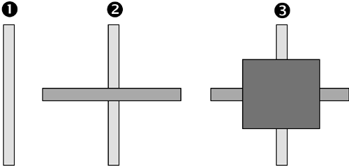
For example, take a shape that is made up of several features: a shape made up of a cutout with two slots. One of the slots runs vertically through the cutout while the other runs horizontally through it. This is shown in Figure 3-2.
Figure 3-2. A cutout with two slots. Left: How the part looks when finished. Right: It is really composed of three features.

It is important to realize that I am actually given the three features on the right to make up the shape on the left. That is because the engineers using the CAD/CAM system typically think in terms of the features to make up more complex shapes because they know that doing so will enable quicker manufacturing of the parts.
The problem is, I cannot just generate the NC set commands for the three features independently of one another and hope the part comes out properly—there is often a particular order that must be used. In the example, if I do the slots first and then the cutout, as shown in Figure 3-3, when the cutout is made (remember a cutout is created by using a high-impact punch), the sheet metal will bend because the slots will have weakened the metal.
Figure 3-3. A bad approach to cutting out the openings. This sequence results in weakened, bent sheet metal.

I must create the shape shown in Figure 3-2 by punching out the cutout first, then doing the slots. This works because the slots are created using a router, which applies sideways pressure. Making the cutout first actually makes the job easier, not harder. This is shown in Figure 3-4.
Figure 3-4. An expert's approach to cutting out the openings. This approach results in correct cutouts.

Fortunately, someone had already worked out the rules for the expert system. I did not have to worry about that. I took the time to explain these challenges so that you could understand the type of information needed by the expert system.
