The Essential Challenges and Approaches
The CAD/CAM system is constantly evolving, changing. My real problem was to make it possible for the company to continue to use its expensive expert system while the CAD/CAM system changed.
In my situation, they were currently using one version of the CAD/CAM system, Version 1 (V1), and a new version, Version 2 (V2), was coming out shortly. Although one vendor made both versions, the two versions were not compatible.
For a variety of technical and administrative reasons, it was not possible to translate the models from one version to the next. Thus, the expert system needed to be able to support both versions of the CAD/CAM system.
In fact, the situation was even a little worse than just having to accomodate two different versions of the CAD/CAM system. I knew a third version was coming out before long, but did not know when that would happen. In order to preserve the investment in the company's expert system, I wanted a system architecture approximately like the one diagrammed in Figure 3-5.
Figure 3-5. High-level view of my solution.

In other words, the application can initalize everything so that the expert system uses the appropriate CAD/CAM system. However, the expert system has to be able to use either version. Hence, I need to make V1 and V2 look the same to the expert system.
Although polymorphism is definitely needed at the geometry extractor level, it will not be needed at the feature level. This is because the expert system needs to know what type of features it is dealing with. However, we don't want to make any changes to the expert system when Version 3 of the CAD/CAM system comes out.
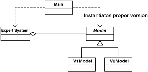
A basic understanding of object-oriented design implies that I will have a high-level class diagram similar to the one shown in Figure 3-6.
Figure 3-6. Class diagram of my solution.[1]

[1] This and all other class diagrams in this book use the Unified Modeling Language (UML) notation. See Chapter 2, “The UML—The Unified Modeling Language” for a description of UML notation.
In other words, the expert system relates to the CAD/CAM systems through the Model class. The Main class takes care of instantiating the correct version of the Model (that is, V1Model or V2Model).
Now, I will describe the CAD/CAM systems and how they work. Unfortunately, the two are very different beasts.
Version 1 is essentially a collection of subroutine libraries. To get information from a model, a series of calls must be made. A typical set of queries would be the following:
| Step | Do this in CAD/CAM Version 1 |
|---|---|
| 1. | Open model XYZ and return a handle to it |
| 2. | Store this handle as H |
| 3. | For model, referred to by H, tell me how many features are present, store as N |
| 4. | For each feature in the model referred to by H (from 1 to N) |
| 4a. | for model referred to by H, tell me the ID of the ith element and store as ID |
| 4b. | for model referred to by H, tell me the feature type of ID and store as T |
| 4c. | for model referred to by H, tell me the X coordinate of ID and store as X (use T to determine the proper routine to call, based on type) |
| … | … |
This system is painful to deal with and clearly not object-oriented. Whoever is using the system must maintain the context for every query manually. Each call about a feature must know what kind of feature it has.
The CAD/CAM vendor realized the inherent limitations of this type of system. The primary motivation for building V2 was to make it object-oriented. The geometry in V2 is therefore stored in objects. When a system requests a model, it gets back an object which represents the model. This model object contains a set of objects, each representing a feature. Since the problem domain is based on features, it is not surprising that the classes V2 uses to represent these features correspond exactly to the ones I have mentioned already: slots, holes, cutouts, specials, and irregulars.
Therefore, in V2, I can get a set of objects that correspond to the features that exist in the sheet metal. The UML diagram in Figure 3-7 shows the classes for the features.
Figure 3-7. Feature classes of V2.

The OOG stands for object-oriented geometry, just as a reminder that V2 is an object-oriented system.
