
10
Sandwich Structure
A sandwich structure (Figure 10.1) typically consists of two facesheets separated by lightweight core. Usually, the facesheets are bonded to the core with the use of adhesive but, under certain circumstances (for example, using X-cor® or K-cor® [1, 2]), it is possible to eliminate the use of adhesive.
Figure 10.1 Sandwich configuration

Composite laminates make up the facesheets. There is a variety of materials and configurations used for the core depending on the application and the desired properties: foam, honeycomb, low-density foaming aluminium, etc. Most core materials, in particular honeycombs, are anisotropic. They have different stiffnesses and strengths in different directions. In general, the purpose of the core is to increase the bending stiffness of the sandwich by moving material away from the neutral axis of the cross-section. The stiffness (and strength) of the core are, typically, much lower than those of the facesheets. As a result, for general loading situations such as that shown in Figure 10.1, with applied bending moment M and in-plane axial and shear loads N and V, respectively, all the load is taken by the facesheets. The bending moment (per unit width) is resolved into a force couple where one facesheet is loaded by a positive force per unit width Nm and the other by an equal and opposite force per unit width −Nm. The magnitude of that force is such that the force couple generates a moment equal to M:

The axial load N and the shear load V are divided equally between the two facesheets.
The core must still have minimum strength and stiffness in certain directions so that
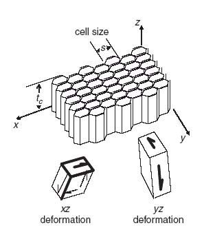
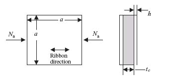
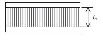
With reference to Figure 10.2, aside from the core thickness tc which determines the overall bending stiffnesses of the sandwich, the most important core properties are the transverse shear stiffnesses Gxz and Gyz, the corresponding transverse shear strengths Zxz and Zyz, the out-of-plane Young's modulus Ec and the corresponding (flatwise) tension and compression strengths Zt and Zc, respectively. Finally, for the case of honeycomb core such as that shown in Figure 10.2, the core cell size s plays a role in some of the failure modes. A thorough investigation of sandwich structures with isotropic facesheets can be found in reference [3].
Figure 10.2 Honeycomb core geometry
10.1 Sandwich Bending Stiffnesses
A sandwich can be treated as a laminate where the core is just another ply with negligible stiffness and strength properties and thickness equal to the core thickness. Standard classical laminated-plate theory (see Section 3.3) can be used to determine the corresponding A, B and D matrices. The presence of the core does not change the A matrix, but will affect the B (if the total layup is asymmetric) and D matrices significantly. This can be seen by applying Equation (8.14) to obtain the D matrix of a sandwich. Rewriting Equation (8.14) it can be shown that for a sandwich with identical facesheets

where the multiplicative factors of 2 appearing in the right-hand side account for the presence of two facesheets. The first term in the right-hand side of Equation (10.1) is the same as the EI term in Equation (8.14) with the stiffness E incorporated in the corresponding Dij term. The second term is the product of the stiffness and the distance from the neutral axis present in Equation (8.14) with the modulus this time lumped in the Aij term.
To see the effect of the core on increasing the bending stiffness of a sandwich, consider two facesheets of layup (±45)/(0/90)/(±45) separated by a core of varying core thickness. The individual A and D matrices for each facesheet are given by

Using Equation (10.1), the ratio of D11 for the entire sandwich divided by D11 for each facesheet can be determined as a function of varying core thickness. The result is shown in Figure 10.3.
Figure 10.3 Variation of sandwich bending stiffness as a function of core thickness
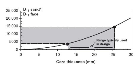
It can be seen from Figure 10.3 that even very small core thicknesses (5 mm) result in a 1000-fold increase of the bending stiffness. The range of typical core thicknesses used in many applications is also shown in Figure 10.3, indicating that, for such applications, the core increases the bending stiffness anywhere between 4000 and 15, 000 times.
This kind of improvement at a relatively small increase in weight, due to the presence of the core and adhesive, makes sandwich structure ideal for many stability-driven applications where high buckling loads are important. In fact, judicious selection of facesheet material and layup and core material and thickness would result in sandwich being the most weight-efficient structure if it were not for a variety of new failure modes associated with such configurations. Each of the components, facesheet, adhesive or core, can fail and there are more than one failure modes for each component. Some of these failure modes are quite limiting and tend to drive the design. The result is that sandwich is not always more efficient than the alternative(s) such as a skin-stiffened structure. It depends on the geometry, loading and design philosophy (e.g. whether post-buckling is allowed and at how high a post-buckling ratio). The most important of these failure modes are examined in subsequent sections.
In addition, it should be pointed out that in many applications where sandwich is selected, ramp-downs are used at the edges of the sandwich for attachment to adjacent structure. Ramp-downs are briefly discussed in Section 10.6.1. They tend to increase cost and introduce additional failure modes that must be checked to make sure they do not lead to premature failure of the entire structure.
10.2 Buckling of Sandwich Structure
Buckling is one of the critical failure modes for sandwich structure in particular for relatively large panels. The reason is that it is hard to design against all possible failure modes in the post-buckling regime and, as a result, buckling is usually considered to coincide with final failure.
10.2.1 Buckling of Sandwich under Compression
The procedure to determine the buckling load of a sandwich structure is very similar to that presented in Chapter 6 for monolithic laminates, with one important difference. The presence of the core makes the effects of transverse shear very important. If they are not properly accounted for, the predicted buckling load is very unconservative (higher than the case where transverse shear effects are accounted for).
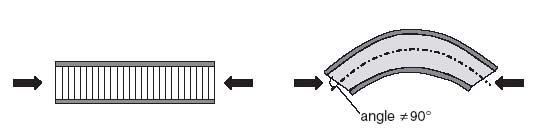
In a uniform thickness plate where transverse shear effects are significant the Kirchhoff hypothesis is no longer valid. Plane sections remain plane, but are no longer perpendicular to the plate mid-plane. This is shown schematically in Figure 10.4.
Figure 10.4 Bending of a sandwich panel under compression
The sandwich under compression is treated as a wide beam. Following the derivation in [4] for isotropic beams, the buckling load is given by

In Equation (10.2), NEcrit is the buckling load No of the sandwich if transverse shear effects are neglected, given, for simply supported edges, by Equation (6.7) repeated below for convenience:
(10.7) 
Also, tc and Gc are the core thickness and transverse shear stiffness, respectively. It is important to note that Gc is the value of the shear modulus (typically Gxz or Gyz) aligned with the loading direction.
Finally, k in Equation (10.2) is the shear correction factor. The shear correction factor is introduced to reconcile the inconsistency between the derived and assumed transverse shear stress distributions through the thickness of the plate. Engineering bending theory leads to a quadratic distribution of shear stress through the thickness while first-order shear deformation theory assumes the shear strain (and thus the shear stress) is independent of the through-thickness coordinate. This inconsistency [5] is reconciled by requiring that the work done following either formulation is the same. This leads to an expression for the transverse shear force (per unit width) of the form [5],
![]()
where the shear correction factor is k = 5/6 in this case, h is the plate thickness and γ is the transverse shear strain.
As mentioned earlier, most sandwich structures use core with very small shear stiffness Gxz compared with that of the facesheets. As a result, the shear stress through the thickness is very nearly uniform. This is consistent with the fact that bending stresses are not linearly distributed through the thickness of the core because, as was mentioned earlier, bending moments are transmitted through a sandwich as a force couple. Thus, there is (almost) no inconsistency between bending theory and first-order shear deformation theory and k ≈ 1. Thus,

An example would help illustrate the importance of transverse shear in a sandwich. The same facesheet properties as those in Section 10.1 and Figure 10.3 are used here. The core material is assumed to have a shear stiffness Gxz = 42.1 N/mm2. Equation (10.3) is used to calculate the buckling load of a square sandwich panel of side 508 mm and compare it with Equation (6.7), that is, without accounting for transverse shear. This is done for different core thicknesses and the results are shown in Figure 10.5.
Figure 10.5 Buckling load of a sandwich with and without transverse shear effects as a function of core thickness
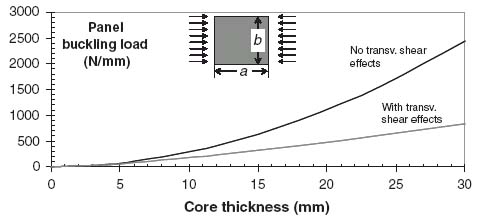
It can be seen that once the core thickness exceeds 5 mm, the buckling load including transverse shear effects diverges drastically from the buckling load without transverse shear effects. If transverse shear effects are included the buckling load is always lower. Even for a core thickness of 3 mm the two buckling loads (with and without transverse shear effects) differ by 21%.
10.2.2 Buckling of Sandwich under Shear
The situation is shown in Figure 10.6. The form of the equation predicting buckling of a simply supported sandwich under shear is the same as Equation (10.3):

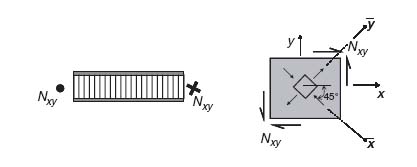
where Nxyc is the shear buckling load without transverse shear effects (see, e.g. Sections 6.3–6.5) and G45 is the core shear modulus in the 45° direction, as shown in Figure 10.6.
Figure 10.6 Sandwich panel under shear load

The shear modulus G45 is used because it is aligned with the primary load direction. Since a pure shear loading is equivalent to biaxial loading with tension in one direction and compression in the other (see, e.g. Section 7.2), the tendency for buckled half-waves to form is along the 45° line in Figure 10.6 (the direction of maximum compression) and G45, the core shear stiffness in that direction, opposes that tendency.
To determine G45 standard tensor transformation equations are used (Section 3.2, Equa-tion 3.8). The result is
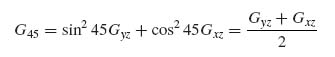
Using this result to substitute in Equation (10.4) and rearranging lead to
(10.6) 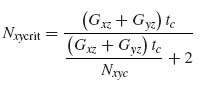
10.2.3 Buckling of Sandwich under Combined Loading
For combined loading situations the same interaction curves as those presented in Sections 6.5 and 6.6 can be used, provided the individual buckling loads are corrected for transverse shear effects as presented in the two previous sections.
10.3 Sandwich Wrinkling
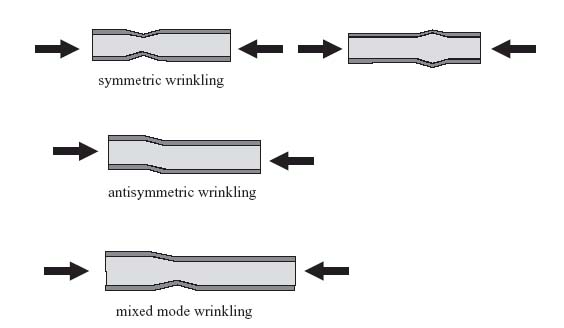
Wrinkling is a local buckling phenomenon where the facesheet of a sandwich buckles over a characteristic half-wavelength ![]() , which is unrelated to the overall length or width of the panel. There are three possible modes, symmetric, antisymmetric and mixed-mode wrinkling. These are shown schematically in Figure 10.7 for applied compression, but can also occur under applied shear or combined loads.
, which is unrelated to the overall length or width of the panel. There are three possible modes, symmetric, antisymmetric and mixed-mode wrinkling. These are shown schematically in Figure 10.7 for applied compression, but can also occur under applied shear or combined loads.
Figure 10.7 Sandwich wrinkling modes
10.3.1 Sandwich Wrinkling under Compression
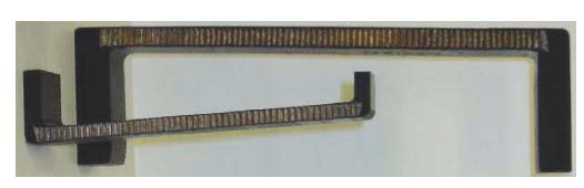
The symmetric wrinkling case is examined here in detail (see also [6]). A sandwich compression specimen, which failed in wrinkling, is shown in Figure 10.8.
Figure 10.8 Wrinkling failure of sandwich tested in compression

The deformed shape after the facesheet has buckled in the wrinkling mode is idealized in Figure 10.9. This shape extends through the width of the sandwich (perpendicular to the plane of Figure 10.9). It is assumed that the sandwich is very long in the y direction. It is also assumed that at the edges of the buckled shape, at x = 0 and x = ![]() , the boundary conditions on the facesheet are those of simple support, that is, w = 0 there.
, the boundary conditions on the facesheet are those of simple support, that is, w = 0 there.
Figure 10.9 Deformed configuration of sandwich undergoing symmetric wrinkling
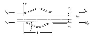
One important aspect of the formulation is modelling the behaviour of the core. Assuming perfect bonding between core and facesheet, it is obvious from Figure 10.9 that the core deforms under the buckled facesheet. In the case shown in Figure 10.9, the core extends in the z direction. If the core were very thick, there would be a region near the mid-plane of the core where the core would not deform. So the core deformations are confined in a region close to the facesheet. It is assumed that this region has width zc (Figure 10.9) where zc is unknown at this point. It is also assumed that the core deflections in the z direction vary linearly with z.
Combining the assumption of simply supported ends for the deformed facesheet and linear variation of deflection for the core, the following expression for w is introduced:
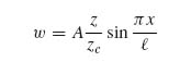
Equation (10.7) satisfies the requirement that w = 0 at x = 0 and x = ![]() . It also satisfies the linear variation of w as a function of z with w = 0 at z = 0 (i.e. at the interface where core deformations seize to be significant) and reproducing the facesheet sinusoidal deformation at z = zc, which is the intersection of the core with the facesheet.
. It also satisfies the linear variation of w as a function of z with w = 0 at z = 0 (i.e. at the interface where core deformations seize to be significant) and reproducing the facesheet sinusoidal deformation at z = zc, which is the intersection of the core with the facesheet.
The wrinkling load is determined by energy minimization. During wrinkling, energy is stored in bending the facesheet and extending the core. So the energy expression has the form
where Uf is the energy in each facesheet and Uc is the energy stored in the core. W is the work done by the applied load on one end of the sandwich. The factors of 2 in this equation account for the presence of two (identical) facesheets.
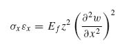
Neglecting deformations u and v in the plane of the facesheet, the strain and stress in the facesheet can be obtained from Equations (5.6), (5.7) and (5.4):
(10.9) ![]()
where Ef is the facesheet membrane modulus obtained from Equation (8.6).
Then,
Thus, the facesheet energy can be written as
(10.10) 
where ![]() is the moment of inertia of the facesheet per unit width b. It should be noted that this expression can also be obtained from Equation (5.62) assuming a symmetric facesheet and noticing that only the D11 term contributes with D11 = EI/b, where b is the width of the facesheet perpendicular to the plane of Figure 10.9.
is the moment of inertia of the facesheet per unit width b. It should be noted that this expression can also be obtained from Equation (5.62) assuming a symmetric facesheet and noticing that only the D11 term contributes with D11 = EI/b, where b is the width of the facesheet perpendicular to the plane of Figure 10.9.
The strain–displacement and stress–strain equations (5.9) and (5.4) applied to the core give
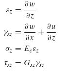
where Ec is the core modulus in the z direction and Gxz is the transverse shear modulus of the core for shearing in the xz plane (see Figure 10.9).
As already mentioned, the u deflection of the core is negligible. Then, the above equations can be combined to

which, in turn, can be substituted for in the core energy expression:
(10.11) 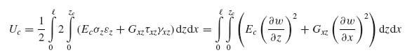
Note the factor of 2 in front of the second integral, which is introduced to account for the fact that there are two portions of the core (one above and one below the mid-plane) both of thickness zc that contribute to the core energy.
The external work done by the applied load Nx per facesheet per unit width is given by

with δ the deflection at the edge of the sandwich portion considered, that is, at x = 0 and x = ![]() .
.
Considering the deformed shape of the facesheet shown in Figure 10.10, the deflection δ can be calculated using Pythagoras' theorem and assuming small deflections w.
Figure 10.10 Deformed facesheet and local geometry

By Pythagoras' theorem,

The quantity involving the square root can be expanded into the first two terms of a Taylor series (valid for small (dw/ds)2) to give

and for small deflections w

Therefore, substituting in the expression for δ,

At this point, the relevant w derivatives present in the energy expression are evaluated

and substituted in Equation (10.8). Evaluating the integrals gives
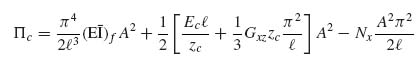
Equation (10.12) must be minimized with respect to the unknown amplitude A. This implies
(10.13) 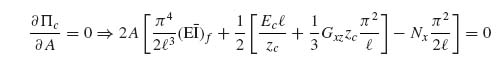
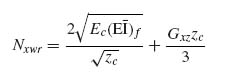
For nonzero values of A, the quantity in brackets must be zero. This gives a condition for the wrinkling load Nx. Denoting the wrinkling load by Nxwr:

Examining Equation (10.14) it can be seen that the first term of the right-hand side is the buckling load of a beam column (per unit width). The second term is the contribution to the buckling load of a beam by an elastic foundation when the stiffness of the foundation k equals Ec/zc. This can be readily seen by comparing this term with Equation (8.33) when m = 1. The third term is the contribution of the elastic foundation when it consists of torsional instead of extensional springs.
This expression for the wrinkling load is still in terms of two unknowns: ![]() the half-wavelength during wrinkling and zc the portion of the core undergoing deformations during wrinkling. Each of them is determined by noticing that if Nx starts increasing from zero, then wrinkling will occur at the lowest possible value that Equation (10.14) allows as a function of
the half-wavelength during wrinkling and zc the portion of the core undergoing deformations during wrinkling. Each of them is determined by noticing that if Nx starts increasing from zero, then wrinkling will occur at the lowest possible value that Equation (10.14) allows as a function of ![]() and zc. Therefore, minimizing Nxwr with respect to
and zc. Therefore, minimizing Nxwr with respect to ![]() gives:
gives:

which gives a condition relating ![]() and zc. Using it to eliminate
and zc. Using it to eliminate ![]() from Equation (10.14) results in
from Equation (10.14) results in
which is only in terms of zc. Differentiating now with respect to zc and setting the result equal to 0 gives

Now the moment of inertia per unit width

is used to substitute in Equation (10.17) to obtain the final expression for zc:

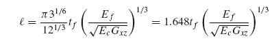
This expression can now be used to substitute in Equation (10.15) to get the final value for the half-wavelength:
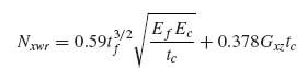
Finally, Equation (10.18) can be used to substitute in Equation (10.16) to obtain the wrinkling load
Equation (10.20) has been derived in many different ways [6, 7]. In fact, depending on the assumptions, the form of the equation remains the same and only the coefficient in the right-hand side changes [7].
It is important to keep in mind that the derivation so far has assumed that the core was sufficiently thick that the portion zc of the core undergoing deformations is less than or equal to half the core thickness tc/2. If zc given by Equation (10.18) is greater than half the core thickness, then the entire core deforms during wrinkling and

With this new value of zc new values of ![]() and Nxwr must be calculated. Following the same procedure as before, zc is substituted for in Equation (10.15) to get
and Nxwr must be calculated. Following the same procedure as before, zc is substituted for in Equation (10.15) to get

Then, the new value of zc is substituted in Equation (10.16) to obtain

The condition for the full depth of the core being involved in the wrinkling deformations can be obtained from Equation (10.18). If the right-hand side of Equation (10.18) is greater than tc/2, then the entire core thickness deforms. Therefore, if

the core deforms in its entirety, and Equations (10.18a), (10.19a) and (10.20a) are valid. Otherwise, only a portion zc of the core deforms and Equations (10.18), (10.19) and (10.20) are valid.
It should be noted that, according to Equation (10.20a), as the core thickness increases the wrinkling load decreases. So it would be expected that wrinkling would become the primary failure mode beyond a certain core thickness. However, this is only true as long as Equation (10.21) is satisfied. Once the core thickness exceeds the right-hand side of Equation (10.21) the governing equation is Equation (10.20), which is independent of the core thickness.
For antisymmetric wrinkling, an analogous approach to that presented above, but with a different expression for the w deflection of the core in order to satisfy the different boundary conditions, leads to the following results [6, 8]:
(10.22) ![]()
(10.23) 
(10.24) 
for sufficiently thick core, that is, when
(10.25) 
or when the entire core thickness undergoes deformations (core is relatively thin),
(10.23a) ![]()
valid when
(10.25a) 
In practice, one would have to evaluate both symmetric and antisymmetric wrinkling loads for a given application and use the lowest of the two. However, it can be demonstrated (see Exercise 10.1) that only for very thin cores is antisymmetric wrinkling possible. For typical core thicknesses, symmetric wrinkling is the mode of failure.
Comparison of the predictions for symmetric and antisymmetric wrinkling with experimental results is difficult to do with the equations presented so far. The main reason is that sandwich structure is most often fabricated by co-curing core, adhesive and facesheets all at once. As a result of this process the facesheets are not perfectly flat, but have some waviness. This waviness is not included in the analysis presented so far. Only if the facesheets are pre-cured separately and then bonded on a perfectly flat core will the waviness be (mostly) eliminated.
For this reason, the predictions presented so far are compared with finite element models in which the facesheets are perfectly flat. Such a comparison can be found in reference [9] and its conclusions are summarized here.
A sandwich with 25.4 mm honeycomb core and facesheets made with four plain weave fabric plies and layup [(±45)/(0/90)2/(±45)] was modelled under compression using finite elements. The facesheet stiffness Ef was 64 GPa. Since the core was thick, only symmetric wrinkling predictions were used. The pertinent core properties and a comparison or prediction from Equations (10.19) and (10.20) are shown in Table 10.1 for three different core materials with the same facesheet.
Table 10.1 Analytical predictions versus FE results for sandwich wrinkling

It can be seen that the predictions for the wrinkling stress Nxwr/tf and the corresponding half-wavelength ![]() are in good agreement with finite elements with the highest discrepancy being less than 20%. It should be noted that the predicted wrinkling loads are always less than the finite element result. Also, the greatest discrepancy in wrinkling stress (case 2) does not correspond to the case with the greatest discrepancy in the half-wavelength (case 3). The discrepancies are attributed to a combination of finite element modelling issues related to proper load introduction and boundary conditions, and to the fact that Equation (10.7) is an approximation, especially considering the assumed linear variation with out-of-plane coordinate z.
are in good agreement with finite elements with the highest discrepancy being less than 20%. It should be noted that the predicted wrinkling loads are always less than the finite element result. Also, the greatest discrepancy in wrinkling stress (case 2) does not correspond to the case with the greatest discrepancy in the half-wavelength (case 3). The discrepancies are attributed to a combination of finite element modelling issues related to proper load introduction and boundary conditions, and to the fact that Equation (10.7) is an approximation, especially considering the assumed linear variation with out-of-plane coordinate z.
The discussion so far has not explicitly accounted for the fact that the facesheets are made of composite materials. Only by substituting the appropriate value for the facesheet in-plane stiffness Ef in the equations derived does one account for composite laminates. For more accurate values for Ef in case of composite facesheets, the following expression can be used [7]:

where νxy, νyx and D11f are Poisson's ratios and bending stiffness of the facesheet.
Other models explicitly incorporating composite layups can be found in the literature. For example, symmetric wrinkling was determined by Pearce and Webber [10] as

Comparing Equation (10.27) with Equation (8.33) suggests that the wrinkling load consists of two parts, the buckling load of the facesheet and a contribution from the core acting as an elastic foundation with spring constant k = 2Ec/tc. Indeed, the first part of Equation (10.27) is identical to the buckling load of a simply supported plate under compression given by Equation (6.7). Finally, comparing Equation (10.27) with the wrinkling expression (10.14) derived earlier without explicitly incorporating the fact that the facesheet is composite, it is seen that the first two terms of Equation (10.14) have a one-to-one correspondence with the two terms of Equation (10.27). The first term corresponds to buckling of the facesheet and the second to the core acting as an elastic foundation and storing energy in deformation in the z direction. However, Equation (10.14) has an additional term dependent on the core shear stiffness which represents core shear deformations. This term is not present in Equa-tion (10.27). It is, therefore, expected that Equation (10.27) may not be as accurate when the core shear deformations are appreciable.
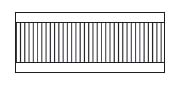
As already alluded to, the fact that sandwich structures are usually co-cured results in facesheet waviness, which may significantly affect the performance of the sandwich and limit the usefulness of the design equations presented so far. One attempt to include the effect of waviness can be found in [9]. A typical cross-section of a [(±45)/(0/90)/(±45)] facesheet on honeycomb core is shown in Figure 10.11 (taken from [9]).
Figure 10.11 Sandwich cross-section showing facesheet and portion of the core (200× magnification from [9])
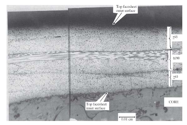
Using Figure 10.11, the waviness of the facesheet at that section cut through the specimen was measured and plotted in Figure 10.12 (taken from [9]). It is evident from Figure 10.12 that the waviness can be significant and its amplitude can approach one-quarter to one-third of the facesheet thickness tf (=0.5717 mm in this case).
Figure 10.12 Waviness of outer surface of facesheet of Figure 10.11 (from [9])
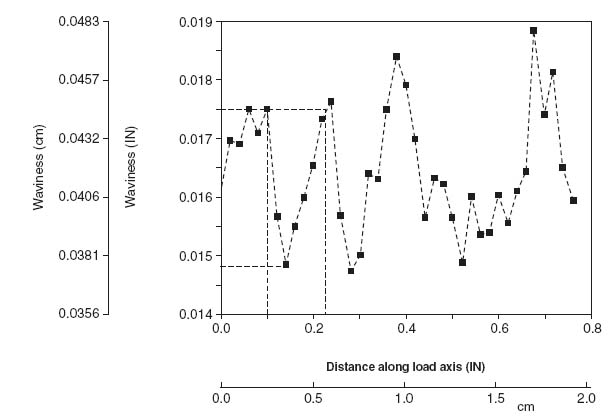
Even though there is an element of randomness in the waviness of Figure 10.12, a main sinusoidal component of a specific amplitude and wavelength can be estimated. Assuming that component is present everywhere in the facesheet, a new model of facesheet deformations under compression accounting for the waviness can be created [9]. This model assumes a sinusoidal shape of the facesheet shown schematically in Figure 10.13. This model permits accounting for the presence of facesheet (light grey colour in Figure 10.13), adhesive (dark grey colour in Figure 10.13), and core and their respective failure modes relatively easily. The model assumes that the waviness shown in Figure 10.13 extends all the way to the edges of the sandwich (perpendicular to the plane of the figure).
Figure 10.13 Sandwich with waviness
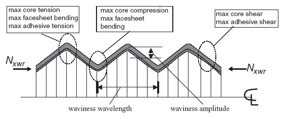
Each of the failure modes shown in Figure 10.13, core tension, core compression, core shear, adhesive tension, adhesive shear and facesheet bending must be checked for, and the most critical will give the failure prediction. This requires accurate knowledge of the corresponding allowables.
A comparison of this model to test results, taken from [9], is shown in Table 10.2. Here, three different facesheet layups and three different cores were used. The predictions range from excellent to barely acceptable (for the last case in Table 10.2). The main reasons for the discrepancies from test results are
Table 10.2 Comparison of wrinkling predictions obtained with a waviness model to test results

Still, using a waviness model is promising and, combined with accurate allowables, can yield very reliable predictions.
To account for the effect of (usually unknown) waviness and other complicating factors, it is customary to knockdown the predictions of Equation (10.20) for symmetric wrinkling by reducing the coefficient in the right-hand side [11]:
Similarly, for antisymmetric wrinkling which, as already mentioned, occurs only in thin cores, Equation (10.22a) is modified as follows [12]:

Equations (10.28) and (10.29) have been shown to be (sometimes very) conservative over a wide variety of facesheet and core materials, including metals.
What has been presented so far is only a small portion of sandwich wrinkling modelling approaches. There are many more models, each with its own range of applicability. A discussion of the accuracy of the various models and their applicability can be found in [13].
10.3.2 Sandwich Wrinkling under Shear
Wrinkling of a sandwich structure can also occur under applied shear load. Since pure shear can be resolved in compression in one direction and tension in the other, the compression portion can cause wrinkling of the sandwich along a line at 45° to the applied shear load (see Figure 10.14). A conservative way to estimate the wrinkling load under shear is to analyse the sandwich as loaded under compression along the 45° line and neglect the tension load. The reason is that in biaxial loading situations with compression and tension, the tension load tends to stabilize the structure and the buckling load is higher than if only compression were applied. This was demonstrated in Figure 6.3 where the buckling load was higher for compression and tension than for biaxial compression.
Figure 10.14 Sandwich under shear with shear load resolved into compression and tension loads
Therefore, conservatively, the equations derived in the previous section for wrinkling under compression can also be used here, provided the relevant quantities Ef, Ec and Gxz are rotated to the direction of applied compression. Of these, the core Young's modulus in the z direction Ec remains unaffected. The facesheet modulus Ef is rotated by 45° by simply rotating the stacking sequence by that angle and calculating the corresponding membrane modulus of the resulting laminate in that direction using Equation (8.6). The core shear modulus G45 also changes if the core is not isotropic in its plane. The corresponding transformation was given by Equation (10.5). So, in the coordinate system ![]() , with compression parallel to the
, with compression parallel to the ![]() axis, the rotated core shear stiffnesses are
axis, the rotated core shear stiffnesses are
(10.5a) 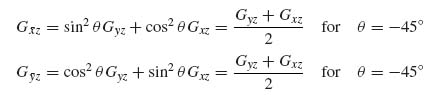
10.3.3 Sandwich Wrinkling under Combined Loads
Wrinkling under combined loads is analysed using interaction curves [7, 14], which are very similar to the interaction curves for buckling of monolithic plates presented in Sections 6.5 and 6.6. A summary of the most common cases is given in Table 10.3. To use Table 10.3 the following ratios are defined:
Table 10.3 Interaction curves for sandwich wrinkling under combined loads
For compression alone,
(10.30) ![]()
where Nxwr is the wrinkling load under compression.
For shear alone,
(10.31) ![]()
where Nxywr is the wrinkling load under shear.
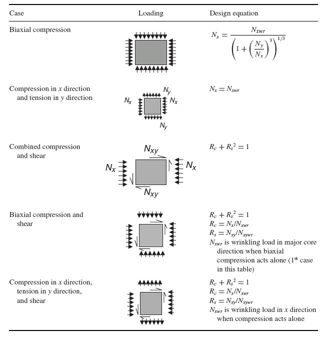
10.4 Sandwich Crimping
This failure mode is shown in Figure 10.15. It occurs when the core shear stiffness is very low and is quite sensitive to the presence of eccentricities (e.g. when the core thickness is not uniform or if there is an abrupt change in the facesheet thickness when many plies are dropped).
Figure 10.15 Sandwich crimping
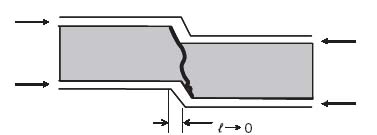
This is a failure mode that is similar to antisymmetric wrinkling with, essentially, zero wavelength (![]() → 0).
→ 0).
10.4.1 Sandwich Crimping under Compression
If the wavelength ![]() of the buckling mode tends to zero, the corresponding buckling load tends to infinity since the buckling load is proportional to 1/
of the buckling mode tends to zero, the corresponding buckling load tends to infinity since the buckling load is proportional to 1/![]() 2. Then, the basic buckling equation for a sandwich under compression, Equation (10.3), can be used:
2. Then, the basic buckling equation for a sandwich under compression, Equation (10.3), can be used:
(10.3) 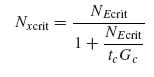
letting NEcrit tend to infinity.
It can be seen that Equation (10.3) is of the form ∞/∞ as NEcrit → ∞, so l'Hopital's rule can be used to determine the limit of Nxcrit. Differentiating numerator and denominator with respect to NEcrit and, subsequently letting NEcrit tend to infinity, the crimping load Nxcrit is shown to be

where Gc is either Gxz or Gyz, whichever is aligned with the direction of the load.
10.4.2 Sandwich Crimping under Shear
A semi-empirical formula is used in this case, which is analogous to Equation (10.32):
(10.33) ![]()
10.5 Sandwich Intracellular Buckling (Dimpling) under Compression
This is a failure mode specific to honeycomb or other open-cell cores. Such representative cores are shown in Figure 10.16. Flex and double-flex core are used in structures with single or compound curvature to allow the sandwich to conform to the curved shape and eliminate anticlastic curvature effects.
Figure 10.16 Cores susceptible to dimpling

When cores as those shown in Figure 10.16 are used, if the cell size is big enough it is possible for the unsupported facesheet between the cell walls to buckle. To analyse this intracellular buckling or dimpling mode requires developing a buckling solution for a composite facesheet with hexagonal or highly irregular (for flex or double-flex cores in Figure 10.16) boundaries. The complexity of such solution is prohibitive. Instead, a one-dimensional column-buckling type solution combining Equations (8.56) and (10.26) with a semi-empirical factor is used:
(10.34a) 
or
(10.34b) 
where s is the core cell size shown in Figure 10.16.
10.6 Attaching Sandwich Structures
As mentioned in Section 10.1, sandwich has superior bending stiffness properties and would be the preferred design configuration had it not been for several failure modes such as wrinkling or crimping that limit its performance. Another problem that limits the usage of sandwich structure is the difficulty of attaching it to adjacent structure with adequate load transfer at the attachment region without undue increase in weight and cost. While it is relatively easy to attach sandwich structure when the applied loads are low, it is quite a challenge to do so for highly loaded structure. Some considerations and options are discussed in the following two sections.
10.6.1 Core Ramp-Down Regions
One of the most common methods of providing adequate means of attachment is through the use of a ramp-down. By eliminating the core at the attachment region one does not have to deal with the fact that core has low compression and shear strengths which would compromise the strength of an attachment. As seen in Figure 10.17, the attachment can be through fasteners or adhesive (or both) connecting monolithic laminates at the edge of the ramp-down region.
Figure 10.17 Attaching sandwich structure through the use of ramp-downs

The monolithic laminate created by eliminating the core (consisting of the two facesheets) may not be sufficient if the loads are high, and local reinforcement may be necessary to transfer bearing and shear loads (Figure 10.18). This creates the additional problem of deciding how and where the extra plies will be dropped off, transitioning to the full depth of the core. Clearly, they cannot all terminate at the edge of the core ramp because the resulting stiffness mismatch would lead to premature failure. In fact, a number of plies must go up the ramp to stiffen it and thus attract some of the load to the upper facesheet in Figure 10.18. This is of particular importance for relatively large values of the ramp angle θ (15° < θ < 40°).
Figure 10.18 Transitioning from monolithic laminate to full-depth core

Consider a situation where some in-plane load, for example shear, is applied at the edge where the monolithic laminate is. The loading is eccentric in that it acts at the neutral axis of the monolithic laminate which is offset from the neutral axis of the full-depth core. This causes a twisting moment. At low loads, the entire shear load stays in the flat facesheet, the bottom facesheet in Figure 10.18. At higher loads, bending of the full-depth core is more pronounced, and a significant fraction of the applied load starts to get transmitted up the ramp into the ramped facesheet (top facesheet in Figure 10.18). This is the reason plies must go up the ramp and into the upper facesheet, to transfer that load without failure. For typical designs of ramped sandwich under shear, 60% of the load stays in the straight (bottom) facesheet and 40% is transmitted up the ramp to the top facesheet.
Since the monolithic region is typically designed for bearing strength (at least when fasteners are used to connect to adjacent structure) and the facesheets away from the ramped regions are designed for buckling and notched strength requirements, the thickness of the monolithic region is, usually, significantly higher than the sum of the thicknesses of the two facesheets. This poses the problem of smoothly transitioning the thicker monolithic laminate to the thinner facesheets. A typical transition with some guidelines is shown in Figure 10.18. Successive plydrops are separated by at least 10 times the thickness of the dropped plies. This is in agreement with the findings of Figure 9.16. At the same time, again consistent with the results of Section 9.2.2, dropping a large number of plies should be avoided because of the high normal and shear stresses created. In addition, dropping many plies at the same location may require machining a step into the core, as shown in Figure 10.18, to accommodate them. Dropping no more than three to four plies at one location usually does not require special provisions such as locally machining the core.
If the thickness difference between the monolithic laminate at the panel edges and the facesheets at the full-thickness portion of the core is large it will be necessary to have a number of plydrop locations transitioning from the edge without core to the full-depth core. It is customary to separate successive plydrops by distances roughly equal to the core thickness, provided other requirements such as the minimum distance between drops = 10× plydrop thickness are not violated. Also, plydrops along the ramp itself are usually avoided.
The discussion so far has been qualitative and draws mostly on previous results from Chapter 9. A detailed analytical approach for evaluating ramp-down regions can be found in [15]. The possibility of facesheet and/or core failures in the ramp region is examined in that reference.
A final word related to the ramp-down angle θ is in order. If the ramp angle is large (Figure 10.19a) the ramp is closer to vertical and it is hard to transfer load to the upper facesheet. Furthermore, the pressure during cure tends to crush the core. For ramp angles between 30° and 45°, curing an extra layer of adhesive prior to curing the facesheets stabilizes the core and eliminates the crushing problem (at the expense of an extra cure cycle for the adhesive layer). On the other hand, large ramp angles take up less space. If the ramp angle is shallow (Figure 10.19b) the ramp is closer to the horizontal, and transferring load to the upper facesheet is easier. However, small ramp angles result in long ramp-down regions which means significant portions of the sandwich panel have core with lower thickness and thus lower bending stiffness. This can cause stability problems. In addition, for small ramp angles, the end of the core, where the monolithic laminate starts, ends up being very thin. This causes handling problems during fabrication and it is hard to keep the core edge from moving and/or getting crushed under pressure during cure.
Figure 10.19 Steep versus shallow ramp-down regions

The optimum ramp angle will depend on which of the factors mentioned above are favoured for a given design and by specific factory practices. Lightly loaded ramps and situations with limited available space tend to favour larger values of θ, while more highly loaded applications will favour lower values of θ which approach a more even distribution of load between the facesheets, provided the local loss of bending stiffness is not prohibitive. For applied bending loads on small panels, where the ramped portions on either side of the panel are a significant fraction of the total panel size, it can be shown that the optimum value of θ is 12–18° (depending on panel size) [15]. This is a result of two opposing tendencies. For large values of θ the core shear and normal stresses are high, and lead to failure. For low values of θ, the core stresses are low, but the deformations are high due to reduced bending stiffness, and they cause failure. The best compromise is reached at intermediate θ values.
10.6.2 Alternatives to Core Ramp-Down
While using a ramp-down has certain advantages, especially for highly loaded situations, it does not come without a price, in particular because of the additional failure modes (core compression or shear) in the ramp-down region that require detailed analysis. Alternatives have been used for a long time and are based on the experience with metal cores [16].
These methods make use of inserts and bushings that span the full depth of the core so there is no need for ramp-down (Figure 10.20). Locally, the core may be densified with higher-density core or other material that has the required compression and shear stiffness to meet the loads exerted by clamp-up of bolts or other localized loads.
Figure 10.20 Attachments of sandwich parts without ramp-downs

In addition to these, bonded configurations making use of special purpose joints such as the ‘pi’ and ‘F’ joints shown in Figure 10.21 can be used. Again, local densification of the core may be necessary. Due to the difficulty in accurately controlling the final thickness of the parts to be connected, and the width of the opening of the ‘pi’ or ‘F’ joint (mainly due to spring-back after cure), paste adhesive is used. Controlling the thickness of the bondline and making sure it is within the required range (too thin leads to early failure, too thick causes eccentricities that lead to high bending-induced loads) is the major challenge for these configurations. In addition, the lack of a reliable nondestructive inspection (NDI) technique, that determines whether the bond has the required strength or not, may either force the designer to use fasteners or to build into the configuration sufficient strength and alternate load paths so that, if a significant portion of the bond is compromised, the remainder can still meet limit load requirements. Despite these issues, bonded joints similar to those in Figure 10.21 have been used successfully in airframe structures (see, e.g. [17, 18]).
Figure 10.21 Alternate means of joining sandwich structures

Finally, for relatively thin cores, transitioning to a thick monolithic laminate that forms an ‘F’ joint is also a possibility and has been used successfully (Figure 10.22).
Figure 10.22 Core transitioning to monolithic laminate without ramp-down (Courtesy of Aurora Flight Sciences)
Exercises
10.1 Prove that for antisymmetric wrinkling to occur, the core thickness must satisfy the following relation:

10.2a Prove that for a simply supported square composite panel for which D11 = D22, the number of half-waves m into which the panel buckles under compression is always 1. What should the condition be between D11 and D22 for the square panel to buckle in two half-waves?
10.2b Assume a layup consisting of n plies of the same material all at the same orientation (not necessarily 0°). Let E be the Young's modulus of a single ply at that orientation, G the corresponding shear modulus, and ν12, ν21 the two Poisson's ratios. Derive analytical expressions for A11, A12, A22, A66, D11, D12, D22, D66 as functions of E, G, ν12, ν21, and the thickness h of the laminates (still having all plies with the same fibre orientation).
10.2c A simply supported square sandwich panel of dimension a and core thickness tc is under a compression load Na (units: force/width). Use the results of Exercises 10.2a and 10.2b to express the buckling load Ncrit as a function of E, G, ν12, ν21, h and tc. Assume now that the material used is plain weave fabric for which Ex = Ey and simplify the expression you derived (ν12, ν21 are replaced by a single Poisson's ratio ν).
10.2d In certain circumstances, optimizing a structure that is likely to fail in more than one failure modes with corresponding loads ‘reasonably’ close to each other is equivalent to making sure that all failure modes occur simultaneously since this guarantees that the structure is not over-designed (and thus heavier than it needs to be) for any of the failure modes. This is not true in general, but it is true in quite a few cases. Assuming that the wrinkling failure and the buckling failure for the simply supported sandwich of Exercise 10.2c above occur at the same time, derive an expression for the facesheet thickness h (independent of tc) and the core thickness tc (which will be a function of h).
10.2e Let a = 381 mm, Na = 175 N/mm. For the facesheet material assume that Ex = Ey = 68.94 GPa, Gxy = 4.826 GPa, νxy = 0.05 and tply = 0.1905 mm. For the core assume Ec = 133.05 MPa (out-of-plane stiffness) and Gxz = 42.05 MPa (shear stiffness in the ribbon direction). If the ribbon direction is aligned with the loading Na and the facesheet consists exclusively of (±45) plies, use the results of Exercise 10.2d to determine the minimum number of plies and minimum facesheet thickness needed. Is this the minimum weight configuration (i.e. is there another pair of values of h, tc that gives lower weight)? For the optimum solution you found are the crimping and intracellular buckling requirements also satisfied? (For the latter assume a core cell size of 6.35 mm.)
10.3a A skin panel has dimensions 1270 × 1016 mm and is loaded in compression (along the long dimension of the panel) with Nx = 121.45 N/mm. A sandwich design is proposed for this application. The skin layup has been fixed to [45/–45/0/core/0/–45/45]. The facesheet material has the following properties:
Two Nomex honeycomb materials are proposed with the properties given below:

Note that in the core material designation, 1/8 and 3/16 denote the cell size (in inches!) and 3.0 the density (in units of lb/ft3). The second material is cheaper than the first and this is the only reason it is considered as a candidate.
Given the ribbon direction call-out shown below, determine the minimum core thickness needed for each type of core material for the sandwich panel not to fail.

10.3b The manufacturing personnel in the factory who will fabricate this panel are very sloppy and careless. The engineer designing the panel is concerned that they will misorient the core in the panel and the ribbon direction will be perpendicular to the load. What is the minimum core thickness needed in this case (which will cover all possible errors in core placement during fabrication)? (Do this problem only for the first of the two core materials).
10.4 (May be done in conjunction with Exercise 8.6 which has the exact same requirements for a stiffener.) Design a sandwich configuration to represent a composite stiffener under compression.
The sandwich design for each stiffener must fit within a 50 × 50 mm rectangle.

The applied load is 35, 000 N (assume it is acting at the centre of gravity of the selected cross-section). The length ![]() of the stiffener is 550 mm.
of the stiffener is 550 mm.
Two composite materials are available and one core material with properties as follows:
| Unidirectional tape graphite/epoxy | Plain weave fabric graphite/epoxy | Nomex core |
| Ex = 131 GPa | 68.9 GPa | |
| Ey = 11.4 GPa | 68.9 GPa | |
| vxy = 0.31 | 0.05 | |
| Gxy = 5.17 GPa | 5.31 GPa | |
| tply = 0.1524 mm | 0.1905 mm | |
| ρ = 1611 kg/m3 | 1611 kg/m3 | 48.2 kg/m3 |
Also assume that the honeycomb core is attached to the facesheet (on either side) with an adhesive layer of density 0.147 kg/m2. (Watch out for the units!) You are allowed to use any of the two graphite/epoxy materials or a combination thereof. Do not worry about any analysis for the adhesive, it is included here only for the weight calculation. Finally, assume a compression strain allowable (accounting for environment, damage and material scatter) of 4500 μs.
Determine the layup and core thickness of the sandwich, observing as many of the design rules as possible. (Note that the core is only allowed to take thickness values that are integral multiples of 3.175 mm; this is to save on machining costs.) Provide a simple sketch of the cross-section that shows the plies, layup, dimensions, etc. Calculate the corresponding weight. If available, compare with the answer from Exercise 8.6.
10.5 (May be done in conjunction with Exercise 7.6.) You are to design a composite panel under compressive load, using sandwich construction. The panel dimensions are 100 × 50 cm and the applied load is 1750 N/mm acting parallel to the 50 cm dimension.

Two composite materials are available and one core material with properties as follows:
| Unidirectional tape graphite/epoxy | Plain weave fabric graphite/epoxy | Nomex core |
| Ex = 131 GPa | 68.9 GPa | |
| Ey = 11.4 GPa | 68.9 GPa | Ec = 133 MPa |
| νxy = 0.31 | 0.05 | |
| Gxy = 5.17 GPa | 5.31 GPa | Gxz = 42.0 MPa |
| tply = 0.1524 mm | 0.1905 mm | Core cell size = 3.2 mm |
| Xt = 2068 MPa | 1378.8 MPa | |
| Xc = 1723 MPa | 1378.8 MPa | |
| Yt = 68.9 MPa | 1378.8 MPa | |
| Yc = 303.3 MPa | 1378.8 MPa | |
| S = 124.1 MPa | 119.0 MPa | |
| ρ = 1611 kg/m3 | 1611 kg/m3 | 48.2 kg/m3 |
Once you determine any strength values needed for any of the layups selected you are to assume the same knockdowns mentioned in Section 5.1.6 for environment, material scatter and damage, that is, any first-ply failure values should be reduced to the design (or allowable) values by multiplying them by 0.8 × 0.65 × 0.8 = 0.416.
Determine the facesheet layup and core thickness for the sandwich panel not to buckle or fail in any other failure mode up to the applied load of 1750 N/mm. Also assume that the honeycomb core is attached to the facesheet (above and below) with an adhesive layer of density 0.147 kg/m2. (Watch out for the units!) For the facesheet, you are allowed to use any of the two graphite/epoxy materials or a combination thereof. Do not worry about any analysis for the adhesive, it is included here only for the weight calculation. The core thickness cannot exceed 5 cm and cannot be any less than 6 mm. Each of the facesheets cannot be thinner than 0.57 mm.
Determine the layup and core thickness of the sandwich, observing as many of the design rules as possible. Provide a simple sketch of the cross-section of the sandwich that shows the plies, layup, dimensions, etc. Calculate the corresponding weight and if available compare with the post-buckled design of Exercise 7.6.
10.6 A sandwich panel is 508 mm long and 203.2 mm wide. The applied loads are Nx = 245.28 N/mm and Nxy = 133.15 N/mm. A fabric material is available with properties:

Also, a core material with properties:

Using only three plies per facesheet and only in the orientations (±45) and/or (0/90) such that each facesheet is symmetric, determine the lightest design. Do not do any crimping or dimpling checks. Also, do not use any knockdowns for material scatter, environments and damage.
10.7 A plain weave fabric composite material is available with the following properties:

Also, a core material is available with the following properties:

Making sure that the facesheet is symmetric and balanced, determine the lowest weight configurations for panels of dimensions a = 1524 mm and b = 1016 mm under shear loads 105, 157.5 and 210 N/mm. The panel is assumed to be simply supported all around.
10.8 If the lowest possible number of plies per facesheet in order to keep moisture out is 3 and the lowest available core thickness is 6.35 mm, determine the lowest weight configuration and the corresponding maximum load under compression given the materials from the previous exercise. The length a and width b are the same as in the previous exercise with a aligned with the x direction. If the applied load (along x) is lower than the maximum value determined here, is sandwich an efficient solution? Note that facesheets do not have to be symmetric in this problem.
References
[1] Carstensen, T., Cournoyer, D., Kunkel, E. and Magee, C., X-cor® Advanced Sandwich Core Material, Proc. 33rd Int. SAMPE Conf., Seattle, WA, November 2001.
[2] Marasco, A.M., Cartié, D.D.R., Partridge, I.K. and Rezai, A., Mechanical Properties Balance in Novel Z-Pinned Sandwich Panels: Out-of-Plane Properties, Composites Part A: Applied Science and Manufacturing, 37, 295–302 (2006).
[3] Plantema, F.J., Sandwich Construction, John Wiley & Sons, New York, 1966.
[4] Timoshenko, S.P. and Gere, J.M., Theory of Elastic Stability, McGraw-Hill, New York, 1961, p. 351.
[5] Whitney, J.M. and Pagano, N.J., Shear Deformation in Heterogeneous Anisotropic Plates, Journal of Applied Mechanics, 37, 1031–1036 (1970).
[6] Hoff, N.J. and Mautner, S.E., The Buckling of Sandwich-Type Panels, Journal of Aeronautical Sciences, 12, 285–297 (1945).
[7] Ley, R.P., Lin, W. and Mbanefo, U., Facesheet Wrinkling in Sandwich Structures, NASA/CR-1999-208994 (1999).
[8] Vadakke, V. and Carlsson, L.A., Experimental Investigation of Compression Failure Mechanisms of Composite Faced Foam Core Sandwich Specimens, Journal of Sandwich Structures and Materials, 6, 327–342 (2004).
[9] Kassapoglou, C., Fantle, S.C. and Chou, J.C., Wrinkling of Composite Sandwich Structures under Compression, Journal of Composites Technology and Research, 17, 308–316 (1995).
[10] Pearce, T.R.A. and Webber, J.P.H., Buckling of Sandwich Panels with Laminated Face Plates, Aeronautical Quarterly, 23, 148–160 (1972).
[11] Bruhn, E.F., Analysis and Design of Flight Vehicle Structures, S.R. Jacobs & Assoc, Indianapolis, IN, 1973, Section C12.10.3.
[12] Sullins, R.T., Smith, G.W. and Spier, D.D, Manual for Structural Stability Analysis of Sandwich Plates and Shells, NASA CR 1457, Section 2, (1969).
[13] Dobyns, A., Correlation of Sandwich Facesheet Wrinkling Test Results with Several Analysis Methods, 51st American Helicopter Society (AHS) Forum, Fort Worth, TX, 1995, pp. 9–11.
[14] Birman, V. and Bert, C.W., Wrinkling of Composite Facing Sandwich Panels under Biaxial Loading, Journal of Sandwich Structures and Materials, 6, 217–237 (2004).
[15] Kassapoglou, C., Stress Determination and Core Failure Analysis in Sandwich Rampdown Structures under Bending Loads, in Fracture of Composites, E. Armanios (ed.), TransTech Publications, Switzerland, 1996, pp. 307–326.
[16] Bruhn, E.F., Analysis and Design of Flight Vehicle Structures, S.R. Jacobs & Assoc., Indianapolis IN, 1973, Section C12.50.
[17] Wong, R., Sandwich Construction in the Starship, Proc. 37th International SAMPE Symposium and Exhibition, Anaheim CA, 9–12 March 1992, pp. 186–197.
[18] Jonas, P., and Aldag, T., Certification of Bonded Composite Structure, SAE Technical Paper Series, Paper 871022, 1987; also presented at SAE General Aviation Aircraft Meeting and Exposition, Wichita, KS, 28–30 April 1987.