
In this chapter, we study the internal structure of the network subsystem provided in FreeBSD. The networking facilities provide a framework within which many network architectures may coexist. A network architecture comprises a set of network-communication protocols, the protocol family; conventions for naming communication endpoints, the address family; and any additional facilities that may fall outside the realm of connection management and data transfer. Networking facilities are accessed through the socket abstraction described in Chapter 11. The network subsystem provides a general-purpose framework within which network services are implemented. These facilities include the following:
• A structured interface to the socket level that allows the development of network-independent application software
• A consistent interface to the hardware devices used to transmit and receive data
• Network-independent support for message routing
• Memory management
We describe the internal structure of the network subsystem in Section 12.1. Then we discuss the interface between the socket layer and the network facilities and examine the interfaces between the layers of software that make up the network subsystem. In Section 12.5, we discuss the routing services used by the network protocols; in Section 12.6, we describe the mechanisms provided to manage buffering and to control congestion. We present the raw-socket interface that provides direct access to lower-level network protocols in Section 12.7. Finally, in Section 12.8, we discuss an assortment of issues and facilities, including out-of-band data, subnetwork addressing, and the address resolution protocol.
After we have discussed the framework in which the network protocols fit, we shall examine the implementations of several existing network protocols in Chapter 13. A detailed description of the internal data structures and functions of the network layers and protocols can be found in Wright & Stevens [1995].
The network subsystem is logically divided into three layers. These three layers manage the following tasks:
- Interprocess data transport
- Internetwork addressing and message routing
- Transmission-media support
The first two layers are made up of modules that implement communication protocols. The software in the third layer generally includes a protocol sublayer, as well as one or more network device drivers.
The topmost layer in the network subsystem is termed the transport layer. The transport layer must provide an addressing structure that permits communication between sockets and any protocol mechanisms necessary for socket semantics, such as reliable data delivery. The second layer, the network layer, is responsible for the delivery of data destined for remote transport or for network-layer protocols. In providing internetwork delivery, the network layer must manage a private routing database or use the systemwide facility for routing messages to their destination host. The bottom layer, the network-interface layer, or link layer, is responsible for transporting messages between hosts connected to a common transmission medium. The network-interface layer is mainly concerned with driving the transmission media involved and doing any necessary link-level protocol encapsulation and decapsulation.
The transport, network, and network-interface layers of the network subsystem correspond to the transport, network, and link layers of the ISO Open Systems Interconnection Reference Model [ISO, 1984], respectively. The internal structure of the networking software is not directly visible to users. Instead, all networking facilities are accessed through the socket layer described in Chapter 11. Each communication protocol that permits access to its facilities exports a set of user request routines to the socket layer. These routines are used by the socket layer in providing access to network services.
The layering described here is a logical layering. The software that implements network services may use more or fewer communication protocols according to the design of the network architecture being supported. For example, raw sockets often use a null implementation at one or more layers. At the opposite extreme, tunneling of one protocol through another uses one network protocol to encapsulate and deliver packets for another protocol and involves multiple instances of some layers.
Early versions of BSD were used as end systems in a network. They were either the source or destination of communication. Although many installations used a workstation as a departmental gateway, dedicated hardware was used to perform the more complex tasks of bridging and routing. At the time of the original design and implementation of the networking subsystem, the possibility of securing data by encrypting packets was still far in the future. Since that initial design, many different uses have been made of the code. Due to the increase in general processor performance, it is now fairly simple to build a bridge or router out of stock parts and the advent of specialized cyptographic coprocessors has made packet encryption practical in a home, cafe, or office environment. These facts conspire to make a discussion of data flow within the network subsystem more complex than it once was.
While the ideas are complex, the code is even more so. Several different implementors have added their particular flavor of change to make their particular application perform in the way they wished, and these changes have led to an overly complex implementation. The basic idea to keep in mind is that there are only four real paths through a network node:
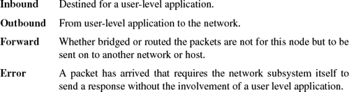
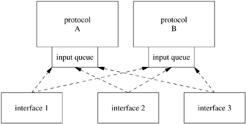
Inbound data received at a network interface flow upward through communication protocols until they are placed in the receive queue of the destination socket. Outbound data flow down to the network subsystem from the socket layer through calls to the transport-layer modules that support the socket abstraction. The downward flow of data typically is started by system calls. Data flowing upward are received asynchronously and are passed from the network-interface layer to the appropriate communication protocol through per-protocol input message queues, as shown in Figure 12.1 (on page 476). The system handles inbound network traffic by splitting the processing of packets between the network driver's upper and lower halves. The lower half of the driver runs in the device's interrupt context and handles the physical interrupts from the device and manages the device's memory. The upper half of the driver runs as an interrupt thread and can either queue packets for the network thread swi_net or process them to completion. FreeBSD 5.2 queues all packets by default. The fine-grained locking of the network code done to support symmetric multiprocessing in FreeBSD has made it possible to preempt interrupt threads that are processing packets without negative side effects, which means that interactive performance does not suffer when a system is under a high network load. A third alternative for packet processing is to have the system poll for packets, and this polling has been added as an experimental feature, but it currently is used only with a few devices and will not be discussed here.
Figure 12.1. Example of upward flow of a data packet in the network subsystem. Key: ETHER—Ethemet header; IP—Internet Protocol header; TCP—Transmission Control Protocol header.
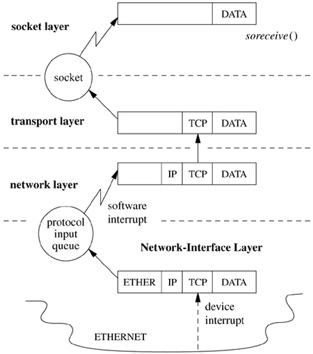
Once the packet has been queued by the device's interrupt thread, the swi_net thread is responsible for handling the packet. This handler is a thread in the kernel whose sole job is to read packets off the queue, and if a message received by a communication protocol is destined for a higher-level protocol, this protocol is invoked directly. If the message is destined for another host (i.e., following the forward path) and the system is configured as a router, the message may be returned to the network-interface layer for retransmission.
A network protocol is defined by a set of conventions, including packet formats, states, and state transitions. A communication-protocol module implements a protocol and is made up of a collection of procedures and private data structures.
Protocol modules are described by a protocol-switch structure that contains the set of externally visible entry points and certain attributes, shown in Figure 12.2. The socket layer interacts with a communication protocol solely through the latter's protocol-switch structure, recording the address of the structure in the socket's so_proto field. This isolation of the socket layer from the networking subsystem is important in ensuring that the socket layer provides users with a consistent interface to all the protocols supported by a system. When a socket is created, the socket layer looks up the domain for the protocol family to find the array of protocol-switch structures for the family (see Section 11.4). A protocol is selected from the array based on the type of socket supported (the pr_type field) and optionally a specific protocol number (the pr_protocol field). The protocol switch has a back pointer to the domain (pr_domain). Within a protocol family, every protocol capable of supporting a socket directly (for example, most transport protocols) must provide a protocol-switch structure describing the protocol. Lower-level protocols such as network-layer protocols may also have protocol-switch entries, although whether they do can depend on conventions within the protocol family.
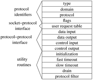
Before a protocol is first used, the protocol's initialization routine is invoked. Thereafter, the protocol will be invoked for timer-based actions every 200 milliseconds if the pr_fasttimo() entry is present, and every 500 milliseconds if the pr_slowtimo() entry point is present. In general, protocols use the slower timer for most timer processing; the major use of the fast timeout is for delayed-acknowledgment processing in reliable transport protocols. The pr_drain() entry is provided so that the system can notify the protocol if the system is low on memory and would like any noncritical data to be discarded. Finally, the pr_pfil() entry gives a hook for packet-filtering calls, which allow a system administrator to drop or modify packets as they are processed by the networking subsystem.
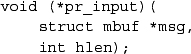
Protocols may pass data between their layers in chains of mbufs (see Section 11.3) using the pr_input() and pr_output() routines. The pr_input() routine passes data up toward the user, whereas the pr_output() routine passes data down toward the network. Similarly, control information passes up and down via the pr_ctlinput() and pr_ctloutput() routines. The table of user request routines, pr_usrreqs(), is the interface between a protocol and the socket level; it is described in detail in Section 12.2.
In general, a protocol is responsible for storage space occupied by any of the arguments passed downward via these procedures and must either pass the space onward or dispose of it. On output, the lowest level reached must free space passed as arguments; on input, the highest level is responsible for freeing space passed up to it. Auxiliary storage needed by protocols is allocated from the mbuf pool. This space is used temporarily to formulate messages or to hold variable-sized socket addresses. (Some protocols also use mbufs for data structures such as state control blocks, although many such uses have been converted to use malloc() directly.) Mbufs allocated by a protocol for private use must be freed by that protocol when they are no longer in use.
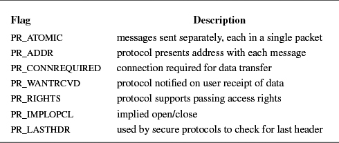
The pr_flags field in a protocol's protocol-switch structure describes the protocol's capabilities and certain aspects of its operation that are pertinent to the operation of the socket level; the flags are listed in Table 12.1. Protocols that are connection based specify the PR_CONNREQUIRED flag, so that socket routines will never attempt to send data before a connection has been established. If the PR_WANTRCVD flag is set, the socket routines will notify the protocol when the user has removed data from a socket's receive queue. This notification allows a protocol to implement acknowledgment on user receipt and also to update flow-control information based on the amount of space available in the receive queue. The PR_ADDR field indicates that any data placed in a socket's receive queue by the protocol will be preceded by the address of the sender. The PR_ATOMIC flag specifies that each user request to send data must be done in a single protocol send request; it is the protocol's responsibility to maintain record boundaries on data to be sent. This flag also implies that messages must be received and delivered to processes atomically. The PR_RIGHTS flag indicates that the protocol supports the transfer of access rights; this flag is currently used by only those protocols in the local communication domain. Connection-oriented protocols that allow the user to set up, send data, and tear down a connection all in a single sendto call have the PR_IMPLOPCL flag set. The PR_LASTIIDR flag is used by secure protocols, such as IPSec, where several headers must be processed to get at the actual data.
Each network interface configured in a system defines a link-layer path through which messages can be sent and received. A link-layer path is a path that allows a message to be sent via a single transmission to its destination, without network-level forwarding. Normally, a hardware device is associated with this interface, although there is no requirement that one be (e.g., all systems have a software loopback interface). In addition to manipulating the hardware device, a network-interface module is responsible for encapsulation and decapsulation of any link-layer protocol header required to deliver a message to its destination. For common interface types, the link-layer protocol is implemented in a separate sublayer that is shared by various hardware drivers. The selection of the interface to use in sending a packet is a routing decision carried out at the network-protocol layer. An interface may have addresses in one or more address families. Each address is set at boot time using an ioctl system call on a socket in the appropriate domain; this operation is implemented by the protocol family after the network interface verifies the operation with an ioctl entry point provided by the network interface. The network-interface abstraction provides protocols with a consistent interface to all hardware devices that may be present on a machine.
An interface and its addresses are defined by the structures shown in Figure 12.3 (on page 480). As interfaces are found at startup time, the ifnet structures are initialized and are placed on a linked list. The network-interface module generally maintains the ifnet interface data structure as part of a larger structure that also contains information used in driving the underlying hardware device. Similarly, the ifaddr interface address structure is often part of a larger structure containing additional protocol information about the interface or its address. Because network socket addresses are variable in size, each protocol is responsible for allocating the space referenced by the address, mask, and broadcast or destination address pointers in the ifaddr structure.
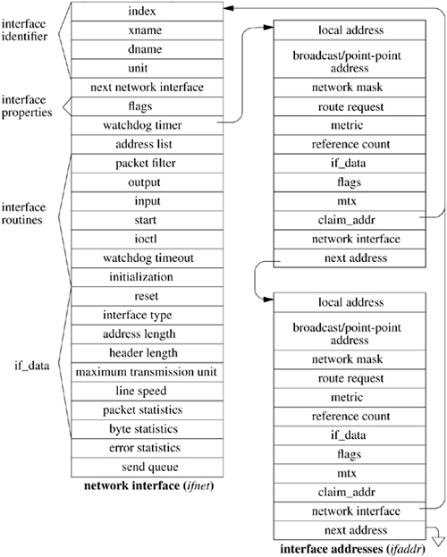
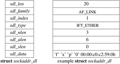
Each network interface is identified in two ways: a character string identifying the driver plus a unit number for the driver (e.g. fxp0) and a binary systemwide index number. The index is used as a shorthand identifier—for example, when a route that refers to the interface is established. As each interface is found during system startup, the system creates an array of pointers to the ifnet structures for the interfaces. It can thus locate an interface quickly given an index number, whereas the lookup using a string name is less efficient. Some operations, such as interface address assignment, name the interface with a string for the user's convenience because performance is not critical. Other operations, such as route establishment, pass a newer style of identifier that can use either a string or an index. The new identifier uses a sockaddr structure in a new address family, AF_LINK, indicating a link-layer address. The family-specific version of the structure is a sockaddr_dl structure, shown in Figure 12.4, which may contain up to three identifiers. It includes an interface name as a string plus a length, with a length of zero denoting the absence of a name. It also includes an interface index as an integer, with a value of zero indicating that the index is not set. Finally, it may include a binary link-level address, such as an Ethernet address, and the length of the address. An address of this form is created for each network interface as the interface is configured by the system and is returned in the list of local addresses for the system along with network protocol addresses (see later in this subsection). Figure 12.4 shows a structure describing an Ethernet interface that is the first interface on the system; the structure contains the interface name, the index, and the link-layer (Ethernet) address.
Figure 12.4. Link-layer address structure. The box on the left names the elements of the sockaddr_dl structure. The box on the right shows sample values for these elements for an Ethernet interface. The sdl_data array may contain a name (if sdl_nlen is nonzero, a link-layer address (if sdl_alen is nonzero), and an address selector (if sdl_slen is nonzero). For an Ethernet, sdl_data contains a three-character name followed by a unit number, fxpO, followed by a 6-byte Ethernet address.
The interface data structure includes an if_data structure, which contains the externally visible description of the interface. It includes the link-layer type of the interface, the maximum network-protocol packet size that is supported, and the sizes of the link-layer header and address. It also contains numerous statistics, such as packets and bytes sent and received, input and output errors, and other data required by network-management protocols.
The state of an interface and certain externally visible characteristics are stored in the if_flags field described in Table 12.2 (on page 482). The first set of flags characterizes an interface. If an interface is connected to a network that supports transmission of broadcast messages, the IFF_BROADCAST flag will be set, and the interface's address list will contain a broadcast address to be used in sending and receiving such messages. If an interface is associated with a point-to-point hardware link (e.g., a leased line circuit), the IFF_POINTOPOINT flag will be set, and the interface's address list will contain the address of the host on the other side of the connection. (Note that the broadcast and point-to-point attributes are mutually exclusive.) These addresses and the local address of an interface are used by network-layer protocols in filtering incoming packets. The IFF_MULTICAST flag is set by interfaces that support multicast packets in addition to IFF_BROADCAST. Multicast packets are sent to one of several group addresses and are intended for all members of the group.
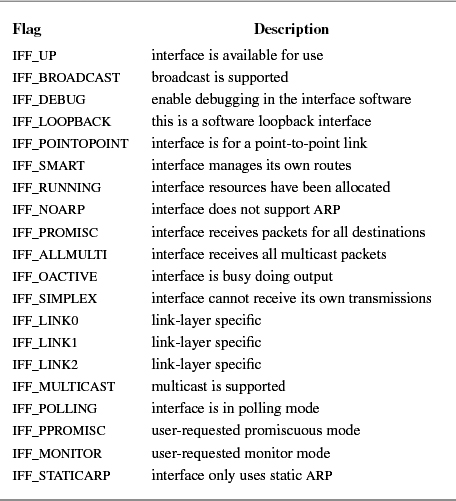
Additional interface flags describe the operational state of an interface. An interface sets the IFF_RUNNING flag after it has allocated system resources and has posted an initial read on the device that it manages. This state bit avoids multiple allocation requests when an interface's address is changed. The IFF_UP flag is set when the interface is configured and is ready to transmit messages. The IFF_OACTIVE flag is used to coordinate between the if_output and if_start routines, described later in this subsection; it is set when no additional output may be attempted. The IFF_PROMISC flag is set by network-monitoring programs to enable promiscuous reception: when they wish to receive packets for all destinations rather than for just the local system. Packets addressed to other systems are passed to the monitoring packet filter but are not delivered to network protocols. The IFF_ALLMULTI flag is similar, but it applies to only multicast packets and is used by multicast forwarding agents. The IFF_SIMPLEX flag is set by Ethernet drivers whose hardware cannot receive packets that they send. Here, the output function simulates reception of broadcast and (depending on the protocol) multicast packets that have been sent. Finally, the IFF_DEBUG flag can be set to enable any optional driver-level diagnostic tests or messages. Three flags are defined for use by individual link-layer drivers (IFF_LINKO, IFF_LINK1, and IFF_LINK2). They can be used to select link-layer options, such as Ethernet medium type.
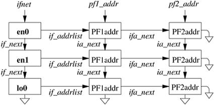
Interface addresses and flags are set with ioctl requests. The requests specific to a network interface pass the name of the interface as a string in the input data structure, with the string containing the name for the interface type plus the unit number. Either the SIOCSIFADDR request or the SIOCAIFADDR request is used initially to define each interface's addresses. The former sets a single address for the protocol on this interface. The latter adds an address, with an associated address mask and broadcast address. It allows an interface to support multiple addresses for the same protocol. In either case, the protocol allocates an ifaddr structure and sufficient space for the addresses and any private data and links the structure onto the list of addresses for the network interface. In addition, most protocols keep a list of the addresses for the protocol. The result appears somewhat like a two-dimensional linked list, as shown in Figure 12.5. An address can be deleted with the SIOCDIFADDR request.
Figure 12.5. Network-interface and protocol data structures. The linked list of ifnet structures appears on the left side of the figure. The ifaddr structures storing the addresses for each interface are on a linked list headed in the ifnet structure and shown as a horizontal list. The ifaddr structures for most protocols are linked together as well, shown in the vertical lists headed by pf1_addr and pf2_addr.
The SIOCSIFFLAGS request can be used to change an interface's state and to do site-specific configuration. The destination address of a point-to-point link is set with the SIOCSIFDSTADDR request. Corresponding operations exist to read each value. Protocol families also can support operations to set and read the broadcast address. Finally, the SIOCGIFCONF request can be used to retrieve a list of interface names and protocol addresses for all interfaces and protocols configured in a running system. Similar information is returned by a newer mechanism based on the sysctl system call with a request in the routing protocol family (see Sections 12.5 and 14.6). These requests permit developers to construct network processes, such as a routing daemon, without detailed knowledge of the system's internal data structures.
Each interface has a queue of packets to be transmitted and routines used for initialization and output. The if_output() routine accepts a packet for transmission and normally handles link-layer encapsulation and queueing that are independent of the specific hardware driver in use. If the IFF_OACTIVE flag is not set, the output routine may then invoke the driver's if_start() function to begin transmission. The start function then sets the IFF_OACTIVE flag if it is unable to accept additional packets for transmission; the flag will be cleared when transmission completes. The if_done() entry point is provided as a callback function for use when the output queue is emptied. This facility is not yet used, but it is intended to support striping of data for a single logical interface across multiple physical interfaces.
An interface may also specify a watchdog timer routine and a timer value that (if it is nonzero) the system will decrement once per second, invoking the timer routine when the value expires. The timeout mechanism is typically used by interfaces to implement watchdog schemes for unreliable hardware and to collect statistics that reside on the hardware device.
The interface from the socket routines to the communication protocols is through the user request table pr_usrreqs() and the pr_ctloutput() routine, which are defined in the protocol-switch table for each protocol. When the socket layer requires services of a supporting protocol, it makes a call to one of the functions in Table 12.3. The control-output routine implements the getsockopt and setsockopt system calls; the user-request routines are used for all other operations. Calls to pr_ctloutput() specify SOPT_GET to get the current value of an option, or SOPT_SET to set the value of an option.
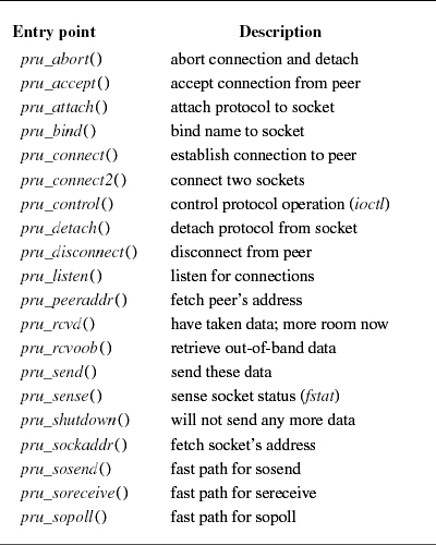
Calls to the user-request routines have a routine-specific signature, but the first argument is always a pointer to a socket structure, which specifies the socket for which the operation is intended. An mbuf data chain is supplied for output operations and for certain other operations where a result is to be returned. A pointer to a sockaddr structure is supplied for address-oriented requests, such as pru_bind(), pru_connect(), and pru_send() (when an address is specified—e.g., the sendto call). Where it is used, the control parameter is a pointer to an optional mbuf chain containing protocol-specific control information passed via the sendmsg call. Each protocol is responsible for disposal of the data mbuf chains on output operations. A nonzero return value from a user-request routine indicates an error number that should be passed to higher-level software. A description of each of the possible requests follows:
• pru_attach(): attach protocol to socket. When a protocol is first bound to a socket (with the socket system call), the protocol module's pru_attach() routine is called. It is the responsibility of the protocol module to allocate any resources necessary. The attach routine will always precede any of the other operations and will occur only once per socket.
• pru_detach(): detach protocol from socket. This operation is the inverse of the attach routine and is used at the time that a socket is deleted. The protocol module may deallocate any resources that it allocated for the socket in a previous pru_attach() call.
• pru_bind(): bind address to socket. When a socket is initially created, it has no address bound to it. This routine binds an address to an existing socket. The protocol module must verify that the requested address is valid and is available for use.
• pru_listen(): listen for incoming connections. The listen request routine indicates that the user wishes to listen for incoming connection requests on the associated socket. The protocol module should make any state changes needed to meet this request (if possible). A call to the listen routine always precedes any request to accept a connection.
• pru_connect(): connect socket to peer. The connect request routine indicates that the user wants to establish an association. The addr parameter describes the peer to which a connection is desired. The effect of a connect request may vary depending on the protocol. Stream protocols use this request to initiate establishment of a network connection. Datagram protocols simply record the peer's address in a private data structure, where they use it as the destination address of all outgoing packets and as a source filter for incoming packets. There are no restrictions on how many times a connect routine may be used after an attach, although most stream protocols allow only one connect call.
• pru_accept(): accept pending connection. Following a successful listen request and the arrival of one or more connections, this routine is called to indicate that the user is about to accept a socket from the queue of sockets ready to be returned. The socket supplied as a parameter is the socket that is being accepted; the protocol module is expected to fill in the supplied buffer with the address of the peer connected to the socket.
• pru_disconnect(): disconnect connected socket. This routine eliminates an association created with the connect routine. It is used with datagram sockets before a new association is created; it is used with stream protocols only when the socket is closed.
• pru_shutdown(): shut down socket data transmission. This call indicates that no more data will be sent. The protocol may, at its discretion, deallocate any data structures related to the shutdown or the protocol may leave all of that work for its pru_detach() routine. The module may also notify a connected peer of the shutdown at this time.
• pru_rcvd(): data were received by user. This routine is called only if the protocol entry in the protocol-switch table includes the PR_WANTRCVD flag. When the socket layer removes data from the receive queue and passes them to the user, this routine will be called in the protocol module. This routine may be used by the protocol to trigger acknowledgments, refresh windowing information, initiate data transfer, and so on. This routine is also called when an application attempts to receive data on a socket that is in the confirming state, indicating that the protocol must accept the connection request before data can be received (see Section 11.5).
• pru_send(): send user data. Each user request to send data is translated into one or more calls to the protocol module's pru_send() routine. A protocol may indicate that a single user send request must be translated into a single call to the pru_send() routine by specifying the PR_ATOMIC flag in its protocol description. The data to be sent are presented to the protocol as a chain of mbufs, and an optional address is supplied in the addr parameter. The protocol is responsible for preserving the data in the socket's send queue if it is not able to send them immediately or if it may need them at some later time (e.g., for retransmission). The protocol must eventually pass the data to a lower level or free the mbufs.
• pru_abort(): abnormally terminate service. This routine effects an abnormal termination of service. The protocol should delete any existing associations.
• pru_control(): do control operation. The control request routine is called when a user does an ioctl system call on a socket and the ioctl is not intercepted by the socket routines. This routine allows protocol-specific operations to be provided outside the scope of the common socket interface. The cmd parameter contains the actual ioctl request code. The data parameter contains any data relevant to the command being issued and the ifp parameter contains a pointer to a network-interface structure if the ioctl operation pertains to a particular network interface.
• pru_sense(): sense socket status. The sense request routine is called when the user makes an fstat system call on a socket; it requests the status of the associated socket. This call returns a standard stat structure that typically contains only the optimal transfer size for the connection (based on buffer size, windowing information, and maximum packet size).
• pru_rcvoob(): receive out-of-band data. This routine requests that any out-of-band data now available are to be returned. An mbuf is passed to the protocol module, and the protocol should either place data in the mbuf or attach new mbufs to the one supplied if there is insufficient space in the single mbuf. An error may be returned if out-of-band data are not (yet) available or have already been consumed. The flags parameter contains any options, such as MSG_PEEK, that should be observed while this request is carried out.
• pru_sockaddr(): retrieve local socket address. This routine returns the local address of the socket if one has been bound to the socket. The address is returned in the nam parameter, which is a pointer to a sockaddr structure.
• pru_peeraddr(): retrieve peer socket address. This routine returns the address of the peer to which the socket is connected. The socket must be in a connected state for this request to succeed. The address is returned in the nam parameter, which is a pointer to a sockaddr structure.
• pru_connect2(): connect two sockets without binding addresses. In this routine, the protocol module is supplied two sockets and is asked to establish a connection between the two without binding any addresses, if possible. The system uses this call in implementing the socketpair system call.
• pru_fasttimo(): service fast timeout. This routine is called when the fast timeout expires (200ms). The fast-timeout routine cannot be called from the socket layer.
• pru_slowtimo(): service slow timeout. This routine is called when the slow timeout has expired (500ms). This slow-timeout routine cannot be called from the socket layer.
A call to the control-output routine is of the form
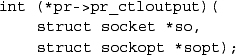
where so is the socket to be modified and sopt is a socket option structure.
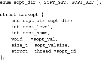
The direction is either SOPT_SET to set an option or SOPT_GET to retrieve it. The sopt_level member indicates the layer of software that should interpret the option request. A sopt_level of SOL_SOCKET is specified to control an option at the socket layer. When the option is to be processed by a protocol module below the socket layer, level is set to the appropriate protocol number (the same number used in the socket system call). Each level has its own set of option names; this name is interpreted only by the targeted layer of software. The rest of the structure contains a pointer to the value being passed into or out of the module, the size of the pointed-to data, and a pointer to a thread structure. If the operation takes place wholly inside the kernel, then the pointer to the thread structure is null.
In supporting the getsockopt and setsockopt system calls, the socket layer always invokes the control-output routine of the protocol attached to the socket. To access lower-level protocols, each control-output routine must pass control-output requests that are not for itself downward to the next protocol in the protocol hierarchy. Chapter 13 describes some of the options provided by the protocols in the Internet communication domain.
The interface between protocol modules uses the pr_usrreqs() routines as well as the pr_ctloutput() routine. The pr_usrreqs() and pr_ctloutput() routines are used by the socket layer to communicate with protocols.
Although imposing a standard calling convention for all of a protocol's entry points might theoretically permit an arbitrary interconnection of protocol modules, it would be difficult in practice. Crossing of a protocol-family boundary—for example, between IPv4 and IPX—would require a network address to be converted from the format of the caller's domain to the format of the receiver's domain. Consequently, connection of protocols in different communication domains is not generally supported, and calling conventions for the routines listed in the preceding paragraph are typically standardized on a per-domain basis. (However, the system does support encapsulation of packets from one protocol into packets of a protocol in another family to tunnel one protocol through another.)
In this section, we briefly examine the general framework and calling conventions of protocols. In Chapter 13, we examine specific protocols to see how they fit into this framework.
Each protocol has a different calling convention for its output routine. This lack of standardization is one of the things that prevents protocol modules from being freely interchanged with each other in arbitrary stacks, such as is done in the STREAMS system [Ritchie, 1984]. Thus far this kind of standardization has not been considered necessary because each protocol stack tends to stand on its own without ever borrowing from others. An arbitrary stacking of protocol modules would also complicate the interpretation of network addresses in each module, since each would have to check to make sure that the address made some sense to them in their domain.
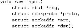
The simplest example of a protocol output routine often uses a calling convention designed to send a single message on a connection; for example,
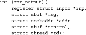
would send a message contained in msg on a socket described by protocol control block inp. Special address and control information are passed in addr and control, respectively.
Upper-level protocol input routines are usually called by the network software-interrupt task once the network-level protocol has located the protocol identifier. They have stricter conventions than do output routines because they are called via the protocol switch. Depending on the protocol family, they may receive a pointer to a control block identifying the connection, or they may have to locate the control block from information in the received packet. A typical calling convention is
In this example, the incoming packet is passed to a transport protocol in an mbuf msg with the network protocol header still in place for the transport protocol to use, as well as the length of the header, hlen, so that the header can be removed. The protocol does the endpoint-level demultiplexing based on information in the network and transport headers.
This routine passes control information (i.e., information that might be passed to the user but does not consist of data) upward from one protocol module to another. The common calling convention for this routine is
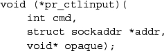
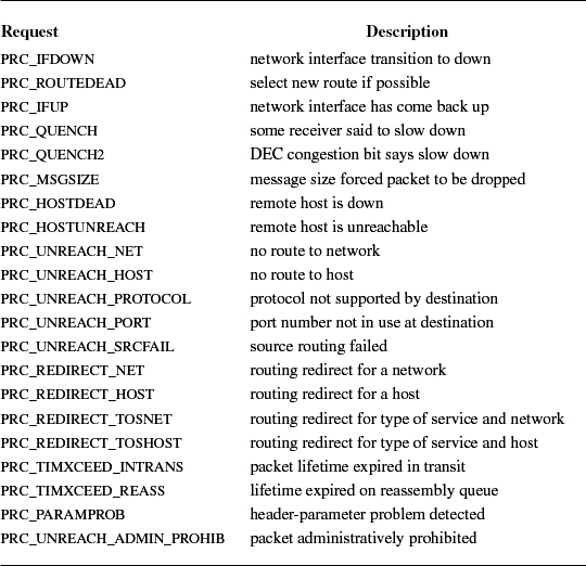
The cmd parameter is one of the values shown in Table 12.4. The addr parameter is the remote address to which the condition applies. Many of the requests have been derived from the Internet Control Message Protocol (ICMP) [Postel, 1981] and from error messages defined in the 1822 host (Internet Message Processor) convention [BBN, 1978]. Some protocols may pass additional parameters internally, such as local addresses or more specific information.
The lowest layer in the set of protocols that constitutes a protocol family must interact with one or more network interfaces to transmit and receive packets. It is assumed that any routing decisions have been made before a packet is sent to a network interface; a routing decision is necessary to locate any interface at all. Although there are four paths through any network stack, there are only two cases with which we should be concerned in the interaction between protocols and network interfaces: transmission of a packet and receipt of a packet. We shall consider each separately.
If a protocol has chosen an interface identified by ifp, a pointer to a network interface structure, the protocol transmits a fully formatted network-level packet with the following call:
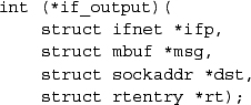
The output routine for the network interface transmits the packet msg to the protocol address specified in dst or returns an error number. In reality, transmission may not be immediate or successful; typically, the output routine validates the destination address, queues the packet on its send queue, and primes an interrupt-driven routine to transmit the packet if the interface is not busy. For unreliable media, such as Ethernet, successful transmission simply means that the packet has been placed on the cable without a collision. In contrast, a reliable, point-to-point network such as X.25, can guarantee proper delivery of a packet or give an error indication for each packet that was not successfully transmitted. The model employed in the networking system attaches no promise of delivery to the packets presented to a network interface and thus corresponds most closely to the Ethernet. Errors returned by the output routine are only those that can be detected immediately and are normally trivial in nature (network down, no buffer space, address format not handled, etc.). If errors are detected after the call has returned, the protocol is not notified.
When messages are transmitted in a broadcast network such as Ethernet, each network interface must formulate a link-layer address for each outgoing packet. The interface layer must understand each protocol address format that it supports to formulate corresponding link-layer addresses. The network layer for each protocol family selects a destination address for each message and then uses that address to select the appropriate network interface to use. This destination address is passed to the interface's output routine as a sockaddr structure. Presuming that the address format is supported by the interface, the interface must map the destination protocol address into an address for the link-layer protocol associated with the transmission medium that the interface supports. This mapping may be a simple algorithm, it may require a table lookup, or it may require more involved techniques, such as use of the address resolution protocol described in Section 12.8.
Network interfaces receive packets and dispatch packets to the appropriate network-layer protocol according to information encoded in the link-layer protocol header. Each protocol family must have one or more protocols that constitute the network layer described in Section 12.1. In this system, each network-layer protocol has an input-packet queue assigned to it. Incoming packets received by a network interface are queued in a protocol's input packet queue, and the network thread handles network-layer processing; see Figure 12.6. Similar queues are used to store packets awaiting transmission by network device drivers.
Several macros are available for manipulating packet queues:
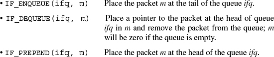
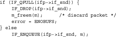
Packet queues have a maximum length associated with them as a simple form of congestion control. The macro IF_QFULL() can be used to determine whether a queue is full; if it is, another macro, IF_DROP(), can then be used to record the event in statistics kept for the queue. Each queue is protected by a mutex so that threads on different processors cannot accidentally interfere with each other's transmissions. Any macro that manipulates the queue first locks the mutex, then makes its change, and finally releases the mutex.
As an example, the following code fragment could be used in a network interface's output routine:
On receiving a packet, a network interface decodes the packet type, strips the link-layer protocol header, records the identity of the receiving interface, and then dispatches the packet to the appropriate link-layer module. Above the link layer each protocol has an input handler routine and input queue, which are registered with the network thread via the netisr_register() routine.
For example, an Ethernet device driver queues its packets in the Ethernet link layer by calling ether_demux(), which then calls netisr_dispatch() to enqueue packets for a particular protocol. netisr_dispatch() is a generic routine that hands packets to protocols. It in turn uses a generic routine if_handoff() to actually enqueue the packet with the following code:
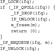
Once the packet is placed in the queue, the schednetisr() macro schedules the network thread so that it will carry on the processing of the packet.
Entries on a protocol's input queue are mbuf chains with a valid packet header containing the packet's length and a pointer to the network interface on which the packet was received. The pointer to the interface has many potential uses, such as deciding when to generate routing redirect messages. The protocol's input routine does not dequeue the packet but is handed an mbuf pointing to the packet by the network thread. It is the network thread that dequeues packets and then calls the protocol's input routine.
While an entry is being dequeued from an input queue, the network thread blocks all other packets from entering the protocol by locking the network thread mutex. The lock is held to ensure that pointers in the queue data structure are not altered. Once a message is dequeued, it is processed; if there is information in the packet for a higher-level protocol, the message is passed upward.
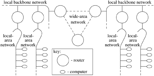
The networking system was designed for a heterogenous network environment, in which a collection of local-area networks are connected at one or more points through routers, as shown in the example in Figure 12.7. Routers are nodes with multiple network interfaces, one on each local-area or long-haul network. In such an environment, issues related to packet routing are important. Certain of these issues, such as congestion control, are handled simplistically in FreeBSD (see Section 12.6). For others, the network system provides simple mechanisms on which more involved policies can be implemented. These mechanisms ensure that, as these problems become better understood, their solutions can be incorporated into the system. Note that at the time of the original design of this part of the system, a network node that forwarded network-level packets was generally known as a gateway. The current term is router. We use both terms interchangeably, in part because the system data structures continue to use the name gateway.
This section describes the facilities provided for packet routing. The routing facilities were designed for use by singly connected and multiply connected hosts, as well as for routers. There are several components involved in routing, illustrated in Figure 12.8. The design of the routing system places some components within the kernel and others at user level. Routing is actually an overbroad term. In a complex, modern network there are two major components to a routing system. The gathering and maintenance of route information (i.e., which interfaces are up, what the costs are in terms of using particular links, etc.) as well as the implementation of routing policies (which interfaces can be used to forward traffic in an administrative sense) are handled at user level by routing daemons. The actual forwarding of packets, which is the selection of the interface on which a packet will be sent, is handled by the kernel.
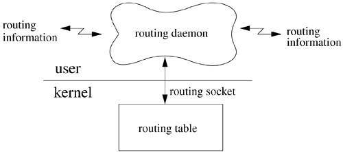
The forwarding mechanism is a simple lookup that provides a first-hop route (a specific network interface and immediate destination) for each outbound packet. The current design places enough information in the kernel for packets to be sent on their way without external help; all other components are outside the kernel. User-level routing daemons communicate with the kernel via a routing socket to manipulate the kernel forwarding table and to listen for internal changes such as interfaces being brought up or down. Each of these components is described in this section.
The kernel routing mechanism implements a routing table for looking up first-hop routes (or next hop, when forwarding packets). It includes two distinct portions: a data structure describing each specific route (a routing entry) and a lookup algorithm to find the correct route for each possible destination. This subsection describes the entries in the routing table, and the next subsection explains the lookup algorithm. A destination is described by a sockaddr structure with an address family, a length, and a value. Routes are classified in the following ways: as either host or network routes and as either direct or indirect. The host-network distinction determines whether the route applies to a specific host or to a group of hosts with a portion of their addresses in common—usually a prefix of the address. For host routes, the destination address of a route must exactly match the desired destination; the address family, length, and bit pattern of the destination must match those in the route. For network routes, the destination address in the route is paired with a mask. The route matches any address that contains the same bits as the destination in the positions indicated by bits set in the mask. A host route is a special case of a network route, in which all the mask bits are set, and thus no bits are ignored in the comparison. Another special case is a wildcard route—a network route with an empty mask. Such a route matches every destination and serves as a default route for destinations not otherwise known. This fallback network route is usually pointed to a router that can then make more informed routing decisions.
The other major distinction between types of routes is either direct or indirect. A direct route is one that leads directly to the destination: The first hop of the path is the entire path, and the destination is on a network shared with the source. Most routes are indirect: The route specifies a router on a local network that is the first-hop destination for the packet. Much of the literature (especially for Internet protocols) refers to a local-remote decision, where an implementation checks first whether a destination is local to an attached network or is remote. In the first case, a packet is sent locally (via the link layer) to the destination; in the latter case, it is sent to a router that can forward it to the destination. In the FreeBSD implementation, the local-remote decision is made as part of the routing lookup. If the best route is direct, then the destination is local. Otherwise, the route is indirect, the destination is remote, and the route entry specifies the router for the destination. In either case, the route specifies only the first-hop gateway—a link-level interface to be used in sending packets—and the destination for the packets in this hop if different from the final destination. This information allows a packet to be sent via a local interface to a destination directly reachable via that interface—either the final destination or a router on the path to the destination. This distinction is needed when the link-layer encapsulation is done. If a packet is destined for a peer that is not directly connected to the source, the packet header will contain the address of the eventual destination, whereas the link-layer protocol header will address the intervening router.
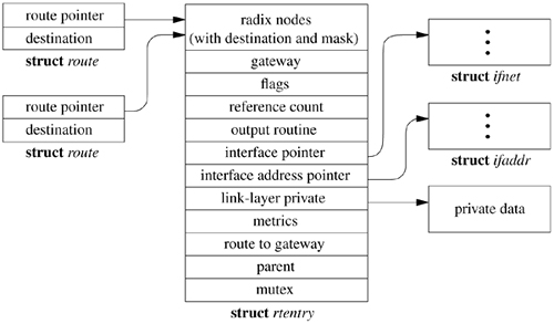
The network system maintains a set of routing tables that is used by protocols in selecting a network interface to use in delivering a packet to its destination. These tables are composed of entries of the form shown in Table 12.5.
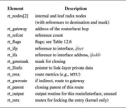
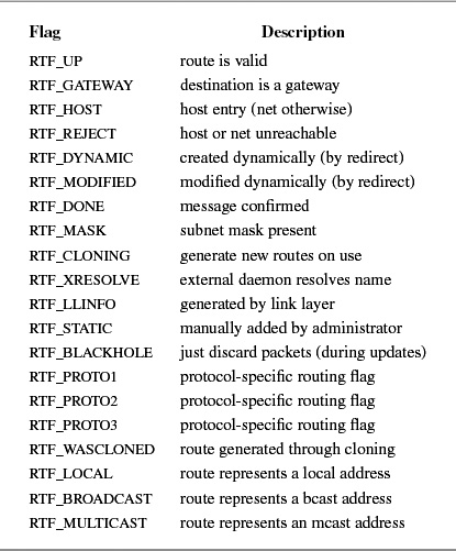
Routing entries are stored in an rtentry structure, which contains a reference to the destination address and mask (unless the route is to a host, in which case the mask is implicit). The destination address, the address mask, and the gateway address are variable in size and thus are placed in separately allocated memory. Routing entries also contain a reference to a network interface, a set of flags that characterize the route, and optionally a gateway address. The flags indicate a route's type (host or network, direct or indirect) and the other attributes shown in Table 12.6 (on page 498). The route entry also contains a field for use by the link-layer driver, a set of metrics, and a mutex for locking the entry. The RTF_HOST flag in a routing-table entry indicates that the route applies to a single host, using an implicit mask containing all the bits of the address. The RTF_GATEWAY flag in a routing-table entry indicates that the route is to a router and that the link-layer header should be filled in from the rt_gateway field, instead of from the final destination address. The route entry contains a field that can be used by the link layer to cache a reference to the direct route for the router. The RTF_UP flag is set when a route is installed. When a route is removed, the RTF_UP flag is cleared, but the route entry is not freed until all users of the route have noticed the failure and have released their references. The route entry contains a reference count because it is allocated dynamically and cannot be freed until all references have been released. The RTF_CLONING flag indicates that a route is a generic route that must be cloned and made more specific before use. This flag is usually used for link-layer routes that apply to a directly attached network, and the cloned routes are generally host routes for hosts on that network that contain some link-level information about that host. When a route is cloned, an external agent may be invoked to complete the link-layer information needed for a destination. Other flags (RTF_REJECT and RTF_BLACKHOLE) mark the destination of the route as being unreachable, causing either an error or a silent failure when an attempt is made to send to the destination. Reject routes are useful when a router receives packets for a cluster of addresses from the outside but may not have routes for all hosts or networks in the cluster at all times. It is undesirable for packets with unreachable destinations to be sent outside the cluster via a default route because the default router would send back such packets for delivery within the cluster. Black-hole routes are used during routing transients when a new route may become available shortly.
Many connection-oriented protocols wish to retain information about the characteristics of a particular network path. Some of this information can be estimated dynamically for each connection, such as the round-trip time or path MTU. It is useful to cache such information so that the estimation does not need to begin anew for each connection [Mogul & Deering, 1990]. The routing entry contains a set of route metrics stored in a rt_metrics_lite structure that may be set externally or may be determined dynamically by the protocols. These metrics include the maximum packet size for the path, called the maximum transmission unit (MTU); the lifetime for the route; and the number of packets that have been sent using this route. In versions of FreeBSD prior to 5.2 path MTU discovery was implemented using a much larger structure, called rt_metrics. Most of the fields contained in the rt_metrics structure were related only to TCP, and so they were moved from the routing entry structure into the TCP code.
When a route is added or created by cloning, and when a route is deleted, the link layer is called via the ifa_rtrequest entry point stored in the ifaddr structure for this interface address. The link layer can allocate private storage associated with the route entry. This feature is used with direct routes to networks that are marked as cloning routes; the link layer can use this mechanism to manage link-layer address-translation information for each host. The address translation can be arranged within the system—it can be handled outside the kernel when the RTF_XRESOLVE flag is set.
Given a set of routing entries describing various destinations, from specific hosts to a wildcard route, a routing lookup algorithm is required. The lookup algorithm in FreeBSD uses a modification of the radix search trie [Sedgewick, 1990]. (The initial design was to use a PATRICIA search, also described in Sedgewick [1990], which differs only in the details of storage management.) The radix search algorithm provides a way to find a bit string, such as a network address, in a set of known strings. Although the modified search was implemented for routing lookups, the radix code is implemented in a more general way so that it can be used for other purposes. For example, the filesystem code uses a radix tree to manage information about clients to which filesystems can be exported. Each kernel route entry begins with the data structures for the radix tree, including an internal radix node and a leaf node that refers to the destination address and mask.
The radix search algorithm uses a binary tree of nodes beginning with a root node for each address family. Figure 12.9 (on page 500) shows an example radix tree. A search begins at the root node and descends through some number of internal nodes until a leaf node is found. Each internal node requires a test of a specific bit in the string, and the search descends in one of two directions depending on the value of that bit. The internal nodes contain an index of the bit to be tested, as well as a precomputed byte index and mask for use in the test. A leaf node is marked with a bit index of -1, which terminates the search. For example, a search for the address 127.0.0.1 (the loopback address) with the tree in Figure 12.9 would start at the head and would branch left when testing bit 0, right at the node for bit 1, and right on testing bit 31. This search leads to the leaf node containing a host route specific to that host; such a route does not contain a mask but uses an implicit mask with all bits set.
Figure 12.9. Example radix tree. This simplified example of a radix tree contains routes for the IPv4 protocol family, which uses 32-bit addresses. The circles represent internal nodes, beginning with the head of the tree at the top. The bit position to be tested is shown within the circle. Leaf nodes are shown as rectangles containing a key (a destination address, listed as four decimal bytes separated by dots) and the corresponding mask (in hexadecimal). Some interior nodes are associated with masks found lower in the tree, as indicated by dashed arrows.
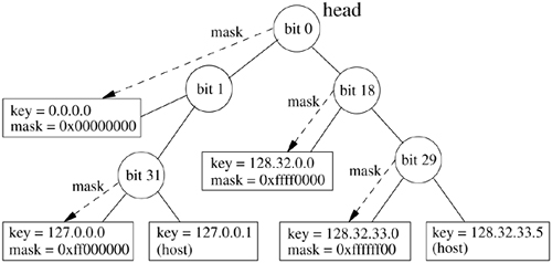
This lookup technique tests the minimum number of bits required to distinguish among a set of bit strings. Once a leaf node is found, either it specifies the specific bit string in question or that bit string is not present in the tree. This algorithm allows a minimal number of bits to be tested in a string to lookup an unknown, such as a host route; however, it does not provide for partial matching as required by a routing lookup for a network route. Thus, the routing lookup uses a modified radix search, in which each network route includes a mask, and nodes are inserted into the tree such that longer masks are found earlier in the search [Sklower, 1991]. Interior nodes for subtrees with a common prefix are marked with a mask for that prefix. (Masks generally select a prefix from an address, although the mask does not need to specify a contiguous portion of the address.) As the routing lookup proceeds, the internal nodes that are passed are associated with masks that increase in specificity. If the route that is found at the leaf after the lookup is a network route, the destination is masked before comparison with the key, thus matching any destination on that network. If the leaf node does not match the destination, one of the interior nodes visited during the route lookup should refer to the best match. After a lookup does not find a match at the leaf node, the lookup procedure iterates backward through the tree, using a parent pointer in each node. At each interior node that contains a mask, a search is made for the part of the destination under that mask from that point. For example, a search for the address 128.32.33.7 in the tree in Figure 12.9 would test bits 0, 18, and 29 before arriving at the host route on the right (128.32.33.5). Because this address is not a match, the search moves up one level, where a mask is found. The mask is a 24-bit prefix, and it is associated with the route to 128.32.33.0, which is the best match. If the mask was not a prefix (in the code, a route with a mask specifying a prefix is called a normal route), a search would have been required for the value 128.32.33.7 starting from this point.
The first match found is the best match for the destination; that is, it has the longest mask for any matching route. Matches are thus found by a combination of a radix search, testing 1 bit per node on the way down the tree, plus a full comparison under a mask at the leaf node. If the leaf node (either host or network) does not match, the search backtracks up the tree, checking each parent with a mask until a match is found. This algorithm avoids a complete comparison at each step when searching down the tree, which would eliminate the efficiency of the radix search algorithm. It is optimized for matches to routes with longer masks and performs least efficiently when the best match is the default route (the route with the shortest mask).
Another complication of using a radix search is that a radix tree does not allow duplicated keys. There are two possible reasons for a key to be duplicated in the tree: Either multiple routes exist to the same destination or the same key is present with different masks. The latter case is not a complete duplicate, but the two routes would occupy the same location in the tree. The routing code does not support completely duplicate routes, but it supports multiple routes that differ in only the mask. When the addition of a route causes a key to be duplicated, the affected routes are chained together from a single leaf node. The routes are chained in order of mask significance, most specific mask first. If the masks are contiguous, longer masks are considered to be more specific (with a host route considered to have the longest possible mask). If a routing lookup visits a node with a duplicated key when doing a masked comparison (either at the leaf node or while moving back up the tree), the comparison is repeated for each duplicate node on the chain, with the first successful comparison producing the best match.
As we noted, FreeBSD does not support multiple routes to the same destination (identical key and mask). The main reason to support multiple paths would be to allow the load to be split among the paths but interleaving of traffic across the available paths would often be suboptimal. A better design would be to add a pointer to an output function in each route. Most routes would copy the output pointer for the interface used by the route. Routes for which multiple paths were available would be represented by a virtual route containing references to the individual routes, which would not be placed in the radix tree. The virtual route would interpose an intermediate output function that would distribute packets to the output functions for the individual routes. This scheme would allow good packet interleaving even when a path was used by a single connection. Although the output routine field has been added to the rtentry structure, it is not in use in the code as of FreeBSD 5.2.
A routing redirect is a control request from a protocol to the routing system to modify an existing routing-table entry or to create a new routing-table entry. Protocols usually generate such requests in response to redirect messages that they receive from routers. Routers generate redirect messages when they recognize that a better route exists for a packet that they have been asked to forward. For example, if two hosts, A and B, are on the same network, and host A sends a packet to host B via a router C, then C will send a redirect message to A indicating that A should send packets to B directly.
On hosts where exhaustive routing information is too expensive to maintain (e.g., SOHO routers, DSL modems, PDAs and other embedded systems), the combination of wildcard routing entries and redirect messages can be used to provide a simple routing-management scheme without the use of a higher-level policy process. Current connections can be rerouted after notification of the protocols by the protocols' pr_ctlinput() entries. Statistics are kept by the routing-table routines on the use of routing-redirect messages and on the latter's effect on the routing tables. A redirect causes the gateway for a route to be changed if the redirect applies to all destinations to which the route applies; otherwise, a new host route is cloned from the appropriate network route. Cloned host routes can easily pollute the routing table because an automated method for removing stale host routes created by redirects does not exist in the system. A user-level routing daemon will normally clean up stale host routes, but most hosts do not run routing daemons.
A protocol accesses the routing tables through three routines: one to allocate a route, one to free a route, and one to process a routing-redirect control message. The routine rtalloc() allocates a route; it is called with a pointer to a route structure, which contains the desired destination, as shown in Figure 12.10, and a pointer that will be set to reference the routing entry that is the best match for the destination. The destination is recorded so that subsequent output operations can check whether the new destination is the same as the previous one, allowing the same route to be used. The route returned is assumed to be held by the caller until released with a call to the RTFREE macro. All accesses to the routing table must be properly locked in FreeBSD and the RTFREE macro handles the locking as well as decrementing the route's reference count, freeing the route entry when the reference count reaches zero. TCP uses a host cache to hold onto routes for the duration of the connection's lifetime. Connectionless protocols, such as UDP, allocate and free routes whenever the routes' destination address changes. The rtalloc() routine simply checks whether the route already contains a reference to a valid route. If no route is referenced or the route is no longer valid, rtalloc() calls the rtalloc1 () routine to lookup a routing entry for the destination, passing a flag indicating whether the route will be used or is simply being checked. If packets will be sent, the route is created by cloning if necessary.
The rtredirect() routine is called to process a redirect control message. It is called with a destination address and mask, the new gateway to that destination, and the source of the redirect. Redirects are accepted from only the current router for the destination. If a nonwildcard route exists to the destination, the gateway entry in the route is modified to point at the new gateway supplied. Otherwise, a new host route is cloned from an existing network route in the routing table. Routes to interfaces and routes to gateways that are not directly accessible from the host are ignored.
The kernel routing facilities deliberately refrain from making policy decisions. Instead, routing policies are determined by user processes, which then add, delete, or change entries in the kernel routing tables. The decision to place policy decisions in a user process implies that routing-table updates may lag a bit behind the identification of new routes or the failure of existing routes. This period of instability is normally short if the routing process is implemented properly. Internet-specific advisory information, such as ICMP error messages, may also be read from raw sockets (described in Section 12.7).
Several routing-policy processes have been implemented. The system standard routing daemon, routed, uses the Routing Information Protocol (RIP) [Hedrick, 1988]. Many sites that require the use of other routing protocols or more configuration options than are provided by routed use either a commercial package or the open source Quagga Routing Suite [Ishiguro, 2003].
User-level processes that implement routing policy and protocols require an interface to the kernel routing table so that they can add, delete, and change kernel routes.
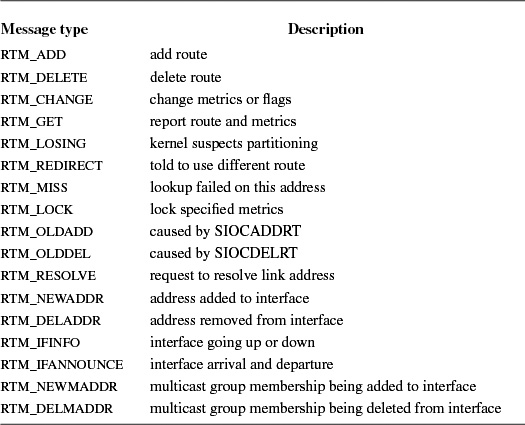
The interface to the kernel routing layer in FreeBSD uses a socket to communicate with the kernel routing layer. A privileged process creates a raw socket in the routing protocol family, AF_ROUTE, and then passes messages to and from the kernel routing layer. This socket operates like a normal datagram socket, including queueing of messages received at the socket, except that communication takes place between a user process and the kernel. Messages include a header with a message type identifying the action, as listed in Table 12.7. Messages to the kernel are requests to add, modify, or delete a route, or are requests for information about the route to a specific destination. The kernel sends a message in reply with the original request, an indication that the message is a reply, and an error number in case of failure. Because routing sockets are raw sockets, each open routing socket receives a copy of the reply and must filter for the messages it wants. The message header includes a process ID and a sequence number so that each process can determine whether this message is a reply to its own request and can match replies with requests. The kernel also sends messages as indications of asynchronous events, such as redirects and changes in local interface state. These messages allow a daemon to monitor changes in the routing table made by other processes, events detected by the kernel, and changes to the local interface addresses and state. The routing socket is also used to deliver requests for external resolution of a link-layer route when the RTF_XRESOLVE flag is set on a route entry.
Requests to add or change a route include all the information needed for the route. The header has a field for the route flags listed in Table 12.6, and contains a rt_metrics structure of metrics that may be set or locked. The only metric that may be set is the MTU. All other metrics are ignored but were kept for backward compatibility with software that used the routing socket interface prior to FreeBSD 5.2. The header also carries a bit vector that describes the set of addresses carried in the message; the addresses follow the header as an array of variable-sized sockaddr structures. A destination address is required, as is a mask for network routes. A gateway address is generally required as well. The system normally determines the interface to be used by the route from the gateway address, using the interface shared with that gateway. By convention, direct routes contain the local address of the interface to be used. In some cases, the gateway address is not sufficient to determine the interface, and an interface address can be passed as well, generally using a sockaddr_dl structure containing the interface name or index (see Section 12.1).
A major factor affecting the performance of a protocol is the buffering policy. Lack of a proper buffering policy can force packets to be dropped, cause false windowing information to be emitted by protocols, fragment memory, and degrade the overall host performance. Because of these problems, most systems allocate a fixed pool of memory to the networking system and impose a policy optimized for normal network operation.
The FreeBSD networking system is not dramatically different in this respect. At boot time, a fixed amount of memory is allocated by the networking system for mbufs and mbuf clusters. At later times, more system memory may be requested for mbuf clusters as the need arises, up to a preconfigured limit; at no time, however, is this memory ever returned to the system. It would be possible to reclaim memory from network buffers but in the environments where the system has been used, storage for network packets has not been an issue, and thus storage reclamation has been left unimplemented.
When a socket is created, the protocol reserves some amount of buffer space for send and receive queues. These amounts define the high watermarks used by the socket routines in deciding when to block and unblock a process. The reservation of space does not currently result in any action by the memory-management routines.
Protocols that provide connection-level flow control base their decisions on the amount of space in the associated socket queues. That is, windows sent to peers are calculated based on the amount of free space in the socket's receive queue, whereas utilization of the send window received from a peer is dependent on the high watermark of the send queue.
Incoming packets from the network are always received unless memory allocation fails. However, each network-layer protocol input queue has an upper bound on the queue's length, and any packets exceeding that bound are discarded. It is possible for a host to be overwhelmed by excessive network traffic (e.g., if the host is acting as a router that connects a high-bandwidth network to a low-bandwidth network). As a defense mechanism, the queue limits can be adjusted to throttle network-traffic load on the system. Discarding packets is not always a satisfactory solution to this problem (simply dropping packets is likely to increase the load on a network); the queue lengths were incorporated mainly as a safeguard mechanism. On the other hand, limiting output queue lengths can be valuable on hosts that route traffic from a high-bandwidth network to a low-bandwidth network. The queue limit should be sufficiently high that transient overload can be handled by buffering, but allowing the queue to be too large causes network delays to increase to unacceptable levels.
A raw socket allows privileged users direct access to a protocol other than those normally used for transport of user data—for example, network-level protocols. Raw sockets are intended for knowledgeable processes that wish to take advantage of some protocol feature not directly accessible through the normal interface or for the development of protocols built atop existing protocols. For example, the ping program is implemented using a raw ICMP socket (see Section 13.8). The raw IP socket interface attempts to provide an identical interface to the one a protocol would have if it were resident in the kernel.
The raw socket support is built around a generic raw socket interface, possibly augmented by protocol-specific processing routines. This section describes only the core of the raw socket interface; details specific to particular protocols are not discussed. Some protocol families (including IPv4) use private versions of the routines and data structures described here.
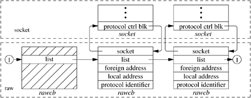
Every raw socket has a protocol control block of the form shown in Figure 12.11. Raw control blocks are kept on a singly linked list for performing lookups during packet dispatch. Associations may be recorded in fields referenced by the control block and may be used by the output routine in preparing packets for transmission. The rcb_proto field contains the protocol family and protocol number with which the raw socket is associated. The protocol, family, and addresses are used to filter packets on input, as described in the next subsection.
A raw socket is datagram oriented: Each send or receive on the socket requires a destination address. Destination addresses may be supplied by the user or referenced via pointers to sockaddr structures in the control block and automatically installed in the outgoing packet by the output routine. If routing is necessary, it must be performed by an underlying protocol.
Input packets are assigned to raw sockets based on a simple pattern-matching scheme. Each protocol (and potentially some network interfaces) gives unassigned packets to the raw input routine with the call
Input packets are placed into the input queues of all raw sockets that match the header according to the following rules:
- The protocol family of the socket and header agree.
- If the protocol number in the socket is nonzero, then it agrees with that found in the packet header.
- If a local address is defined for the socket, the address format of the socket's local address is the same as the packet's destination address, and the two addresses agree exactly.
- Rule 3 is applied to the socket's foreign address and the packet's source address.
A basic assumption in the pattern-matching scheme is that addresses present in the control block and packet header (as constructed by the network interface and any raw input-protocol module) are in a canonical form that can be compared on a bit-for-bit basis. If multiple sockets match the incoming packet, the packet is copied as needed.
In this section, we discuss several aspects of the network subsystem that are not easy to categorize.
The ability to process out-of-band data is a facility specific to the stream-socket and sequenced-packet-socket abstractions. Little agreement appears to exist on what out-of-band data's semantics should be. TCP defines a notion called urgent data, in which in-line data are marked for urgent delivery. The protocol provides a mark on the data stream delimiting urgent data from subsequent normal data. The ISO/OSI protocols [Burruss, 1980] and numerous other protocols provide a fully independent logical transmission channel along which out-of-band data are sent. In addition, the number of data that can be sent in an out-of-band message varies from protocol to protocol, from 1 bit to 512 bytes or more.
A stream socket's notion of out-of-band data has been defined as the lowest reasonable common denominator. Out-of-band data are expected to be transmitted out of the normal sequencing and flow-control constraints of the data stream. A minimum of 1 byte of out-of-band data and one outstanding out-of-band message is expected to be provided by protocols supporting out-of-band messages. It is a protocol's prerogative to support larger-sized messages or more than one outstanding out-of-band message at a time.
Out-of-band data may be maintained by the protocol, stored separately from the socket's receive queue. They may also be prepended to the normal receive queue marked as out-of-band data. A socket-level option, SO_OOBINLINE, is provided to force all out-of-band data to be placed in the normal receive queue when urgent data are received. This option is provided because the 4.2BSD TCP implementation removed 1 byte of data from the data stream at the urgent mark for separate presentation. However, this removal caused problems when additional urgent data were sent before the first such byte was received by the application.
Placement of out-of-band data in the normal data stream can permit a protocol to hold several out-of-band messages simultaneously. This mechanism can avoid the loss of out-of-band messages caused by a process that responds slowly.
The address resolution protocol (ARP) is a link-level protocol that provides a dynamic address-translation mechanism for networks that support broadcast or multicast communication [Plummer, 1982]. ARP maps 32-bit IPv4 addresses to 48-bit Ethernet addresses. Although ARP is not specific either to IPv4 protocol addresses or to Ethernet, the FreeBSD network subsystem supports only that combination, although it makes provision for additional combinations to be added. ARP is incorporated into the network-interface layer, although it logically sits between the network and network-interface layers.
The general idea of ARP is simple. A set of translations from network addresses to link-layer addresses is maintained. When an address-translation request is made to the ARP service by a network interface and the requested address is not in ARP's set of known translations, an ARP message is created that specifies the requested network address and an unknown link-layer address. This message is then broadcast by the interface with the expectation that a host attached to the network will know the translation—usually because the host is the intended target of the original message. If a response is received in a timely fashion, the ARP service uses the response to update its translation tables and to resolve the pending request, and the requesting network interface is then called to transmit the original message.
In practice, the simplicity of this algorithm is complicated by the necessity to avoid stale translation data, to minimize broadcasts when a target host is down, and to deal with failed translation requests. In addition, it is necessary to deal with packets for which transmission is attempted before the translation is completed. The ARP translation tables are implemented as a part of the routing table. The route to a local Ethernet is set up as a cloning route so that individual host routes will be created for each local host when referenced. When the route is cloned, the link layer creates an empty ARP entry associated with the route. The network output routine normally requires a routing lookup or a cached route, and it now passes a reference to the route to the interface output function.
A request is made to resolve an IPv4 address to an Ethernet address for an outgoing message by the call
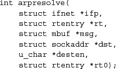
ARP first checks its tables to see whether the destination address is a broadcast or multicast address, in which cases the Ethernet address can be calculated directly. Otherwise, it checks whether the route entry that was passed already contains a complete translation that has not timed out. If so, the gateway value in the route entry is a link-layer address for the destination, and its value is returned in desten for use as the destination address of the outgoing packet. If the link-layer address is not known or has timed out, ARP must queue the outgoing message for future transmission, and must broadcast a message requesting the Internet address translation. The time is recorded in the ARP entry when a request is broadcast, and no further broadcasts are made within the same second if additional transmissions are attempted. If another translation request is made before a reply is received, the queued message is discarded and only the newer one is saved. After some number of broadcasts without a reply (normally 5, in no less than 5 seconds), the route is changed to a reject route with an expiration time after 20 seconds, causing host-down errors to be returned in response to attempts to reach the host within that time.
At a later time—preferably before the timer has expired on the queued message—ARP will receive a response to its translation request. The received message is processed by the ether_demux.() routine, as invoked from the network thread. Because the packet has a packet type of ARP, it is enqueued for the arpintr() routine, analogous to other network-level protocol input routines. The ARP packet is processed to locate the translation entry in the routing table. If the message completes a pending translation, the entry is updated and the original message is passed back to the network interface for transmission. This time, the resultant call to arpresolve() will succeed without delay.
ARP input handling must cope with requests for the host's own address, as well as responses to translation requests that the host generated. The input module also watches for responses from other hosts that advertise a translation for its own IPv4 address. This monitoring is done to ensure that no two hosts on the same network believe that they have the same address (although this error may be detected, ARP's only recourse is to log a diagnostic message).
ARP normally times out completed translation entries in its cache after 20 minutes and incomplete translation entries after about 5 seconds. Entries may be marked permanent, however, in which case they are never removed. Entries may also be marked published, allowing one host to act as a surrogate for other hosts that do not support ARP or to act as a proxy for a host that is not on the Ethernet but is reached via a router.
12.1 Name two key data structures used in the networking subsystem that are important in ensuring that the socket-layer software is kept independent of the networking implementation.
12.2 What work is done by the lower half of a network device driver? What work is done by the upper half of a network device driver?
12.3 Which routines in the protocol switch are called by the socket layer? Explain why each of these routines is called.
12.4 Assume that a reliably-delivered-message socket (SOCK_RDM) is a connectionless socket that guarantees reliable delivery of data and that preserves message boundaries. Which flags would a protocol that supported this type of socket have set in the pr_flags field of its protocol-switch entry?
12.5 Give an example of a network interface that is useful without an underlying hardware device.
12.6 Give two reasons why the addresses of a network interface are not in the network-interface data structure.
12.7 Why is the name or address of a socket kept at the network layer rather than at the socket layer?
12.8 Why does FreeBSD not attempt to enforce a rigid protocol-protocol interface structure?
12.9 Describe two tasks performed by a network-interface output routine.
12.10 Why is the identity of the network interface on which each message is received passed upward with the message?
12.11 Which routing policies are implemented in the kernel?
12.12 Describe three types of routes that can be found in the routing table that differ by the type of destination to which they apply.
12.13 What routing facility is designed mainly to support workstations?
12.14 What is a routing redirect? For what is it used?
12.15 Why do the output-packet queues for each network interface have limits on the number of packets that may be queued?
12.16 What does the SO_OOBINLINE socket option do? Why does it exist?
*12.17 Explain why it is impossible to use the raw socket interface to support parallel protocol implementations—some in the kernel and some in user mode. What modifications to the system would be necessary to support this facility?
*12.18 Previous versions of the system used a hashed routing lookup for a destination as a host or as a network. Name two ways in which the radix search algorithm in FreeBSD is more capable.
References
BBN, 1978. BBN,
"Specification for the Interconnection of Host and IMP," Technical Report 1822, Bolt, Beranek, and Newman, Cambridge, MA, May 1978.
Burruss, 1980.
J. Burruss, "Features of the Transport and Session Protocols," Report No. ICST/HLNP-80-1, National Bureau of Standards, Washington, DC, March 1980.
Hedrick, 1988.
C. Hedrick, "Routing Information Protocol," RFC 1058, available from http://www.faqs.org/rfcs/rfcl058.html, June 1988.
Ishiguro, 2003.
K. Ishiguro, Quagga, available from www.quagga.net, August 2003.
ISO, 1984.
, "Open Systems Interconnection: Basic Reference Model," ISO 7498, International Organization for Standardization, available from the American National Standards Institute, 1430 Broadway, New York, NY 10018, 1984.
Mogul & Deering, 1990.
J. Mogul & S. Deering, "Path MTU Discovery," RFC 1191, available from http://www.faqs.org/rfcs/rfcll91.html, November 1990.
Plummer, 1982.
D. Plummer, "An Ethernet Address Resolution Protocol," RFC 826, available from http://www.faqs.org/rfcs/rfc826.html, November 1982.
Postel, 1981.
J. Postel, "Internet Control Message Protocol," RFC 792, available from http://www.faqs.org/rfcs/rfc792.html, September 1981.
Ritchie, 1984.
D. Ritchie, "A Stream Input-Output System," AT&T Bell Laboratories Technical Journal, , no. 8-2, pp. 1897-1910, October 1984.