
Chapter 12 presented the network-communications architecture of FreeBSD. In this chapter, we examine the network protocols implemented within this framework. The FreeBSD system supports several major communication domains including IPv4, IPv6, Xerox Network Systems (NS), ISO/OSI, and the local domain (formerly known as the UNIX domain). The local domain does not include network protocols because it operates entirely within a single system. The IPv4 protocol suite was the first set of protocols implemented within the network architecture of 4.2BSD. Following the release of 4.2BSD, several proprietary protocol families were implemented by vendors within the network architecture. However, it was not until the addition of the Xerox NS protocols in 4.3BSD that the system's ability to support multiple network-protocol families was visibly demonstrated. Although some parts of the protocol interface were previously unused and thus unimplemented, the changes required to add a second network-protocol family did not substantially modify the network architecture. The implementation of the ISO/OSI networking protocols, as well as other changing requirements, led to a further refinement of the network architecture in 4.4BSD. Two new protocols that were added to the system, IPv6 and IPSec, required several changes because of its need to coexist simultaneously with IPv4. Those changes, as well as IPv6 and IPSec, are presented at the end of this chapter.
In this chapter, we concentrate on the organization and implementation of the IPv4 protocols. This protocol implementation is the standard on which the current Internet is built because it was publicly available when many vendors were looking for tuned and reliable communication protocols. Throughout this chapter we use Internet and IPv4 interchangeably. Specific mention will be made when talking about the new IPv6 protocols, which are meant to eventually supplant IPv4. After describing the overall architecture of the IPv4 protocols, we shall examine their operation according to the structure defined in Chapter 12. We shall also describe the significant algorithms used by the protocols within IPv4. We then shall discuss changes that the developers made in the system motivated by aspects of the IPv6 protocols and their implementation.
IPv4 was developed under the sponsorship of DARPA, for use on the ARPANET [DARPA, 1983; McQuillan & Walden, 1977]. The protocols are commonly known as TCP/IP, although TCP and IP are only two of the many protocols in the family. These protocols do not assume a reliable subnetwork that ensures delivery of data. Instead, IPv4 was devised for a model in which hosts were connected to networks with varying characteristics and the networks were interconnected by routers. The Internet protocols were designed for packet-switching networks using datagrams sent over links such as Ethernet that provide no indication of delivery.
This model leads to the use of at least two protocol layers. One layer operates end to end between two hosts involved in a conversation. It is based on a lower-level protocol that operates on a hop-by-hop basis, forwarding each message through intermediate routers to the destination host. In general, there exists at least one protocol layer above the other two: It is the application layer. The three layers correspond roughly to levels 3 (network), 4 (transport), and 7 (application) in the ISO Open Systems Interconnection reference model [ISO, 1984].
The protocols that support this model have the layering illustrated in Figure 13.1. The Internet Protocol (IP) is the lowest-level protocol in the Model; this level corresponds to the ISO network layer. IP operates hop-by-hop as a datagram is sent from the originating host to the destination via any intermediate routers. It provides the network-level services of host addressing, routing, and, if necessary, packet fragmentation and reassembly if intervening networks cannot send an entire packet in one piece. All the other protocols use the services of IP. The Transmission Control Protocol (TCP) and User Datagram Protocol (UDP) are transport-level protocols that provide additional facilities to applications that use IP. Each protocol adds a port identifier to IP's host address so that local and remote sockets can be identified. TCP provides connection-oriented, reliable, unduplicated, and flow-controlled transmission of data; it supports the stream socket type in the Internet domain. UDP provides a data checksum for checking integrity in addition to a port identifier, but otherwise adds little to the services provided by IP. UDP is the protocol used by datagram sockets in the Internet domain. The Internet Control Message Protocol (ICMP) is used for error reporting and for other, simple network-management tasks; it is logically a part of IP but, like the transport protocols, is layered above IP. It is usually not accessed by users. Raw access to the IP and ICMP protocols is possible through raw sockets (see Section 12.7 for information on this facility).
Figure 13.1. IPv4 protocol layering. Key: TCP—Transmission Control Protocol; UDP—User Datagram Protocol; IP—Internet Protocol; ICMP—Internet Control Message Protocol.

The Internet protocols were designed to support heterogeneous host systems and architectures that use a wide variety of internal data representations. Even the basic unit of data, the byte, was not the same on all host systems; one common type of host supported variable-sized bytes. The network protocols, however, require a standard representation. This representation is expressed using the octet—an 8-bit byte. We shall use this term as it is used in the protocol specifications to describe network data, although we continue to use the term byte to refer to data or storage within the system. All fields in the Internet protocols that are larger than an octet are expressed in network byte order, with the most significant octet first. The FreeBSD network implementation uses a set of routines or macros to convert 16-bit and 32-bit integer fields between host and network byte order on hosts (such as PC systems) that have a different native ordering.
An IPv4 address is a 32-bit number that identifies the network on which a host resides as well as uniquely identifying a network interface on that host. It follows that a host with network interfaces attached to multiple networks has multiple addresses. Network addresses are assigned in blocks by Regional Internet Registries (RIRs) to Internet Service Providers (ISPs), which then dole out addresses to companies or individual users. If address assignment were not done in this centralized way, conflicting addresses could arise in the network, and it would be impossible to route packets correctly.
Historically IPv4 addresses were rigidly divided into three classes (A, B, and C) to address the needs of large, medium, and small networks [Postel, 1981a]. Three classes proved to be too restrictive and also too wasteful of address space. The current IPv4 addressing scheme is called Classless Inter-Domain Routing (CIDR) [Fuller et al., 1993]. In the CIDR scheme each organization is given a contiguous group of addresses described by a single value and a netmask. For example, an ISP might have a group of addresses defined by an 18-bit netmask. This means that the network is defined by the first 18 bits, and the remaining 14 bits can potentially be used to identify hosts in the network. In practice, the number of hosts is less because the ISP will further break up this space into smaller networks, which will reduce the number of bits that can effectively be used. It is because of this scheme that routing entries store arbitrary netmasks with routes.
Each Internet address assigned to a network interface is maintained in an in_ifaddr structure that contains a protocol-independent interface-address structure and additional information for use in the Internet domain (see Figure 13.2). When an interface's network mask is specified, it is recorded in the ia_subnetmask field of the address structure. The network mask, ia_netmask, is still calculated based on the type of the network number (class A, B, or C) when the interface's address is assigned, but this is no longer used to determine whether a destination is on or off the local subnet. The system interprets local Internet addresses using ia_subnetmask value. An address is considered to be local to the subnet if the field under the subnetwork mask matches the subnetwork field of an interface address.

On networks capable of supporting broadcast datagrams, 4.2BSD used the address with a host part of zero for broadcasts. After 4.2BSD was released, the Internet broadcast address was defined as the address with a host part of all is [Mogul, 1984]. This change and the introduction of subnets both complicated the recognition of broadcast addresses. Hosts may use a host part of 0s or 1s to signify broadcast, and some may understand the presence of subnets, whereas others may not. For these reasons, 4.3BSD and later BSD systems set the broadcast address for each interface to be the host value of all is but allow the alternate address to be set for backward compatibility. If the network is subnetted, the subnet field of the broadcast address contains the normal subnet number. The logical broadcast address for the network also is calculated when the address is set; this address would be the standard broadcast address if subnets were not in use. This address is needed by the IP input routine to filter input packets. On input, FreeBSD recognizes and accepts subnet and network broadcast addresses with host parts of 0s or 1s, as well as the address with 32 bits of 1 ("broadcast on this physical link").
Many link-layer networks, such as Ethernet, provide a multicast capability that can address groups of hosts but is more selective than broadcast because it provides several different multicast group addresses. IP provides a similar facility at the network-protocol level, using link-layer multicast where available [Deering, 1989]. IP multicasts are sent using destination addresses with high-order bits set to 1110. Unlike host addresses, multicast addresses do not contain network and host portions; instead, the entire address names a group, such as a group of hosts using a particular service. These groups can be created dynamically, and the members of the group can change over time. IP multicast addresses map directly to physical multicast addresses on networks such as the Ethernet, using the low 24 bits of the IP address along with a constant 24-bit prefix to form a 48-bit link-layer address.
For a socket to use multicast, it must join a multicast group using the setsockopt system call. This call informs the link layer that it should receive multicasts for the corresponding link-layer address, and it also sends a multicast membership report using the Internet Group Management Protocol (Cain et al., 2002) . Multicast agents on the network can thus keep track of the members of each group. Multicast agents receive all multicast packets from directly attached networks and forward multicast datagrams as needed to group members on other networks. This function is similar to the role of routers that forward normal (unicast) packets, but the criteria for packet forwarding are different, and a packet can be forwarded to multiple neighboring networks.
At the IP level, packets are addressed to a host rather than to a process or communications port. However, each packet contains an 8-bit protocol number that identifies the next protocol that should receive the packet. Internet transport protocols use an additional identifier to designate the connection or communications port on the host. Most protocols (including TCP and UDP) use a 16-bit port number for this purpose. Each transport protocol maintains its own mapping of port numbers to processes or descriptors. Thus, an association, such as a connection, is fully specified by the tuple <source address, destination address, protocol number, source port, destination port>. Connection-oriented protocols, such as TCP, must enforce the uniqueness of associations; other protocols generally do so as well. When the local part of the address is set before the remote part, it is necessary to choose a unique port number to prevent collisions when the remote part is specified.
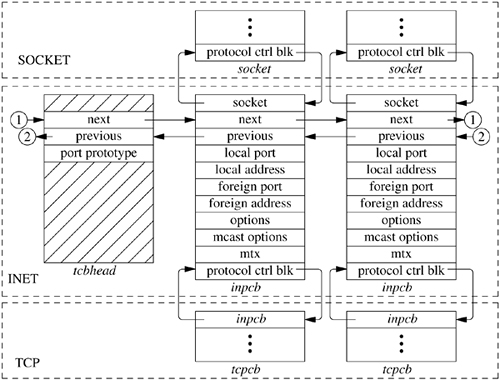
For each TCP- or UDP-based socket, an Internet protocol control block (an inpcb structure) is created to hold Internet network addresses, port numbers, routing information, and pointers to any auxiliary data structures. TCP, in addition, creates a TCP control block (a tcpcb structure) to hold the wealth of protocol state information necessary for its implementation. Internet control blocks for use with TCP are maintained on a doubly linked list private to the TCP protocol module. Internet control blocks for use with UDP are kept on a similar list private to the UDP protocol module. Two separate lists are needed because each protocol in the Internet domain has a distinct space of port identifiers. Common routines are used by the individual protocols to add new control blocks to a list, fix the local and remote parts of an association, locate a control block by association, and delete control blocks. IP demultiplexes message traffic based on the protocol identifier specified in its protocol header, and each higher-level protocol is then responsible for checking its list of Internet control blocks to direct a message to the appropriate socket. Figure 13.3 shows the linkage between the socket data structure and these protocol-specific data structures.
The implementation of the Internet protocols is tightly coupled, as befits the strong intertwining of the protocols. For example, the transport protocols send and receive packets including not only their own header, but also an IP pseudo-header containing the source and destination address, the protocol identifier, and a packet length. This pseudo-header is included in the transport-level packet checksum.
We are now ready to examine the operation of the Internet protocols. We begin with UDP, because it is far simpler than TCP.
The User Datagram Protocol (UDP) [Postel, 1980] is a simple, unreliable datagram protocol that provides only peer-to-peer addressing and optional data checksums. In FreeBSD, checksums are enabled or disabled on a systemwide basis and cannot be enabled or disabled on individual sockets. UDP protocol headers are extremely simple, containing only the source and destination port numbers, the datagram length, and the data checksum. The host addresses for a datagram are provided by the IP pseudo-header.
When a new datagram socket is created in the Internet domain, the socket layer locates the protocol-switch entry for UDP and calls the udp_attach() routine with the socket as a parameter. UDP uses in_pcballoc() to create a new protocol control block on its list of current sockets. It also sets the default limits for the socket send and receive buffers. Although datagrams are never placed in the send buffer, the limit is set as an upper limit on datagram size; the UDP protocol-switch entry contains the flag PR_ATOMIC, requiring that all data in a send operation be presented to the protocol at one time.
If the application program wishes to bind a port number—for example, the well-known port for some datagram service—it calls the bind system call. This request reaches UDP as a call to the udp_bind() routine. The binding may also specify a specific host address, which must be an address of an interface on this host. Otherwise, the address will be left unspecified, matching any local address on input, and with an address chosen as appropriate on each output operation. The binding is done by in_pcbbind(), which verifies that the chosen port number (or address and port) is not in use and then records the local part of the association.
To send datagrams, the system must know the remote part of an association. A program can specify this address and port with each send operation using sendto or sendmsg, or it can do the specification ahead of time with the connect system call. In either case, UDP uses the in_pcbconnect() function to record the destination address and port. If the local address was not bound, and if a route for the destination is found, the address of the outgoing interface is used as the local address. If no local port number was bound, one is chosen at this time.
A system call that sends data reaches UDP as a call to the udp_send() routine that takes a chain of mbufs containing the data for the datagram. If the call provided a destination address, the address is passed as well; otherwise, the address from a prior connect call is used. The actual output operation is done by udp_output(),
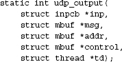
where inp is an IPv4 protocol control block, msg is chain of mbufs that contain the data to be sent, addr is an optional mbuf containing the destination address, and td is a pointer to a thread structure. Thread structures were discussed in Section 4.2 and are used within the network stack to identify the sender of a packet, which is why they are only used with output routines. Any ancillary data in control are discarded. The destination address could have been prespecified with a connect call; otherwise, it must be provided in the send call. UDP simply prepends its own header, fills in the UDP header fields and those of a prototype IP header, and calculates a checksum before passing the packet on to the IP module for output:
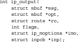
The call to IP's output routine is more complicated than UDP's because the IP routine needs to have more information specified about the endpoint to which it is communicating. The msg parameter indicates the message to be sent, and the opt parameter may specify a list of IP options that should be placed in the IP packet header. For multicast destinations, the into parameter may reference multicast options, such as the choice of interface and hop count for multicast packets. IP options may be set for a socket with the setsockopt system call specifying the IP protocol level and option IP_OPTIONS. These options are stored in a separate mbuf, and a pointer to this mbuf is stored in the protocol control block for a socket. The pointer to the options is passed to ip_output() with each packet sent. The ro parameter is optional and is passed as NULL by the udp_output() routine so that IP will determine a route for the packet. The flags parameter indicates whether the user is allowed to transmit a broadcast message and whether routing is to be bypassed for the message being sent (see Section 13.3). The broadcast flag may be inconsequential if the underlying hardware does not support broadcast transmissions. The flags also indicate whether the packet includes an IP pseudo-header or a completely initialized IP header, as when IP forwards packets.
All Internet transport protocols that are layered directly on top of IP use the following calling convention when receiving packets from IP:
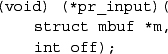
Each mbuf chain passed is a single packet to be processed by the protocol module. The packet includes the IP header in lieu of a pseudo-header, and the IP header length is passed as an offset: the second parameter. The UDP input routine udp_input() is typical of protocol input routines. It first verifies that the length of the packet is at least as long as the IP plus UDP headers, and it uses m_pullup() to make the header contiguous. The udp_input() routine then checks that the packet is the correct length and calculates a checksum for the data in the packet. If any of these tests fail, the packet is discarded, and error counts are increased. Any multicasting issues are handled next. Finally, the protocol control block for the socket that is to receive the data is located by in_pcblookup() using the addresses and port numbers in the packet. There might be multiple control blocks with the same local port number but different local or remote addresses; if so, the control block with the best match is selected. An exact association matches best, but if none exists, a socket with the correct local port number but unspecified local address, remote port number, or remote address will match. A control block with unspecified local or remote addresses thus acts as a wildcard that receives packets for its port if no exact match is found. If a control block is located, the data and the address from which the packet was received are placed in the receive buffer of the indicated socket with udp_append(). If the destination address is a multicast address, copies of the packet are delivered to each socket with matching addresses. Otherwise, if no receiver is found and if the packet was not addressed to a broadcast or multicast address, an ICMP port unreachable error message is sent to the originator of the datagram. This error message normally has no effect, as the sender typically connects to this destination only temporarily, and destroys the association before new input is processed. However, if the sender still has a fully specified association, it may receive notification of the error.
UDP supports no control operations and passes calls to its pr_ctloutput() entry directly to IP. It has a simple pr_ctlinput() routine that receives notification of any asynchronous errors. Errors are passed to any datagram socket with the indicated destination; only sockets with a destination fixed by a connect call may be notified of errors asynchronously. Such errors are simply noted in the appropriate socket, and socket wakeups are issued if the process is selecting or sleeping while waiting for input.
When a UDP datagram socket is closed, the udp_detach() routine is called. The protocol control block and its contents are simply deleted with in_pcbdetach(); no other processing is required.
Having examined the operation of a simple transport protocol, we continue with a discussion of the network-layer protocol [Postel, 1981a; Postel et al., 1981]. The Internet Protocol (IP) is the level responsible for host-to-host addressing and routing, packet forwarding, and packet fragmentation and reassembly. Unlike the transport protocols, it does not always operate for a socket on the local host; it may forward packets, receive packets for which there is no local socket, or generate error packets in response to these situations.
The functions done by IP are illustrated by the contents of its packet header, shown in Figure 13.4. The header identifies source and destination hosts and the destination protocol, and it contains header and packet lengths. The identification and fragment fields are used when a packet or fragment must be broken into smaller sections for transmission on its next hop and to reassemble the fragments when they arrive at the destination. The fragmentation flags are Don't Fragment and More Fragments; the latter flag plus the offset are enough information to assemble the fragments of the original packet at the destination.
Figure 13.4. IPv4 header. IHL is the Internet header length specified in units of four octets. Options are delimited by IHL. All field lengths are given in bits.
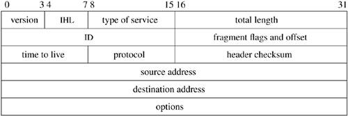
IP options are present in an IP packet if the header length field has a value larger than the minimum, which is 20 bytes. The no-operation option and the end-of-option-list option are each one octet in length. All other options are self-encoding, with a type and length preceding any additional data. Hosts and routers are thus able to skip over options that they do not implement. Examples of existing options are the timestamp and record-route options, which are updated by each router that forwards a packet, and the source-route options, which supply a complete or partial route to the destination.
In practice these are rarely used and most network operators silently drop packets with the source-route option because it makes it difficult to manage traffic on the network.
We have already seen the calling convention for the IP output routine, which is
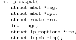
As described in the subsection on output in Section 13.2, the parameter msg is an mbuf chain containing the packet to be sent, including a skeletal IP header; opt is an optional mbuf containing IP options to be inserted after the header. If the route ro is given, it may contain a reference to a routing entry (rtentry structure), which specifies a route to the destination from a previous call, and in which any new route will be left for future use. Since cached routes were removed from the inpcb structure in FreeBSD 5.2, this cached route is seldomly used. The flags may allow the use of broadcast or may indicate that the routing tables should be bypassed. If present, imo includes options for multicast transmissions. The protocol control block, inp, is used by the IPSec subsystem (see Section 13.10) to hold data about security associations for the packet.
The outline of the work done by ip_output() is as follows:
- Insert any IP options.
- Fill in the remaining header fields (IP version, zero offset, header length, and a new packet identification) if the packet contains an IP pseudo-header.
- Determine the route (i.e., outgoing interface and next-hop destination).
- Check whether the destination is a multicast address. If it is, determine the outgoing interface and hop count.
- Check whether the destination is a broadcast address; if it is, check whether broadcast is permitted.
- Do any IPSec manipulations that are necessary on the packet such as encryption.
- See if there are any filtering rules that would modify the packet or prevent us from sending it.
- If the packet size is no larger than the maximum packet size for the outgoing interface, compute the checksum and call the interface output routine.
- If the packet size is larger than the maximum packet size for the outgoing interface, break the packet into fragments and send each in turn.
We shall examine the routing step in more detail. First, if no route reference is passed as a parameter, an internal routing reference structure is used temporarily. A route structure that is passed from the caller is checked to see that it is a route to the same destination and that it is still valid. If either test fails, the old route is freed. After these checks, if there is no route, rtalloc_ign() is called to allocate a route. The route returned includes a pointer to the outgoing interface. The interface information includes the maximum packet size, flags including broadcast and multicast capability, and the output routine. If the route is marked with the RTF_GATEWAY flag, the address of the next-hop router is given by the route; otherwise, the packet's destination is the next-hop destination. If routing is to be bypassed because of a MSG_DONTROUTE option (see Section 11.1) or a SO_DONTROUTE option, a directly attached network shared with the destination is sought; if there is no directly attached network, an error is returned. Once the outgoing interface and next-hop destination are found, enough information is available to send the packet.
As described in Chapter 12, the interface output routine normally validates the destination address and places the packet on its output queue, returning errors only if the interface is down, the output queue is full, or the destination address is not understood.
In Chapter 12, we described the reception of a packet by a network interface and the packet's placement on the input queue for the appropriate protocol. The network-interface handler then schedules the protocol to run by setting a corresponding bit in the network status word and scheduling the network thread. The IPv4 input routine is invoked via this software interrupt when network in`terfaces receive messages for the IPv4 protocol. The input routine, ip_input(), is called with an mbuf that contains the packet it is to process. The dequeueing of packets and the calls into the input routine are handled by the network thread calling netisr_dispatch(). A packet is processed in one of four ways: it is passed as input to a higher-level protocol, it encounters an error that is reported back to the source, it is dropped because of an error, or it is forwarded to the next hop on its path to its destination. In outline form, the steps in the processing of a packet on input are as follows:
- Verify that the packet is at least as long as an IPv4 header and ensure that the header is contiguous.
- Checksum the header of the packet and discard the packet if there is an error.
- Verify that the packet is at least as long as the header indicates and drop the packet if it is not. Trim any padding from the end of the packet.
- Do any filtering or security functions required by ipfw or IPSec.
- Process any options in the header.
- Check whether the packet is for this host. If it is, continue processing the packet. If it is not, and if acting as a router, try to forward the packet. Otherwise, drop the packet.
- If the packet has been fragmented, keep it until all its fragments are received and reassembled, or until it is too old to keep.
- Pass the packet to the input routine of the next-higher-level protocol.
When the incoming packet is passed into the input routine, it is accompanied by a pointer to the interface on which the packet was received. This information is passed to the next protocol, to the forwarding function, or to the error-reporting function. If any error is detected and is reported to the packet's originator, the source address of the error message will be set according to the packet's destination and the incoming interface.
The decision whether to accept a received packet for local processing by a higher-level protocol is not as simple as one might think. If a host has multiple addresses, the packet is accepted if its destination matches any one of those addresses. If any of the attached networks support broadcast and the destination is a broadcast address, the packet is also accepted.
The IPv4 input routine uses a simple and efficient scheme for locating the input routine for the receiving protocol of an incoming packet. The protocol field in the packet is 8 bits long; thus, there are 256 possible protocols. Fewer than 256 protocols are defined or implemented, and the Internet protocol switch has far fewer than 256 entries. Therefore, ip_input() uses a 256-element mapping array to map from the protocol number to the protocol-switch entry of the receiving protocol. Each entry in the array is initially set to the index of a raw IP entry in the protocol switch. Then, for each protocol with a separate implementation in the system, the corresponding map entry is set to the index of the protocol in the IP protocol switch. When a packet is received, IP simply uses the protocol field to index into the mapping array and calls the input routine of the appropriate protocol.
Implementations of IPv4 traditionally have been designed for use by either hosts or routers, rather than by both. That is, a system was either an endpoint for packets (as source or destination) or a router (which forwards packets between hosts on different networks but only uses upper-level protocols for maintenance functions). Traditional host systems do not incorporate packet-forwarding functions; instead, if they receive packets not addressed to them, they simply drop the packets. 4.2BSD was the first common implementation that attempted to provide both host and router services in normal operation. This approach had advantages and disadvantages. It meant that 4.2BSD hosts connected to multiple networks could serve as routers as well as hosts, reducing the requirement for dedicated router hardware. Early routers were expensive and not especially powerful. Alternatively, the existence of router-function support in ordinary hosts made it more likely for misconfiguration errors to result in problems on the attached networks. The most serious problem had to do with forwarding of a broadcast packet because of a misunderstanding by either the sender or the receiver of the packet's destination. The packet-forwarding router functions are disabled by default in FreeBSD. They may be enabled at run time with the sysctl call. Hosts not configured as routers never attempt to forward packets or to return error messages in response to misdirected packets. As a result, far fewer misconfiguration problems are capable of causing synchronized or repetitive broadcasts on a local network, called broadcast storms.
The procedure for forwarding IP packets received at a router but destined for another host is the following:
- Check that forwarding is enabled. If it is not, drop the packet.
- Check that the destination address is one that allows forwarding. Packets destined for network 0, network 127 (the official loopback network), or illegal network addresses cannot be forwarded.
- Save at most 64 octets of the received message in case an error message must be generated in response.
- Determine the route to be used in forwarding the packet.
- If the outgoing route uses the same interface as that on which the packet was received, and if the originating host is on that network, send an ICMP redirect message to the originating host. (ICMP is described in Section 13.8.)
- Handle any IPSec updates that must be made to the packet header.
- Call ip_output() to send the packet to its destination or to the next-hop gateway.
- If an error is detected, send an ICMP error message to the source host.
Multicast transmissions are handled separately from other packets. Systems may be configured as multicast routers independently from other routing functions. Multicast routers receive all incoming multicast packets, and forward those packets to local receivers and group members on other networks according to group memberships and the remaining hop count of incoming packets.
The most used protocol of the Internet protocol suite is the Transmission Control Protocol (TCP) [Cerf & Kahn, 1974; Postel, 1981b]. TCP is the reliable connection-oriented stream transport protocol on top of which most application protocols are layered. It includes several features not found in the other transport and network protocols described so far:
• Explicit and acknowledged connection initiation and termination
• Reliable, in-order, unduplicated delivery of data
• Flow control
• Out-of-band indication of urgent data
• Congestion avoidance
Because of these features, the TCP implementation is much more complicated than are those of UDP and IP. These complications, along with the prevalence of the use of TCP, make the details of TCP's implementation both more critical and more interesting than are the implementations of the simpler protocols. Figure 13.5 shows the flow of data through a TCP connection. We shall begin with an examination of the TCP itself and then continue with a description of its implementation in FreeBSD.
Figure 13.5. Data flow through a TCP/IP connection over an Ethernet. Key: ETHER—Ethernet header; PIP—pseudo-IP header; IP—IP header; TCP—TCP header; IF—interface.

A TCP connection may be viewed as a bidirectional, sequenced stream of data transferred between two peers. The data may be sent in packets of varying sizes and at varying intervals—for example, when they are used to support a login session over the network. The stream initiation and termination are explicit events at the start and end of the stream, and they occupy positions in the sequence space of the stream so that they can be acknowledged in the same way as data are. Sequence numbers are 32-bit numbers from a circular space; that is, comparisons are made modulo 232, so zero is the next sequence number after 232-l. The sequence numbers for each direction start with an arbitrary value, called the initial sequence number, sent in the initial packet for a connection. Following Bellovin [1996], the TCP implementation selects the initial sequence number by computing a function over the 4 tuple local port, foreign port, local address, foreign address that uniquely identifies the connection, and then adding a small offset based on the current time. This algorithm prevents the spoofing of TCP connections by an attacker guessing the next initial sequence number for a connection. This must be done while also guaranteeing that an old duplicate packet will not match the sequence space of a current connection.
Each packet of a TCP connection carries the sequence number of its first datum and (except during connection establishment) an acknowledgment of all contiguous data received. A TCP packet is known as a segment because it begins at a specific location in the sequence space and has a specific length. Acknowledgments are specified as the sequence number of the next sequence number not yet received. Acknowledgments are cumulative and thus may acknowledge data received in more than one (or part of one) packet. A packet may or may not contain data, but it always contains the sequence number of the next datum to be sent.
Flow control in TCP is done with a sliding-window scheme. Each packet with an acknowledgment contains a window, which is the number of octets of data that the receiver is prepared to accept, beginning with the sequence number in the acknowledgment. The window is a 16-bit field, limiting the window to 65535 octets by default; however, the use of a larger window may be negotiated. Urgent data are handled similarly; if the flag indicating urgent data is set, the urgent-data pointer is used as a positive offset from the sequence number of the packet to indicate the extent of urgent data. Thus, TCP can send notification of urgent data without sending all intervening data, even if the flow-control window would not allow the intervening data to be sent.
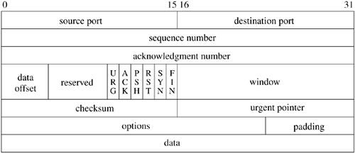
The complete header for a TCP packet is shown in Figure 13.6. The flags include SYN and FIN, denoting the initiation (synchronization) and completion of a connection. Each of these flags occupies a sequence space of one. A complete connection thus consists of a SYN, zero or more octets of data, and a FIN sent from each peer and acknowledged by the other peer. Additional flags indicate whether the acknowledgment field (ACK) and urgent fields (URG) are valid, and include a connection-abort signal (RST). Options are encoded in the same way as are IP options: The no-operation and end-of-options options are single octets, and all other options include a type and a length. The only option in the initial specification of TCP indicates the maximum segment (packet) size that a correspondent is willing to accept; this option is used only during initial connection establishment. Several other options have been defined. To avoid confusion, the protocol standard allows these options to be used in data packets only if both end-points include them during establishment of the connection.
The connection-establishment and connection-completion mechanisms of TCP are designed for robustness. They serve to frame the data that are transferred during a connection so that not only the data but also their extent are communicated reliably. In addition, the procedure is designed to discover old connections that have not terminated correctly because of a crash of one peer or loss of network connectivity. If such a half-open connection is discovered, it is aborted. Hosts choose new initial sequence numbers for each connection to lessen the chances that an old packet may be confused with a current connection.
The normal connection-establishment procedure is known as a three-way handshake. Each peer sends a SYN to the other, and each in turn acknowledges the other's SYN with an ACK. In practice, a connection is normally initiated by a client attempting to connect to a server listening on a well-known port. The client chooses a port number and initial sequence number and uses these selections in the initial packet with a SYN. The server creates a protocol control block for the pending connection and sends a packet with its initial sequence number, a SYN, and an ACK of the client's SYN. The client responds with an ACK of the server's SYN, completing connection establishment. As the ACK of the first SYN is piggybacked on the second SYN, this procedure requires three packets, leading to the term three-way handshake. The protocol still operates correctly if both peers attempt to start a connection simultaneously, although the connection setup requires four packets.
FreeBSD includes three options along with the SYN when initiating a connection. One contains the maximum segment size that the system is willing to accept [Jacobson et al., 1992]. The second of these options specifies a window-scaling value expressed as a binary shift value, allowing the window to exceed 65535 octets. If both peers include this option during the three-way handshake, both scaling values take effect; otherwise, the window value remains in octets. The third option is a timestamp option. If this option is sent in both directions during connection establishment, it will also be sent in each packet during data transfer. The data field of the timestamp option includes a timestamp associated with the current sequence number and also echoes a timestamp associated with the current acknowledgment. Like the sequence space, the timestamp uses a 32-bit field and modular arithmetic. The unit of the timestamp field is not defined, although it must fall between 1 millisecond and 1 second. The value sent by each system must be monotonically nondecreasing during a connection. FreeBSD uses the value of ticks, which is incremented at the system clock rate, HZ. These time-stamps can be used to implement round-trip timing. They also serve as an extension of the sequence space to prevent old duplicate packets from being accepted; this extension is valuable when a large window or a fast path, such as an Ethernet, is used.
After a connection is established, each peer includes an acknowledgment and window information in each packet. Each may send data according to the window that it receives from its peer. As data are sent by one end, the window becomes filled. As data are received by the peer, acknowledgments may be sent so that the sender can discard the data from its send queue. If the receiver is prepared to accept additional data, perhaps because the receiving process has consumed the previous data, it will also advance the flow-control window. Data, acknowledgments, and window updates may all be combined in a single message.
If a sender does not receive an acknowledgment within some reasonable time, it retransmits data that it presumes were lost. Duplicate data are discarded by the receiver but are acknowledged again in case the retransmission was caused by loss of the acknowledgment. If the data are received out of order, the receiver generally retains the out-of-order data for use when the missing segment is received. Out-of-order data cannot be acknowledged because acknowledgments are cumulative. A selective acknowledgment mechanism was introduced in Jacobson et al. [1992] but is not implemented in FreeBSD.
Each peer may terminate data transmission at any time by sending a packet with the FIN bit. A FIN represents the end of the data (like an end-of-file indication). The FIN is acknowledged, advancing the sequence number by 1. The connection may continue to carry data in the other direction until a FIN is sent in that direction. The acknowledgment of the FIN terminates the connection. To guarantee synchronization at the conclusion of the connection, the peer sending the last ACK of a FIN must retain state long enough that any retransmitted FIN packets would have reached it or have been discarded; otherwise, if the ACK were lost and a retransmitted FIN were received, the receiver would be unable to repeat the acknowledgment. This interval is arbitrarily set to twice the maximum expected segment lifetime (known as 2MSL).
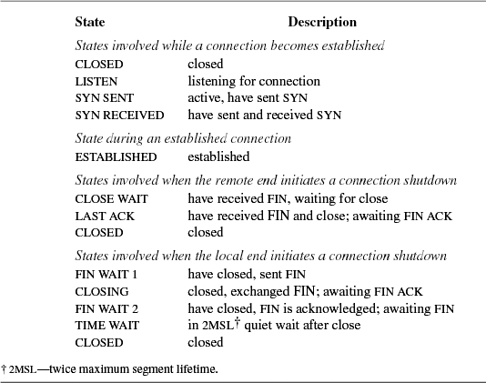
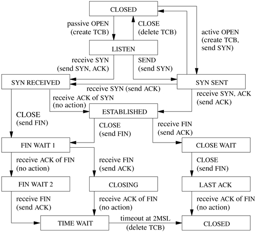
The TCP input-processing module and timer modules must maintain the state of a connection throughout that connection's lifetime. Thus, in addition to processing data received on the connection, the input module must process SYN and FIN flags and other state transitions. The list of states for one end of a TCP connection is given in Table 13.1. Figure 13.7 (on page 532) shows the finite-state machine made up by these states, the events that cause transitions, and the actions during the transitions.
If a connection is lost because of a crash or timeout on one peer but is still considered established by the other, then any data sent on the connection and received at the other end will cause the half-open connection to be discovered. When a half-open connection is detected, the receiving peer sends a packet with the RST flag and a sequence number derived from the incoming packet to signify that the connection is no longer in existence.
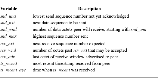
Each TCP connection maintains a large set of state variables in the TCP control block. This information includes the connection state, timers, options and state flags, a queue that holds data received out of order, and several sequence number variables. The sequence variables are used to define the send and receive sequence space, including the current window for each. The window is the range of data sequence numbers that are currently allowed to be sent, from the first octet of data not yet acknowledged up to the end of the range that has been offered in the window field of a header. The variables used to define the windows in FreeBSD are a superset of those used in the protocol specification [Postel, 1981b]. The send and receive windows are shown in Figure 13.8. The meanings of the sequence variables are listed in Table 13.2.
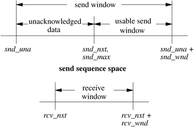
The area between snd_una and snd_una + snd_wnd is known as the send window. Data for the range snd_una to snd_max have been sent but not yet acknowledged and are kept in the socket send buffer along with data not yet transmitted. The snd_nxt field indicates the next sequence number to be sent and is incremented as data are transmitted. The area from snd_nxt to snd_una + snd_wnd is the remaining usable portion of the window, and its size determines whether additional data may be sent. The snd_nxt and snd_max values are normally maintained together except when TCP is retransmitting. The area between rcv_nxt and rcv_nxt + rcv_wnd is known as the receive window.
These variables are used in the output module to decide whether data can be sent, and in the input module to decide whether data that are received can be accepted. When the receiver detects that a packet is not acceptable because the data are all outside the window, it drops the packet but sends a copy of its most recent acknowledgment. If the packet contained old data, the first acknowledgment may have been lost, and thus it must be repeated. The acknowledgment also includes a window update, synchronizing the sender's state with the receiver's state.
If the TCP timestamp option is in use for the connection, the tests to see whether an incoming packet is acceptable are augmented with checks on the time-stamp. Each time that an incoming packet is accepted as the next expected packet, its timestamp is recorded in the ts_recent field in the TCP protocol control block. If an incoming packet includes a timestamp, the timestamp is compared to the most recently received timestamp. If the timestamp is less than the previous value, the packet is discarded as being an old duplicate and a current acknowledgment is sent in response. In this way, the timestamp serves as an extension to the sequence number, avoiding accidental acceptance of an old duplicate when the window is large or sequence numbers can be reused quickly. However, because of the granularity of the timestamp value, a timestamp received more than 24 days ago cannot be compared to a new value, and this test is bypassed. The current time is recorded when ts_recent is updated from an incoming timestamp to make this test. Of course, connections are seldom idle for longer than 24 days.
Now that we have introduced TCP, its state machine, and its sequence space, we can begin to examine the implementation of the protocol in FreeBSD. Several aspects of the protocol implementation depend on the overall state of a connection. The TCP connection state, output state, and state changes depend on external events and timers. TCP processing occurs in response to one of three events:
- A request from the user, such as sending data, removing data from the socket receive buffer, or opening or closing a connection
- The receipt of a packet for the connection
- The expiration of a timer
These events are handled in the routines tcp_usr_send(), tcp_input(), and a set of timer routines. Each routine processes the current event and makes any required changes in the connection state. Then, for any transition that may require sending a packet, the tcp_output() routine is called to do any output that is necessary.
The criteria for sending a packet with data or control information are complicated, and therefore the TCP send policy is the most interesting and important part of the protocol implementation. For example, depending on the state- and flow-control parameters for a connection, any of the following may allow data to be sent that could not be sent previously:
• A user send call that places new data in the send queue
• The receipt of a window update from the peer
• The expiration of the retransmission timer
• The expiration of the window-update (persist) timer
In addition, the tcp_output() routine may decide to send a packet with control information, even if no data may be sent, for any of these reasons:
• A change in connection state (e.g., open request, close request)
• Receipt of data that must be acknowledged
• A change in the receive window because of removal of data from the receive queue
• A send request with urgent data
• A connection abort
We shall consider most of these decisions in greater detail after we have described the states and timers involved. We begin with algorithms used for timing, connection setup, and shutdown; they are distributed through several parts of the code. We continue with the processing of new input and an overview of output processing and algorithms.
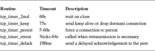
Unlike a UDP socket, a TCP connection maintains a significant amount of state information, and, because of that state, some operations must be done asynchronously. For example, data might not be sent immediately when a process presents them because of flow control. The requirement for reliable delivery implies that data must be retained after they are first transmitted so that they can be retransmitted if necessary. To prevent the protocol from hanging if packets are lost, each connection maintains a set of timers used to recover from losses or failures of the peer. These timers are stored in the protocol control block for a connection. The kernel provides a timer service via a set of callout() routines. The TCP module can register up to five timeout routines with the callout service, as shown in Table 13.3. Each routine has its own associated time at which it will be called. In earlier versions of BSD, timeouts were handled by the tcp_slowtimo() routine that was called every 500 milliseconds and would then do timer processing when necessary. Using the kernel's timer service is both more accurate, since each timer can be handled independently, and has less overhead, because no routine is called unless absolutely necessary.
Two timers are used for output processing. Whenever data are sent on a connection, the retransmit timer (tcp_rexmt()) is started by a call to callout_reset(), unless it is already running. When all outstanding data are acknowledged, the timer is stopped. If the timer expires, the oldest unacknowledged data are resent (at most one full-sized packet), and the timer is restarted with a longer value. The rate at which the timer value is increased (the timer backoff) is determined by a table of multipliers that provides an exponential increase in timeout values up to a ceiling.
The other timer used for maintaining output flow is the persist timer (tcp_timer_persist()) This timer protects against the other type of packet loss that could cause a connection to constipate: the loss of a window update that would allow more data to be sent. Whenever data are ready to be sent but the send window is too small to bother sending (zero, or less than a reasonable amount), and no data are already outstanding (the retransmit timer is not set), the persist timer is started. If no window update is received before the timer expires, the routine sends as large a segment as the window allows. If that size is zero, it sends a window probe (a single octet of data) and restarts the persist timer. If a window update was lost in the network, or if the receiver neglected to send a window update, the acknowledgment will contain current window information. On the other hand, if the receiver is still unable to accept additional data, it should send an acknowledgment for previous data with a still-closed window. The closed window might persist indefinitely; for example, the receiver might be a network-login client, and the user might stop terminal output and leave for lunch (or vacation).
The third timer used by TCP is a keepalive timer (tcp_timer_keep()) The keepalive timer has two different purposes at different phases of a connection. During connection establishment, this timer limits the time for the three-way handshake to complete. If the timer expires during connection setup, then the connection is closed. Once the connection completes, the keepalive timer monitors idle connections that might no longer exist on the peer because of a network partition or a crash. If a socket-level option is set and the connection has been idle since the most recent keepalive timeout, the timer routine will send a keepalive packet designed to produce either an acknowledgment or a reset (RST) from the peer TCP. If a reset is received, the connection will be closed; if no response is received after several attempts, the connection will be dropped. This facility is designed so that network servers can avoid languishing forever if the client disappears without closing. Keepalive packets are not an explicit feature of the TCP protocol. The packets used for this purpose by FreeBSD set the sequence number to 1 less than snd_una, which should elicit an acknowledgment from the peer if the connection still exists.
The fourth TCP timer is known as the 2MSL timer ("twice the maximum segment lifetime"). TCP starts this timer when a connection is completed by sending an acknowledgment for a FIN (from FIN_WAIT_2) or by receiving an ACK for a FIN (from CLOSING state, where the send side is already closed). Under these circumstances, the sender does not know whether the acknowledgment was received. If the FIN is retransmitted, it is desirable that enough state remain that the acknowledgment can be repeated. Therefore, when a TCP connection enters the TIME_WAIT state, the 2MSL timer is started; when the timer expires, the control block is deleted. If a retransmitted FIN is received, another ACK is sent, and the timer is restarted. To prevent this delay from blocking a process closing the connection, any process close request is returned successfully without the process waiting for the timer. Thus, a protocol control block may continue its existence even after the socket descriptor has been closed. In addition, FreeBSD starts the 2MSL timer when FIN_WAIT_2 state is entered after the user has closed; if the connection is idle until the timer expires, it will be closed. Because the user has already closed, new data cannot be accepted on such a connection in any case. This timer is set because certain other TCP implementations (incorrectly) fail to send a FIN on a receive-only connection. Connections to such hosts would remain in FIN_WAIT_2 state forever if the system did not have a timeout.
The final timer is the tcp_timer_delack(), which processes delayed acknowledgments. This will be described in Section 13.6.
When connections must traverse slow networks that lose packets, an important decision determining connection throughput is the value to be used when the retransmission timer is set. If this value is too large, data flow will stop on the connection for an unnecessarily long time before the dropped packet is resent. Another round-trip time interval is required for the sender to receive an acknowledgment of the resent segment and a window update, allowing it to send new data. (With luck, only one segment will have been lost, and the acknowledgment will include the other segments that had been sent.) If the timeout value is too small, however, packets will be retransmitted needlessly. If the cause of the network slowness or packet loss is congestion, then unnecessary retransmission only exacerbates the problem. The traditional solution to this problem in TCP is for the sender to estimate the round-trip time (rtt) for the connection path by measuring the time required to receive acknowledgments for individual segments. The system maintains an estimate of the round-trip time as a smoothed moving average, srtt [Postel, 1981b], using
In addition to a smoothed estimate of the round-trip time, TCP keeps a smoothed variance (estimated as mean difference, to avoid square-root calculations in the kernel). It employs an a value of 0.875 for the round-trip time and a corresponding smoothing factor of 0.75 for the variance. These values were chosen in part so that the system could compute the smoothed averages using shift operations on fixed-point values instead of floating-point values because on many hardware architectures it is expensive to use floating-point arithmetic. The initial retransmission timeout is then set to the current smoothed round-trip time plus four times the smoothed variance. This algorithm is substantially more efficient on long-delay paths with little variance in delay, such as satellite links, because it computes the BETA factor dynamically [Jacobson, 1988].
For simplicity, the variables in the TCP protocol control block allow measurement of the round-trip time for only one sequence value at a time. This restriction prevents accurate time estimation when the window is large; only one packet per window can be timed. However, if the TCP timestamps option is supported by both peers, a timestamp is sent with each data packet and is returned with each acknowledgment. Here, estimates of round-trip time can be obtained with each new acknowledgment; the quality of the smoothed average and variance is thus improved, and the system can respond more quickly to changes in network conditions.
There are two ways in which a new TCP connection can be established. An active connection is initiated by a connect call, whereas a passive connection is created when a listening socket receives a connection request. We consider each in turn.
The initial steps of an active connection attempt are similar to the actions taken during the creation of a UDP socket. The process creates a new socket, resulting in a call to the tcp_attach() routine. TCP creates an inpcb protocol control block and then creates an additional control block (a tcpcb structure), as described in Section 13.1. Some of the flow-control parameters in the tcpcb are initialized at this time. If the process explicitly binds an address or port number to the connection, the actions are identical to those for a UDP socket. Then a tcp_connect() call initiates the actual connection. The first step is to set up the association with in_pcbconnect(), again identically to this step in UDP. A packet-header template is created for use in construction of each output packet. An initial sequence number is chosen from a sequence-number prototype, which is then advanced by a substantial amount. The socket is then marked with soisconnecting(), the TCP connection state is set to TCPS_SYN_SENT, the keepalive timer is set (to 75 seconds) to limit the duration of the connection attempt, and tcp_output() is called for the first time.
The output-processing module tcp_output() uses an array of packet control flags indexed by the connection state to determine which control flags should be sent in each state. In the TCPS_SYN_SENT state, the SYN flag is sent. Because it has a control flag to send, the system sends a packet immediately using the prototype just constructed and including the current flow-control parameters. The packet normally contains three option fields: a maximum-segment-size option, a window-scale option, and a timestamps option (see Section 13.4). The maximum-segment-size option communicates the largest segment size that TCP is willing to accept. To compute this value, the system locates a route to the destination. If the route specifies a maximum transmission unit (MTU), the system uses that value after allowing for packet headers. If the connection is to a destination on a local network the maximum transmission unit of the outgoing network interface is used, possibly rounding down to a multiple of the mbuf cluster size for efficiency of buffering. If the destination is not local and nothing is known about the intervening path, the default segment size (512 octets) is used.
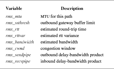
In earlier versions of FreeBSD many of the important variables relating to TCP connections, such as the MTU of the path between the two endpoints, and the data used to manage the connection were contained in the route entry that described the connection and in a routing entry as a set of route metrics. The TCP host cache was developed to centralize all this information in one easy-to-find place so that information that was gathered on one connection could be reused when a new connection was opened to the same endpoint. The data that is recorded on a connection is shown in Table 13.4. All the variables stored in a host cache entry are described in various parts of later sections of this chapter when they become relevant to our discussion of how TCP manages a connection.
Whenever a new connection is opened, a call is made to tcp_hc_get() to find any information on past connections. If an entry exists in the cache for the target endpoint, TCP uses the cached information to make better-informed decisions about managing the connection. When a connection is closed, the host cache is updated with all the relevant information that was discovered during the connection between the two hosts. Each host cache entry has a default lifetime of one hour. Anytime that the entry is accessed or updated, its lifetime is reset to one hour. Every five minutes the tcp_hc_purge() routine is called to clean out any entries that have passed their expiration time. Cleaning out old entries ensures that the host cache does not grow too large and that it always has reasonably fresh data.
TCP can use Path MTU Discovery as described in Mogul & Deering [1990]. Path MTU discovery is a process whereby the system probes the network to see what the maximum transfer unit is on a particular route between two nodes. It does this by sending packets with the IP flag don't fragment set on each packet. If the packet encounters a segment on its path to its destination on which it would have to be fragmented, then it is dropped by the intervening router, and an error is returned to the sender. The error message contains the maximum size packet that the segment will accept. This information is recorded in the TCP host cache for the appropriate endpoint and transmission is attempted with the smaller MTU. Once the connection is complete, because enough packets have made it through the network to establish a TCP connection, the revised MTU recorded in the host cache is confirmed. Packets will continue to be transmitted with the don't fragment flag set so that if the path to the node changes, and that path has an even smaller MTU, this new smaller MTU will be recorded. FreeBSD currently has no way of upgrading the MTU to a larger size when a route changes.
When a connection is first being opened, the retransmit timer is set to the default value (6 seconds) because no round-trip time information is available yet. With a bit of luck, a responding packet will be received from the target of the connection before the retransmit timer expires. If not, the packet is retransmitted and the retransmit timer is restarted with a greater value. If no response is received before the keepalive timer expires, the connection attempt is aborted with a "Connection timed out" error. If a response is received, however, it is checked for agreement with the outgoing request. It should acknowledge the SYN that was sent and should include a SYN. If it does both, the receive sequence variables are initialized, and the connection state is advanced to TCPS_ESTABLISHED. If a maximum-segment-size option is present in the response, the maximum segment size for the connection is set to the minimum of the offered size and the maximum transmission unit of the outgoing interface; if the option is not present, the default size (512 data bytes) is recorded. The flag TF_ACKNOW is set in the TCP control block before the output routine is called so that the SYN will be acknowledged immediately. The connection is now ready to transfer data.
The events that occur when a connection is created by a passive open are different. A socket is created and its address is bound as before. The socket is then marked by the listen call as willing to accept connections. When a packet arrives for a TCP socket in TOPS LISTEN state, a new socket is created with sonewconn(), which calls the TCP tcp_usr_attach() routine to create the protocol control blocks for the new socket. The new socket is placed on the queue of partial connections headed by the listening socket. If the packet contains a SYN and is otherwise acceptable, the association of the new socket is bound, both the send and the receive sequence numbers are initialized, and the connection state is advanced to TCPS_SYN_RECEIVED. The keepalive timer is set as before, and the output routine is called after TF_ACKNOW has been set to force the SYN to be acknowledged; an outgoing SYN is sent as well. If this SYN is acknowledged properly, the new socket is moved from the queue of partial connections to the queue of completed connections. If the owner of the listening socket is sleeping in an accept call or does a select, the socket will indicate that a new connection is available. Again, the socket is finally ready to send data. Up to one window of data may have already been received and acknowledged by the time that the accept call completes.
One problem in previous implementations of TCP was that it was possible for a malicious program to flood a system with SYN packets, thereby preventing it from doing any useful work or servicing any real connections. This type of denial of service attack became common during the commercialization of the Internet in the late 1990s. To combat this attack, a syncache was introduced to efficiently store, and possibly discard, SYN packets that do not lead to real connections. The syncache handles the three-way handshake between a local server and connecting peers.
When a SYN packet is received for a socket that is in the LISTEN state, the TCP module attempts to add a new syncache entry for the packet using the syncache_add() routine. If there are any data in the received packet, they are not acknowledged at this time. Acknowledging the data would use up system resources, and an attacker could exhaust these resources by flooding the system with SYN packets that included data. If this SYN has not been seen before, a new entry is created in the hash table based on the packet's foreign address, foreign port, the local port of the socket, and a mask. The syncache module responds to the SYN with a SYN/ACK and sets a timer on the new entry. If the syncache contains an entry that matches the received packet, then it is assumed that the original SYN/ACK was not received by the peer initiating the connection, and another SYN/ACK is sent and the timer on the syncache entry is reset. There is no limit set on the number of SYN packets that can be sent by a connecting peer. Any limit would not follow the TCP RFCs and might impede connections over lossy networks.
A TCP connection is symmetrical and full-duplex, so either side may initiate disconnection independently. As long as one direction of the connection can carry data, the connection remains open. A socket may indicate that it has completed sending data with the shutdown system call, which results in a call to the tcp_usr_shutdown() routine. The response to this request is that the state of the connection is advanced; from the ESTABLISHED state, the state becomes FIN_WAIT_1. The ensuing output call will send a FIN, indicating an end-of-file. The receiving socket will advance to CLOSE_WAIT but may continue to send. The procedure may be different if the process simply closes the socket. In that case, a FIN is sent immediately, but if new data are received, they cannot be delivered. Normally, higher-level protocols conclude their own transactions such that both sides know when to close. If they do not, however, TCP must refuse new data. It does so by sending a packet with the RST flag set if new data are received after the user has closed. If data remain in the send buffer of the socket when the close is done, TCP will normally attempt to deliver them. If the socket option SO_LINGER was set with a linger time of zero, the send buffer is simply flushed; otherwise, the user process is allowed to continue, and the protocol waits for delivery to conclude. Under these circumstances, the socket is marked with the state bit SS_NOFDREF (no file-descriptor reference). The completion of data transfer and the final close can take place an arbitrary amount of time later. When TCP finally completes the connection (or gives up because of timeout or other failure), it calls tcp_close(). The protocol control blocks and other dynamically allocated structures are freed at this time. The socket also is freed if the SS_NOFDREF flag has been set. Thus, the socket remains in existence as long as either a file descriptor or a protocol control block refers to it.
Although TCP input processing is considerably more complicated than UDP input handling, the preceding sections have provided the background that we need to examine the actual operation. As always, the input routine is called with parameters
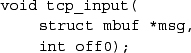
The first few steps probably are beginning to sound familiar:
- Locate the TCP header in the received IP datagram. Make sure that the packet is at least as long as a TCP header, and use m_pullup() if necessary to make it contiguous.
- Compute the packet length, set up the IP pseudo-header, and checksum the TCP header and data. Discard the packet if the checksum is bad.
- Check the TCP header length; if it is larger than a minimal header, make sure that the whole header is contiguous.
- Locate the protocol control block for the connection with the port number specified. If none exists, send a packet containing the reset flag RST and drop the packet.
- Check whether the socket is listening for connections; if it is, follow the procedure described for passive connection establishment.
- Process any TCP options from the packet header.
- Clear the idle time for the connection, and set the keepalive timer to its normal value.
At this point, the normal checks have been made, and we are prepared to deal with data and control flags in the received packet. There are still many consistency checks that must be made during normal processing; for example, the SYN flag must be present if we are still establishing a connection and must not be present if the connection has been established. We shall omit most of these checks from our discussion, but the tests are important to prevent wayward packets from causing confusion and possible data corruption.
The next step in checking a TCP packet is to see whether the packet is acceptable according to the receive window. It is important that this step be done before control flags—in particular RST—are examined because old or extraneous packets should not affect the current connection unless they are clearly relevant in the current context. A segment is acceptable if the receive window has nonzero size and if at least some of the sequence space occupied by the packet falls within the receive window. If the packet contains data, some of the data must fall within the window. Portions of the data that precede the window are trimmed, since they have already been received, and portions that exceed the window also are discarded, since they have been sent prematurely. If the receive window is closed (rcv_wrul is zero), then only segments with no data and with a sequence number equal to rcv_nxt are acceptable. If an incoming segment is not acceptable, it is dropped after an acknowledgment is sent.
The processing of incoming TCP packets must be fully general, taking into account all the possible incoming packets and possible states of receiving end-points. However, the bulk of the packets processed falls into two general categories. Typical packets contain either the next expected data segment for an existing connection or an acknowledgment plus a window update for one or more data segments, with no additional flags or state indications. Rather than considering each incoming segment based on first principles, tcp_input() checks first for these common cases. This algorithm is known as header prediction. If the incoming segment matches a connection in the ESTABLISHED state, if it contains the ACK flag but no other flags, if the sequence number is the next value expected (and the timestamp, if any, is nondecreasing), if the window field is the same as in the previous segment, and if the connection is not in a retransmission state, then the incoming segment is one of the two common types. The system processes any timestamp option that the segment contains, recording the value received to be included in the next acknowledgment. If the segment contains no data, it is a pure acknowledgment with a window update. In the usual case, round-trip-timing information is sampled if it is available, acknowledged data are dropped from the socket send buffer, and the sequence values are updated. The packet is discarded once the header values have been checked. The retransmit timer is canceled if all pending data have been acknowledged; otherwise, it is restarted. The socket layer is notified if any process might be waiting to do output. Finally, tcp_output() is called because the window has moved forward, and that operation completes the handling of a pure acknowledgment.
If a packet meeting the tests for header prediction contains the next expected data, if no out-of-order data are queued for the connection, and if the socket receive buffer has space for the incoming data, then this packet is a pure insequence data segment. The sequencing variables are updated, the packet headers are removed from the packet, and the remaining data are appended to the socket receive buffer. The socket layer is notified so that it can notify any interested thread, and the control block is marked with a flag, indicating that an acknowledgment is needed. No additional processing is required for a pure data packet.
For packets that are not handled by the header-prediction algorithm, the processing steps are as follows:
- Process the timestamp option if it is present, rejecting any packets for which the timestamp has decreased, first sending a current acknowledgment.
- Check whether the packet begins before rcv_nxt. If it does, ignore any SYN in the packet, and trim any data that fall before rcv_nxt. If no data remain, send a current acknowledgment and drop the packet. (The packet is presumed to be a duplicate transmission.)
- If the packet still contains data after trimming, and the process that created the socket has already closed the socket, send a reset (RST) and drop the connection. This reset is necessary to abort connections that cannot complete; it typically is sent when a remote-login client disconnects while data are being received.
- If the end of the segment falls after the window, trim any data beyond the window. If the window was closed and the packet sequence number is rcv_nxt, the packet is treated as a window probe; TF_ACKNOW is set to send a current acknowledgment and window update, and the remainder of the packet is processed. If SYN is set and the connection was in TIME_WAIT state, this packet is really a new connection request, and the old connection is dropped; this procedure is called rapid connection reuse. Otherwise, if no data remain, send an acknowledgment and drop the packet.
The remaining steps of TCP input processing check the following flags and fields and take the appropriate actions: RST, ACK, window, URG, data, and FIN. Because the packet has already been confirmed to be acceptable, these actions can be done in a straightforward way:
- If a timestamp option is present, and the packet includes the next sequence number expected, record the value received to be included in the next acknowledgment.
- If RST is set, close the connection and drop the packet.
- If ACK is not set, drop the packet.
- If the acknowledgment-field value is higher than that of previous acknowledgments, new data have been acknowledged. If the connection was in SYN_RECEIVED state and the packet acknowledges the SYN sent for this connection, enter ESTABLISHED state. If the packet includes a timestamp option, use it to compute a round-trip time sample; otherwise, if the sequence range that was newly acknowledged includes the sequence number for which the round-trip time was being measured, this packet provides a sample. Average the time sample into the smoothed round-trip time estimate for the connection. If all outstanding data have been acknowledged, stop the retransmission timer; otherwise, set it back to the current timeout value. Finally, drop from the send queue in the socket the data that were acknowledged. If a FIN has been sent and was acknowledged, advance the state machine.
- Check the window field to see whether it advances the known send window. First, check whether this packet is a new window update. If the sequence number of the packet is greater than that of the previous window update, or the sequence number is the same but the acknowledgment-field value is higher, or if both sequence and acknowledgment are the same but the window is larger, record the new window.
- If the urgent-data flag URG is set, compare the urgent pointer in the packet to the last-received urgent pointer. If it is different, new urgent data have been sent. Use the urgent pointer to compute so_oobmark, the offset from the beginning of the socket receive buffer to the urgent mark (Section 11.6), and notify the socket with sohasoutofband(). If the urgent pointer is less than the packet length, the urgent data have all been received. TCP normally removes the final data octet sent in urgent mode (the last octet before the urgent pointer) and places that octet in the protocol control block until it is requested with a PRU_RCVOOB request. (The end of the urgent data is a subject of disagreement; the BSD interpretation follows the original TCP specification.) A socket option, SO_OOBINLINE, may request that urgent data be left in the queue with the normal data, although the mark on the data stream is still maintained.
- At long last, examine the data field in the received packet. If the data begin with rcv_nxt, then they can be placed directly into the socket receive buffer with sbappendstream(). The flag TF_DELACK is set in the protocol control block to indicate that an acknowledgment is needed, but the latter is not sent immediately in hope that it can be piggybacked on any packets sent soon (presumably in response to the incoming data) or combined with acknowledgment of other data received soon; see the subsection on delayed acknowledgments and window updates in Section 13.7. If no activity causes a packet to be returned before the next time that the tcp_delack() routine runs, it will change the flag to TF_ACKNOW and call the tcp_output() routine to send the acknowledgment. Acknowledgments can thus be delayed by no more than 200 milliseconds. If the data do not begin with rcv_nxt, the packet is retained in a per-connection queue until the intervening data arrive, and an acknowledgment is sent immediately.
- As the final step in processing a received packet, check for the FIN flag. If it is present, the connection state machine may have to be advanced, and the socket is marked with socantrcvmore() to convey the end-of-file indication. If the send side has already closed (a FIN was sent and acknowledged), the socket is now considered closed, and it is so marked with soisdisconnected(). The TF_ACKNOW flag is set to force immediate acknowledgment.
Step 10 completes the actions taken when a new packet is received by tcp_input(). However, as noted earlier in this section, receipt of input may require new output. In particular, acknowledgment of all outstanding data or a new window update requires either new output or a state change by the output module. Also, several special conditions set the TF_ACKNOW flag. In these cases, tcp_output() is called at the conclusion of input processing.
We are finally ready to investigate the most interesting part of the TCP implementation: the send policy. As we saw earlier, a TCP packet contains an acknowledgment and a window field as well as data, and a single packet may be sent if any of these three fields change. A naive TCP send policy might send many more packets than necessary. For example, consider what happens when a user types one character to a remote-terminal connection that uses remote echo. The server-side TCP receives a single-character packet. It might send an immediate acknowledgment of the character. Then, milliseconds later, the login server would read the character, removing the character from the receive buffer; the TCP might immediately send a window update, noting that one additional octet of send window was available. After another millisecond or so, the login server would send an echoed character back to the client, necessitating a third packet sent in response to the single character of input. It is obvious that all three responses (the acknowledgment, the window update, and the data return) could be sent in a single packet. However, if the server were not echoing input data, the acknowledgment could not be withheld for too long a time or the client-side TCP would begin to retransmit. The algorithms used in the send policy to minimize network traffic yet to maximize throughput are the most subtle part of a TCP implementation. The send policy used in FreeBSD includes several standard algorithms, as well as a few approaches suggested by the network research community. We shall examine each part of the send policy.
As we saw in the previous section, there are several different events that may trigger the sending of data on a connection; in addition, packets must be sent to communicate acknowledgments and window updates (consider a one-way connection!).
The most obvious reason that the tcp output module tcp_output() is called is that the user has written new data to the socket. Write operations are done with a call to tcp_usr_send() routine. (Recall that sosend() waits for enough space in the socket send buffer if necessary and then copies the user's data into a chain of mbufs that is passed to the protocol by the tcp_usr_send() routine.) The action in tcp_usr_send() is simply to place the new output data in the socket's send buffer with sbappendstream() and to call tcp_output(). If flow control permits, tcp_output() will send the data immediately.
The actual send operation is not substantially different from one for a UDP datagram socket. The differences are that the header is more complicated and additional fields must be initialized, and the data sent are simply a copy of the user's data. However, for send operations large enough for sosend() to place the data in external mbuf clusters, the copy is done by creating a new reference to the data cluster. A copy must be retained in the socket's send buffer in case retransmission is required. Also, if the number of data octets is larger than the size of a single maximum-sized segment, multiple packets will be constructed and sent in a single call.
The tcp_output() routine allocates an mbuf to contain the output packet header and copies the contents of the header template into that mbuf. If the data to be sent fit into the same mbuf as the header, tcp_output() copies them into place from the socket send buffer using the m_copydata() routine. Otherwise, tcp_output() adds the data to be sent as a separate chain of mbufs obtained with an m_copy() operation from the appropriate part of the send buffer. The sequence number for the packet is set from snd_nxt, and the acknowledgment is set from rcv_nxt. The flags are obtained from an array containing the flags to be sent in each connection state. The window to be advertised is computed from the amount of space remaining in the socket's receive buffer; however, if that amount is small (less than one-fourth of the buffer and less than one segment), it is set to zero. The window is never allowed to end at a smaller sequence number than the one in which it ended in the previous packet. If urgent data have been sent, the urgent pointer and flag are set accordingly. One other flag must be set: The PUSH flag on a packet indicates that data should be passed to the user; it is like a buffer-flush request. This flag is generally considered obsolete but is set whenever all the data in the send buffer have been sent; FreeBSD ignores this flag on input. Once the header is filled in, the packet is checksummed. The remaining parts of the IP header are initialized, including the type-of-service and time-to-live fields, and the packet is sent with ip_output(). The retransmission timer is started if it is not already running, and the snd_nxt and snd_max values for the connection are updated.
Silly-window syndrome is the name given to a potential problem in a window-based flow-control scheme in which a system sends several small packets rather than waiting for a reasonable-sized window to become available [Clark, 1982]. For example, if a network-login client program has a total receive buffer size of 4096 octets, and the user stops terminal output during a large printout, the buffer will become nearly full as new full-sized segments are received. If the remaining buffer space dropped to 10 bytes, it would not be useful for the receiver to volunteer to receive an additional 10 octets. If the user then allowed a few characters to print and stopped output again, it still would not be useful for the receiving TCP to send a window update allowing another 14 octets. Instead, it is desirable to wait until a reasonably large packet can be sent, since the receive buffer already contains enough data for the next several pages of output. Avoidance of the silly-window syndrome is desirable in both the receiver and the sender of a flow-controlled connection, as either end can prevent silly small windows from being used. We described receiver avoidance of the silly-window syndrome in the previous subsection; when a packet is sent, the receive window is advertised as zero if it is less than one packet and less than one-fourth of the receive buffer. For sender avoidance of the silly-window syndrome, an output operation is delayed if at least a full packet of data is ready to be sent but less than one full packet can be sent because of the size of the send window. Instead of sending, tcp_output() sets the output state to persist state by starting the persist timer. If no window update has been received by the time that the timer expires, the allowable data are sent in the hope that the acknowledgment will include a larger window. If it does not, the connection stays in persist state, sending a window probe periodically until the window is opened.
An initial implementation of sender avoidance of the silly-window syndrome produced large delays and low throughput over connections to hosts using TCP implementations with tiny buffers. Unfortunately, those implementations always advertised receive windows less than the maximum segment size—a behavior that was considered silly by this implementation. As a result of this problem, the TCP keeps a record of the largest receive window offered by a peer in the protocol-control-block variable max_sndwnd. When at least one-half of max_sndwnd may be sent, a new segment is sent. This technique improved performance when a BSD system was communicating with these limited hosts.
Network traffic exhibits a bimodal distribution of sizes. Bulk data transfers tend to use the largest possible packets for maximum throughput. Interactive services (such as network-login) tend to use small packets, however, often containing only a single data character. On a fast local-area network, such as an Ethernet, the use of single-character packets generally is not a problem because the network bandwidth usually is not saturated. On long-haul networks interconnected by slow or congested links, or wireless LANs that are both slow and lossy, it is desirable to collect input over some period and then send it in a single network packet. Various schemes have been devised for collecting input over a fixed time—usually about 50 to 100 milliseconds—and then sending it in a single packet. These schemes noticeably slow character echo times on fast networks, however, and often save few packets on slow networks. In contrast, a simple and elegant scheme for reducing small-packet traffic was suggested by Nagle [1984]. This scheme allows the first octet output to be sent alone in a packet with no delay. Until this packet is acknowledged, however, no new small packets may be sent. If enough new data arrive to fill a maximum-sized packet, another packet is sent. As soon as the outstanding data are acknowledged, the input that was queued while waiting for the first packet may be sent. Only one small packet may ever be outstanding on a connection at one time. The net result is that data from small output operations are queued during one round-trip time. If the round-trip time is less than the intercharacter arrival time, as it is in a remote-terminal session on a local-area network, transmissions are never delayed, and response time remains low. When a slow network intervenes, input after the first character is queued, and the next packet contains the input received during the preceding round-trip time. This algorithm is attractive because of both its simplicity and its self-tuning nature.
Eventually, people discovered that this algorithm did not work well for certain classes of network clients that sent streams of small requests that could not be batched. One such client was the network-based X Window System [Scheifler & Gettys, 1986], which required immediate delivery of small messages to get real-time feedback for user interfaces such as rubber-banding to sweep out a new window. Hence, the developers added an option, TCP_NODELAY, to defeat this algorithm on a connection. This option can be set with a setsockopt call, which reaches TCP via the tcp_ctloutput() routine. Unfortunately, the X Window System library always sets the TCP_NODELAY flag, rather than only when the client is using mouse-driven positioning.
TCP packets must be sent for reasons other than data transmission. On a one-way connection, the receiving TCP must still send packets to acknowledge received data and to advance the sender's send window. The mechanism for delaying acknowledgments in hope of piggybacking or coalescing them with data or window updates was described in Section 13.6. In a bulk data transfer, the time at which window updates are sent is a determining factor for network throughput. For example, if the receiver simply set the TF_DELACK flag each time that data were received on a bulk-data connection, acknowledgments would be sent every 200 milliseconds. If 8192-octet windows are used on a 10-Mbit/s Ethernet, this algorithm will result in a maximum throughput of 320 Kbit/s, or 3.2 percent of the physical network bandwidth. Clearly, once the sender has filled the send window that it has been given, it must stop until the receiver acknowledges the old data (allowing them to be removed from the send buffer and new data to replace them) and provides a window update (allowing the new data to be sent).
Because TCP's window-based flow control is limited by the space in the socket receive buffer, TCP has the PR_RCVD flag set in its protocol-switch entry so that the protocol will be called (via the tcp_usr_rcvd() routine) when the user has done a receive call that has removed data from the receive buffer. The tcp_usr_rcvd() routine simply calls tcp_output(). Whenever tcp_output() determines that a window update sent under the current circumstances would provide a new send window to the sender large enough to be worthwhile, it sends an acknowledgment and window update. If the receiver waited until the window was full, the sender would already have been idle for some time when it finally received a window update. Furthermore, if the send buffer on the sending system was smaller than the receiver's buffer—and thus smaller than the receiver's window—the sender would be unable to fill the receiver's window without receiving an acknowledgment. Therefore, the window-update strategy in FreeBSD is based on only the maximum segment size. Whenever a new window update would move the window forward by at least two full-sized segments, the window update is sent. This window-update strategy produces a twofold reduction in acknowledgment traffic and a twofold reduction in input processing for the sender. However, updates are sent often enough to give the sender feedback on the progress of the connection and to allow the sender to continue sending additional segments.
Note that TCP is called at two different stages of processing on the receiving side of a bulk data transfer: It is called on packet reception to process input, and it is called after each receive operation removing data from the input buffer. At the first call, an acknowledgment could be sent, but no window update could be sent. After the receive operation, a window update also is possible. Thus, it is important that the algorithm for updates run in the second half of this cycle.
When the retransmit timer expires while a sender is awaiting acknowledgment of transmitted data, tcp_output() is called to retransmit. The retransmit timer is first set to the next multiple of the round-trip time in the backoff series. The variable snd_nxt is moved back from its current sequence number to snd_una. A single packet is then sent containing the oldest data in the transmit queue. Unlike some other systems, FreeBSD does not keep copies of the packets that have been sent on a connection; it retains only the data. Thus, although only a single packet is retransmitted, that packet may contain more data than does the oldest outstanding packet. On a slow connection with small send operations, such as a remote login, this algorithm may cause a single-octet packet that is lost to be retransmitted with all the data queued since the initial octet was first transmitted.
If a single packet was lost in the network, the retransmitted packet will elicit an acknowledgment of all data transmitted thus far. If more than one packet was lost, the next acknowledgment will include the retransmitted packet and possibly some of the intervening data. It may also include a new window update. Thus, when an acknowledgment is received after a retransmit timeout, any old data that were not acknowledged will be resent as though they had not yet been sent, and some new data may be sent as well.
Many TCP connections traverse several networks between source and destination. When some of the networks are slower than others, the entry router to the slowest network often is presented with more traffic than it can handle. It may buffer some input packets to avoid dropping them because of sudden changes in flow, but eventually its buffers will fill and it must begin dropping packets. When a TCP connection first starts sending data across a fast network to a router forwarding via a slower network, it may find that the router's queues are already nearly full. In the original send policy used in BSD, a bulk-data transfer would start out by sending a full window of packets once the connection was established. These packets could be sent at the full speed of the network to the bottleneck router, but that router could transmit them only at a much slower rate. As a result, the initial burst of packets was highly likely to overflow the router's queue, and some of the packets would be lost. If such a connection used an expanded window size in an attempt to gain performance—for example, when traversing a satellite-based network with a long round-trip time—this problem would be even more severe. However, if the connection could once reach steady state, a full window of data often could be accommodated by the network if the packets were spread evenly throughout the path. At steady state, new packets would be injected into the network only when previous packets were acknowledged, and the number of packets in the network would be constant. Figure 13.9 shows the desired steady state. In addition, even if packets arrived at the outgoing router in a cluster, they would be spread out when the network was traversed by at least their transmission times in the slowest network. If the receiver sent acknowledgments when each packet was received, the acknowledgments would return to the sender with approximately the correct spacing. The sender would then have a self-clocking means for transmitting at the correct rate for the network without sending bursts of packets that the bottleneck could not buffer.
Figure 13.9. Acknowledgment clocking. There are two routers connected by a slow link between the sender and the receiver. The thickness of the links represents their speed. The width of the packets represents their time to travel down the link. Fast links are wide and the packets are narrow. Slow links are narrow and the packets are wide. In the steady state shown, the sender sends a new packet each time an acknowledgment is received from the receiver.
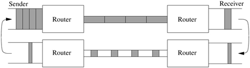
An algorithm named slow start brings a TCP connection to this steady state [Jacobson, 1988]. It is called slow start because it is necessary to start data transmission slowly when traversing a slow network. Figure 13.10 shows the progress of the slow-start algorithm. The scheme is simple: A connection starts out with a limit of just one outstanding packet. Each time that an acknowledgment is received, the limit is increased by one packet. If the acknowledgment also carries a window update, two packets can be sent in response. This process continues until the window is fully open. During the slow-start phase of the connection, if each packet was acknowledged separately, the limit would be doubled during each exchange, resulting in an exponential opening of the window. Delayed acknowledgments might cause acknowledgments to be coalesced if more than one packet could arrive at the receiver within 200 milliseconds, slowing the window opening slightly. However, the sender never sends bursts of more than two or three packets during the opening phase and sends only one or two packets at a time once the window has opened.
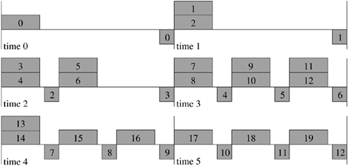
The implementation of the slow-start algorithm uses a second window, like the send window but maintained separately, called the congestion window (snd_cwnd). The congestion window is maintained according to an estimate of the data that the network is currently able to buffer for this connection. The send policy is modified so that new data are sent only if allowed by both the normal and congestion send windows. The congestion window is initialized to the size of one packet, causing a connection to begin with a slow start. It is set to one packet whenever transmission stops because of a timeout. Otherwise, once a retransmitted packet was acknowledged, the resulting window update might allow a full window of data to be sent, which would once again overrun intervening routers. This slow start after a retransmission timeout eliminates the need for a test in the output routine to limit output to one packet on the initial timeout. In addition, the timeout may indicate that the network has become slower because of congestion, and temporary reduction of the window may help the network to recover from its condition. The connection is forced to reestablish its clock of acknowledgments after the connection has come to a halt, and the slow start has this effect as well. A slow start is also forced if a connection begins to transmit after an idle period of at least the current retransmission value (a function of the smoothed round-trip time and variance estimates).
If a router along the route used by a connection receives more packets than it can send along this path, it will eventually be forced to drop packets. When packets are dropped, the router may send an ICMP source quench error message to hosts whose packets have been dropped to indicate that the senders should slow their transmissions. Although this message indicates that some change should be made, it provides no information on how much of a change must be made or for how long the change should take effect. In addition, not all routers send source-quench messages for each packet dropped. The use of the slow-start algorithm after retransmission timeouts allows a connection to respond correctly to a dropped packet whether or not a source quench is received to indicate the loss. The action on receipt of a source quench for a TCP connection is simply to anticipate the timeout because of the dropped packet, setting the congestion window to one packet. This action prevents new packets from being sent until the dropped packet is resent at the next timeout. At that time, the slow start will begin again.
The performance of a TCP connection is obviously limited by the bandwidth of the path that the connection must transit. The performance is also affected by the round-trip time for the path. For example, paths that traverse satellite links have a long intrinsic delay, even though the bandwidth may be high, but the throughput is limited to one window of data per round-trip time. After filling the receiver's window, the sender must wait for at least one round-trip time for an acknowledgment and window update to arrive. To take advantage of the full bandwidth of a path, both the sender and receiver must use buffers at least as large as the bandwidth-delay product to allow the sender to transmit during the entire round-trip time. In steady state, this buffering allows the sender, receiver, and intervening parts of the network to keep the pipeline filled at each stage. For some paths, using slow start and a large window can lead to much better performance than could be achieved previously.
The round-trip time for a network path includes two components: transit time and queueing time. The transit time comprises the propagation, switching, and forwarding time in the physical layers of the network, including the time to transmit packets bit by bit after each store-and-forward hop. Ideally, queueing time would be negligible, with packets arriving at each node of the network just in time to be sent after the preceding packet. This ideal flow is possible when a single connection using a suitable window size is synchronized with the network. However, as additional traffic is injected into the network by other sources, queues build up in routers, especially at the entrance to the slower links in the path. Although queueing delay is part of the round-trip time observed by each network connection that is using a path, it is not useful to increase the operating window size for a connection to a value larger than the product of the limiting bandwidth for the path times the transit delay. Sending additional data beyond that limit causes the additional data to be queued, increasing queueing delay without increasing throughput.
The addition of the slow-start algorithm to TCP allows a connection to send packets at a rate that the network can tolerate, reaching a steady state at which packets are sent only when another packet has exited the network. A single connection may reasonably use a large window without flooding the entry router to the slow network on startup. As a connection opens the window during a slow start, it injects packets into the network until the network links are kept busy. During this phase, it may send packets at up to twice the rate at which the network can deliver data because of the exponential opening of the window. If the window is chosen appropriately for the path, the connection will reach steady state without flooding the network. However, with multiple connections sharing a path, the bandwidth available to each connection is reduced. If each connection uses a window equal to the bandwidth-delay product, the additional packets in transit must be queued, increasing delay. If the total offered load is too high, routers must drop packets rather than increasing the queue sizes and delay. Thus, the appropriate window size for a TCP connection depends not only on the path, but also on competing traffic. A window size large enough to give good performance when a long-delay link is in the path will overrun the network when most of the round-trip time is in queueing delays. It is highly desirable for a TCP connection to be self-tuning, as the characteristics of the path are seldom known at the endpoints and may change with time. If a connection expands its window to a value too large for a path, or if additional load on the network collectively exceeds the capacity, router queues will build until packets must be dropped. At this point, the connection will close the congestion window to one packet and will initiate a slow start. If the window is simply too large for the path, however, this process will repeat each time that the window is opened too far.
The connection can learn from this problem and can adjust its behavior using another algorithm associated with the slow-start algorithm. This algorithm keeps a state variable for each connection, snd_ssthresh (slow-start threshold), which is an estimate of the usable window for the path. When a packet is dropped, as evidenced by a retransmission timeout, this window estimate is set to one-half the number of the outstanding data octets. The current window is obviously too large at the moment, and the decrease in window utilization must be large enough that congestion will decrease rather than stabilizing. At the same time, the slow-start window (snd_cwnd) is set to one segment to restart. The connection starts up as before, opening the window exponentially until it reaches the snd_ssthresh limit. At this point, the connection is near the estimated usable window for the path. It enters steady state, sending data packets as allowed by window updates. To test for improvement in the network, it continues to expand the window slowly; as long as this expansion succeeds, the connection can continue to take advantage of reduced network load. The expansion of the window in this phase is linear, with one additional full-sized segment being added to the current window for each full window of data transmitted. This slow increase allows the connection to discover when it is safe to resume use of a larger window while reducing the loss in throughput because of the wait after the loss of a packet before transmission can resume. Note that the increase in window size during this phase of the connection is linear as long as no packets are lost, but the decrease in window size when signs of congestion appear is exponential (it is divided by 2 on each timeout). With the use of this dynamic window-sizing algorithm, it is possible to use larger default window sizes for connection to all destinations without overrunning networks that cannot support them.
Packets can be lost in the network for two reasons: congestion and corruption. In either case, TCP detects lost packets by a timeout, causing a retransmission. When a packet is lost, the flow of packets on a connection comes to a halt while waiting for the timeout. Depending on the round-trip time and variance, this timeout can result in a substantial period during which the connection makes no progress. Once the timeout occurs, a single packet is retransmitted as the first phase of a slow start, and the slow-start threshold is set to one-half the previous operating window. If later packets are not lost, the connection goes through a slow startup to the new threshold, and it then gradually opens the window to probe whether any congestion has disappeared. Each of these phases lowers the effective throughput for the connection. The result is decreased performance, even though the congestion may have been brief.
When a connection reaches steady state, it sends a continuous stream of data packets in response to a stream of acknowledgments with window updates. If a single packet is lost, the receiver sees packets arriving out of order. Most TCP receivers, including FreeBSD, respond to an out-of-order segment with a repeated acknowledgment for the in-order data. If one packet is lost while enough packets to fill the window are sent, each packet after the lost packet will provoke a duplicate acknowledgment with no data, window update, or other new information. The receiver can infer the out-of-order arrival of packets from these duplicate acknowledgments. Given enough evidence of reordering, the receiver can assume that a packet has been lost. The FreeBSD TCP implements fast retransmission based on this signal. Figure 13.11 shows the sequence of packet transmissions and acknowledgments when using the fast-retransmission algorithm during the loss of a single packet. After detecting three identical acknowledgments, the tcp_input () function saves the current connection parameters, simulates a retransmission timeout to resend one segment of the oldest data in the send queue, and then restores the current transmit state. Because this indication of a lost packet is a congestion signal, the estimate of the network buffering limit, snd_ssthresh, is set to one-half of the current window. However, because the stream of acknowledgments has not stopped, a slow start is not needed. If a single packet has been lost, doing fast retransmission fills in the gap more quickly than would waiting for the retransmission timeout. An acknowledgment for the missing segment, plus all out-of-order segments queued before the retransmission, will then be received, and the connection can continue normally.
Figure 13.11. Fast retransmission. The thick, longer boxes represent the data packets being sent. The thin, shorter lines represent the acknowledgments being returned.
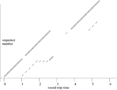
Even with fast retransmission, it is likely that a TCP connection that suffers a lost segment will reach the end of the send window and be forced to stop transmission while awaiting an acknowledgment for the lost segment. However, after the fast retransmission, duplicate acknowledgments are received for each additional packet received by the peer after the lost packet. These duplicate acknowledgments imply that a packet has left the network and is now queued by the receiver. In that case, the packet does not need to be considered as within the network congestion window, possibly allowing additional data to be sent if the receiver's window is large enough. Each duplicate acknowledgment after a fast retransmission thus causes the congestion window to be moved forward artificially by the segment size. If the receiver's window is large enough, it allows the connection to make forward progress during a larger part of the time that the sender awaits an acknowledgment for the retransmitted segment. For this algorithm to have effect, the sender and receiver must have additional buffering beyond the normal bandwidth-delay product; twice that amount is needed for the algorithm to have full effect.
The Internet Control Message Protocol (ICMP) [Postel, 1981c] is the control- and error-message protocol for IPv4. Although it is layered above IPv4 for input and output operations, much like UDP, it is really an integral part of IPv4. Unlike those of UDP, most ICMP messages are received and implemented by the kernel. ICMP messages may also be sent and received via a raw IPv4 socket (see Section 12.7).
ICMP messages fall into three general classes. One class includes various errors that may occur somewhere in the network and that may be reported back to the originator of the packet provoking the error. Such errors include routing failures (network or host unreachable), expiration of the time-to-live field in a packet, or a report by the destination host that the target protocol or port number is not available. Error packets include the IPv4 header plus at least eight additional octets of the packet that encountered the error. The second message class may be considered as router-to-host control messages. Instances of such messages are the source-quench message that reports packet loss caused by excessive output, the routing redirect message that informs a host that a better route is available for a host or network via a different router, and a router advertisements that provides a simple way for a host to discover its router. The final message class includes network management, testing, and measurement packets. These packets include a network-address request and reply, a network-mask request and reply, an echo request and reply, a timestamp request and reply, and a generic information request and reply.
All the actions and replies required by an incoming ICMP message are done by the ICMP module. ICMP packets are received from IPv4 via the normal protocol-input entry point because ICMP has its own IPv4 protocol number. The ICMP input routine handles three major cases. If the packet is an error, such as port unreachable, then the message is processed and delivered to any higher-level protocol that might need to know it, such as the one that initiated the communication. Messages that require a response—for example, an echo—are processed and then sent back to their source with the icmp_reflect() routine. Finally, if there are any sockets listening for ICMP messages, they are given a copy of the message by a call to rip_input() at the end of the icmp_input() routine.
When error indications or source quenches are received, a generic address is constructed in a sockaddr structure. The address and error code are reported to each network protocol's control-input entry, pr_ctlinput(), by the icmp_input() routine. For example, an ICMP port unreachable message causes errors for only those connections with the indicated remote port and protocol.
Routing changes indicated by redirect messages are processed by the rtredirect() routine. It verifies that the router from which the message was received was the next-hop gateway in use for the destination, and it checks that the new gateway is on a directly attached network. If these tests succeed, the kernel routing tables are modified accordingly. If the new route is of equivalent scope to the previous route (e.g., both are for the destination network), the gateway in the route is changed to the new gateway. If the scope of the new route is smaller than that of the original route (either a host redirect is received when a network route was used, or the old route used a wildcard route), a new route is created in the kernel table. Routes that are created or modified by redirects are marked with the flags RTF_DYNAMIC and RTF_MODIFIED, respectively. Once the routing tables are updated, the protocols are notified by pfctlinput(), using a redirect code rather than an error code. TCP and UDP both ignore the redirect message because they do not store a pointer to the route. The next packet sent on the socket will reallocate a route, choosing the new route if that one is now the best route.
Once an incoming ICMP message has been processed by the kernel, it is passed to rip_input() for reception by any ICMP raw sockets. The raw sockets can also be used to send ICMP messages. The low-level network test program ping works by sending ICMP echo requests on a raw socket and listening for corresponding replies.
ICMP is also used by other Internet network protocols to generate error messages. UDP sends only ICMP port unreachable error messages, and TCP uses other means to report such errors. However, many different errors may be detected by IP, especially on systems used as IP routers. The icmp_error() function constructs an error message of a specified type in response to an IP packet. Most error messages include a portion of the original packet that caused the error, as well as the type and code for the error. The source address for the error packet is selected according to the context. If the original packet was sent to a local system address, that address is used as the source. Otherwise, an address is used that is associated with the interface on which the packet was received, as when forwarding is done; the source address of the error message can then be set to the address of the router on the network closest to (or shared with) the originating host. Also, when IP forwards a packet via the same network interface on which that packet was received, it may send a redirect message to the originating host if that host is on the same network. The icmp_error() routine accepts an additional parameter for redirect messages: the address of the new router to be used by the host.
After many successful years of deploying and using IPv4, several issues arose that caused the Internet community to start working on new versions of the Internet protocols. The driving force behind this work was that the original Internet was running out of addresses [Gross & Almquist, 1992]. Several solutions had been proposed and implemented within the IPv4 protocols to handle this problem, including subnetting, and Classless Inter-Domain Routing (CIDR), [Fuller et al., 1993; Mogul & Postel, 1985] but neither of them proved sufficient. Several different proposals were made to completely replace the IPv4 protocols, and it took several years to make a final decision. Work on the new generation of the Internet protocols has been proceeding since the early 1990s, but it was not until 2003 that the protocol was rolled out by any large vendors. To date, the adoption of the new protocols has been limited because of the huge installed base of IPv4 that must be converted.
FreeBSD includes an IPv6 networking domain that contains an implementation of the IPv6 protocols. The domain supports the entire suite of protocols from the network through the transport layers. The protocols are described in a large set of RFCs starting with Deering & Hinden [1998a]. During the development of IPv6, several open-source implementations were written. Each implementation supported a different subset of the full features of IPv6 according to the needs of its authors. The one that eventually had the most complete set was developed by the KAME project [KAME, 2003] and is the implementation that was adopted by FreeBSD.
A complete discussion of IPv6 is beyond the scope of this book. This section discusses the areas of IPv6 that make it different from IPv4 and the changes that had to be made to FreeBSD to accommodate them.
There are several major differences between IPv4 and IPv6 including:
• 128-bit addresses at the network layer
• Emphasis on automatic configuration
• Native support for security protocols
Since a factor driving the move to a new protocol was the need for more addresses, the first change to be made between IPv4 and IPv6 was to enlarge the size of an address. In IPv4, an address, which identifies a unique interface in the network, is 32 bits. This size is theoretically large enough to address over four billion interfaces. There are several reasons why that theoretical maximum is never reached. First is the need to control the size of the routing tables in the core Internet routers. Internet routing is most efficient when many addresses can be communicated by a single address, the address of the router to that network. If each address required its own route, there would be over four billion addresses in every routing table in the Internet, which would not be possible given the current state of network hardware and software. Thus, addresses are aggregated into blocks, and these blocks are assigned to ISPs, who then carve them up into smaller blocks for their customers. The customers then take these blocks and break them down further, through subnetting, and finally assign individual addresses to particular computers. At each level of this hierarchy, some addresses are kept aside for future use, which leads to the second source of IP address waste, overallocation. Because it is expensive and difficult to renumber a large installation of machines, customers request more addresses than they will ever need in an attempt to prevent ever having to renumber their networks. This overallocation has lead to several calls for companies and ISPs to return unused addresses [Nesser, 1996]. For these reasons, the size of an IP address was extended to 128 bits. The number of addresses available in IPv6 has been compared to numbering all the atoms in the universe or giving every person on the earth over a billion IP addresses.
As the Internet has been embraced by people who are not computer scientists and engineers, a major stumbling block has been the difficulty of setting up and maintaining even a single host in the Internet. Companies have teams of professionals who do this work, but for a small company—for example, a dentist's office or a sole proprietorship—the task can be daunting. These difficulties led the designers of IPv6 to include several types of autoconfiguration into the protocol. Ideally, anyone using IPv6 can turn on a computer, connect a network cable to it, and be on the network in a matter of minutes. This goal has not been achieved, but it does explain many of the design decisions in the IPv6 protocols.
Even before the Internet was a commercial success, network researchers and operators understood that the original protocols did not provide any form of security to users of the network. The lack of security was because the environment of the original Internet was one of cooperation, in which the emphasis was on sharing information. IPv6 includes a set of security protocols (IPSec) that are present in IPv4 as well. These protocols are a standard part of IPv6 and are covered in Section 13.10.
The 128-bit addresses in IPv6 necessitated creating new structures to hold them and new interfaces to handle them. While it is reasonably easy to work with the traditional dotted quad notation of IPv4 (i.e., 128.32.1.1), writing out an IPv6 address textually requires a bit more work, which is why the addressing architecture of IPv6 received its own RFC [Deering & Hinden, 1998b]. IPv6 defines several types of addresses:
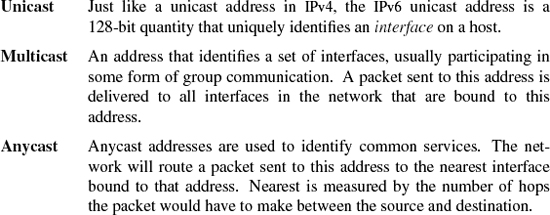
Note that unlike IPv4, IPv6 does not have the concept of a broadcast address that is received by all interfaces on a particular link. The role of broadcast addresses in IPv4 is to provide a way for hosts to discover services even when they do not yet have their own IP address. Broadcast packets are wasteful in that they wake up every host on a link, even if that host does not provide the relevant service. Rather than using broadcast addresses as a way for a host to find a service, IPv6 uses a well-known multicast address for each service being offered. Hosts that are prepared to provide a service register to listen on the well-known multicast address for that service.
When an IPv6 address is written, it is represented as a set of colon-separated hex bytes. The value between each set of colons represents a 16-bit value. For example, the string:
1080:0:0:8:0:0:200C:417A
represents a unicast address in the IPv6 network. When written out as text, a portion of the address that contains zeros may be abbreviated with a double colon:
1080::8:0:0:200C:417A
The first set of two zeros was eliminated in this particular address. When an address is abbreviated, only one set of zeros may be abbreviated. For the run of zeros being eliminated, either all zeros must be removed or none. The following are examples of improper abbreviations of the preceding address:
1080::0:8:0:0:200C:417A
1080::8::200C:417A
The first does not subsume the entire first set of zeros. The second is ambiguous because you cannot tell how to divide the four zeros between the two areas marked with double colons.
Unicast and multicast addresses are differentiated by the bits set at the beginning of the address. All unicast addresses begin with the bits 100, and multicast addresses start with 1111 1111. Examples of the most common addresses are shown in Table 13.5. The unspecified address is used by a host that has not yet been assigned an address when it is in the process of bringing up its network interface. The solicited-node address is used during neighbor discovery, which is covered later in this section.
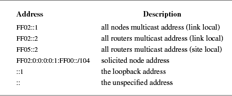
A piece of baggage that was not carried over from IPv4 to IPv6 was the concept of network classes in addresses. IPv6 always uses the CIDR style of marking the boundary between the network prefix (hereafter referred to simply as the prefix) and the interface identifier, which is what identifies an interface on a particular host. The following examples all define the same network, which has a 60-bit prefix:
1234:0000:0000:1230:0000:0000:0000:0000/60
1234::1230:0:0:0:0/60
1234:0:0:1230::/60
When IPv6 was being designed, one goal was to reduce the amount of work necessary for a router to forward a packet. This reduction was addressed as follows:
• Simplification of the packet header. Comparing the IPv6 packet header in Figure 13.12 against the IPv4 header shown in Figure 13.4, we see that there are four fewer fields in the IPv6 header and that only one of them needs to be modified while the packet is in transit: the hop limit. The hop limit is decremented every time the packet is forwarded by a router until the hop limit reaches 0 when the packet is dropped.
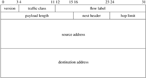
• The packet header is a fixed size. The IPv6 header never carries any options or padding within it. Options processing in IPv4 is an expensive operation that must be carried out whenever an IPv4 packet is sent, forwarded, or received.
• IPv6 strongly discourages the use of fragmentation at the network layer. Avoiding packet fragmentation simplifies packet forwarding as well as processing by hosts (hosts are where the reassembly of fragmented packets take place).
All these simplifications make processing IPv6 packets less compute-intensive than processing those of IPv4. Completely removing features that were inconvenient, such as options or fragmentation, would have decreased the acceptance of IPv6. Instead, the designers came up with a way to add these features, and several others, without polluting the base packet header. Extra features and upper-layer protocols in IPv6 are handled by extension headers. An example packet is shown in Figure 13.13. All extension headers begin with a next-header field as well as an 8-bit length field that shows the length of the extension in units of 8 bytes. All packets are aligned to an 8-byte boundary. The IPv6 header and the extension headers form a chain linked together by the next-header field present in each of them. The next-header field identifies the type of data immediately following the header that is currently being processed and is a direct descendant of the protocol field in IPv4 packets. TCP packets are indicated by the same number in both fields (6). Routers do not look at any of the extension headers when forwarding packets except for the hop-by-hop options header that is meant for use by routers. Each of the extension headers also encodes its length in some way. TCP packets are unaware of being carried over IPv6 and use their original packet-header format, which means they carry neither a next-header field nor a length. The length is computed as it is in IPv4.
Figure 13.13. Extension headers. Key: AH—authentication header (type 51); ESP—encapsulating-security payload (type 50).
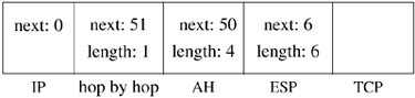
Hosts are required to encode and decode extension headers in a particular order so that it is unnecessary to ever backtrack through a packet. The order in which headers should appear is shown in Figure 13.13. The hop-by-hop header (type 0) must immediately follow the IP header so that routers can find it easily. The authentication header (AH) and encapsulating-security payload (ESP) headers are used by security protocols that are discussed in Section 13.10 and must come before the TCP header and data, since the information in the security headers must be retrieved before they can be used to authenticate and decrypt the TCP header and data.
It has always been the policy of the Internet Engineering Task Force (IETF) to specify protocols and not implementations. For IPv6, this rule was bent so that application developers would have an API to which they could code and speed the migration of applications to IPv6. The designers took the original sockets interface, as it was then implemented in BSD, and specified extensions [Gilligan et al., 1999] that are included in FreeBSD. There were several goals in extending the sockets API:
• The changes should not break existing applications. The kernel should provide backward compatibility for both source and binary.
• Minimize the number of changes needed to get IPv6 applications up and running.
• Ensure interoperability between IPv6 and IPv4 hosts.
• Addresses carried in data structures should be 64-bit aligned to obtain optimum performance on 64-bit architectures.
Adding a new address type was easy because all the routines that handle addresses, such as bind, accept, connect, sendto, and recvfrom, already work with addresses as opaque entities. A new data structure, sockaddr_in6, was defined to hold information about IPv6 endpoints as shown in Figure 13.14. The sockaddr_in6 structure is similar to the sockaddr_in shown in Section 11.4. It contains the length of the structure, the family (which is always AF_INET6), a 16-bit port that identifies the transport-layer endpoint, a flow identifier, network-layer address, and a scope identifier. Many proposals have been put forth for the use of the flow information and scope identifier, but these fields are currently unused. The flow information is intended as a way of requesting special handling for packets within the network. For example a real-time audio stream might have a particular flow label so that it would be given priority over less time-critical traffic. Although the idea is simple to explain, its implementation in a network where no one entity controls all the equipment is problematic. At present there is no way to coordinate what a flow label means when it leaves one network and enters another. Until this conundrum is solved, the flow label will be used only in private network deployments and research labs.
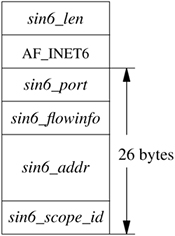
IPv6 defines several scopes in which an address can be used. In IPv4, all addresses were global in scope, meaning that they were valid no matter where they were found on the Internet. The defined scopes in IPv6 are link local, site local, organization local, and global. An address in a lesser scope may not be passed out to a broader scope. For example a link-local address will not be forwarded to another link by a router.
Working with 128-bit addresses by hand is clumsy and error prone. Applications are expected to deal almost exclusively with named entities for IPv6 by using the domain name system (DNS) [Thomson & Huitema, 1995]. The original API for looking up an address from a hostname, gethostbyname(), was specific to the AF_INET domain, so a new API was added to lookup an IPv6 address given a name. When a client wishes to find a server, it uses the gethostbyname2() routine that takes as one of its arguments an address family.
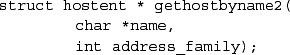
This new API can work with either IPv4 or IPv6 addresses because the second argument specifies the address family and the return value is a pointer to a structure that contains the address type being returned.
A goal of IPv6 is to make adding a computer to the network a simpler process. The mechanisms and protocols that are used to reach this goal are called autoconfiguration. For a host to be automatically configured it has to be able to discover several pieces of information from the network without any prior knowledge. The host must be able to automatically figure out its own address, the address of its next hop router, and the network prefix of the link to which it is attached. To communicate with other hosts on its link and with its next hop router, a host needs the link-level addresses for those other systems. These questions are answered by the neighbor-discovery protocol that is a part of IPv6 and is defined in Narten et al. [1998]. Neighbor discovery either enhances or replaces disparate protocols that were a part of IPv4 and unifies them in a set of ICMPv6 messages [Conta & Deering, 1998]. Because neighbor discovery uses ICMPv6 and thus runs above the IPv6 layer, as long as IPv6 runs on a particular link type, so will neighbor discovery and its auto-configuration services. We will look at two aspects of the neighbor-discovery protocol. The first will be router discovery—how a node finds its next hop router—and the second will be neighbor discovery itself.
A host finds its next hop router in two different ways. IPv6 routers periodically send router-advertisement messages to all nodes multicast address. The format of a router-advertisement message is shown in Figure 13.15. All hosts configured to pick up these multicast packets will see the router advertisement and process it. Although router advertisements are sent often enough to make sure that all hosts on a link know the location of their router and know when it has failed, this mechanism is insufficient for bringing a new host up on the link. When a host first connects to the network, it sends a router-solicitation message to the multicast address of all routers. A router that receives a valid solicitation must immediately send a router advertisement in response. The advertisement will be sent to the multicast address of all nodes unless the router knows that it can successfully send a unicast response to the host that sent the solicitation. A router may send an option with the advertisement that includes the link-layer address of the router. If the link-layer address option is included, the receiving hosts will not need to do neighbor discovery before sending packets to the router.
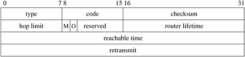
Each host maintains a linked list of its router entries. A single router entry is shown in Figure 13.16. Whenever a router advertisement is received, it is passed to the defrtrlist_update() routine that checks the message to see if it represents a new router and, if so, places a new entry at the head of the default router list. Each router advertisement message contains a lifetime field. This lifetime controls how long an entry may stay in the default router list. Whenever defrtrlist_update() receives a router advertisement for a router that is already present in the default router list, that router's expiration time is extended.
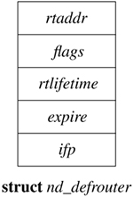
For a host to determine if the next hop to which a packet should be sent is on the same link as itself, it must know the prefix for the link. Historically, the prefix was manually configured on each interface in the system, but now it is handled as part of router discovery.
Prefix information is sent as an option within a router advertisement. The format of the prefix option is shown in Figure 13.17. Each prefix option carries a 128-bit address. The number of valid bits in this address is given by the prefix-length field of the option. For example, the prefix given in the preceding example would be sent in a prefix option with
1234:0000:0000:1230:0000:0000:0000:0000
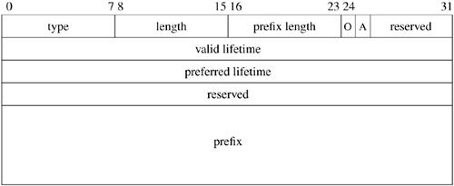
encoded into the prefix field and 60 stored in the prefix-length field. Each prefix is only valid for the period shown by the valid lifetime. Later router advertisements that contain prefix options will have valid lifetimes that move into the future. When a host discovers that it has a prefix whose lifetime has expired, the prefix is removed from the interface with which it is associated, and the expired prefix no longer determines whether a destination address is on the local link.
When a host has a packet for another host on its link, including its next-hop router, it must find the link-layer address of the host to which it wishes to send the packet. In IPv4, this process was handled by the address-resolution protocol (ARP); see Section 12.8. A problem with ARP is that it is Ethernet specific and has encoded in it assumptions about link-layer addresses that makes it difficult to adapt to other link types.
A host learns the link-layer addresses of its neighbors using a pair of messages: the neighbor solicitation and the neighbor advertisement. When the kernel wants to send an IPv6 packet to another host, the packet eventually passes through the ip6_output() routine, which does various checks on the packet to make sure that it is suitable for transmission. All properly formed packets are then passed down to the neighbor-discovery module via the nd6_output() routine that handles mapping an IPv6 address to a link-layer address. Once the packet has a correct link-layer destination address, it is passed to a network-interface driver via the driver's if_output() routine. The relationships between the various protocol modules are shown in Figure 13.18 (on page 568). The neighbor-discovery module does not have an nd_input() routine because it receives messages via the ICMPv6 module. This inversion of the protocol layering allows the neighbor-discovery protocol to be independent of the link layer. In IPv4, the ARP module is hooked into the network interface so that it can send and receive messages. The connection between ARP and the underlying link-layer interfaces means that the ARP code must understand every link type that the system supports.
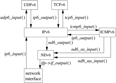
Link-layer addresses are stored in the routing table, and that is where nd6_output() attempts to lookup the link-layer address for the packets that are passed to it. When the host does not yet know the link-layer address for the destination, the outgoing packet must be held until neighbor discovery completes. Each rtentry structure contains a pointer to link-layer information. When a route entry stores information for IPv6, it points to an llinfo_nd6 structure, as shown in Figure 13.19. Before a neighbor solicitation is sent, the packet that the kernel is attempting to transmit is saved by making the In_hold field of the llinfo_nd6 structure point to it. It is only possible to store one packet at a time, so if the system attempts to transmit another packet to the same link-layer destination before a neighbor advertisement is received, the first packet will be lost and upper layers will have to retransmit it. The nd6_output() routine does not wait for the neighbor advertisement but returns. When a response is received as a neighbor advertisement, it is processed by the IPv6 and ICMPv6 modules and is finally passed into the neighbor-discovery module by a call to the nd6_na_input() routine, as shown in Figure 13.18. The nd6_na_input() routine records the link-layer address and checks to see if a packet was being held for transmission to that destination. If there is a packet awaiting transmission, the nd6_output() routine is invoked with the saved packet. A link-layer address for the saved packet's destination is now in the system, so nd6_output() will copy the link-layer address into the mbuf chain and invoke the network interface's if_output() routine to transmit the packet.
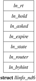
Once per second the nd6_timer() routine walks the neighbor-discovery link-layer address list as well as the default-router and interface lists and removes the entries that have passed their expiration time. Removing stale entries prevents the system from trying to send data to a host that has failed or become unreachable.
We mentioned in Section 13.9 that a suite of security protocols were developed as part of IPv6. These protocols were written to be independent of a particular version of IP, so they have been integrated into IPv4 and IPv6. At the network layer, security mechanisms have been added to provide authentication so that one host can know with whom it is communicating. Encryption has been added so that data can be hidden from untrusted entities as it crosses the Internet. The protocols that collectively provide security within the network layer are referred to as IPSec.
Placing the security protocols at the network layer within the protocol stack was not an arbitrary decision. It is possible to place security at just about any layer within a communication system. For example, the secure sockets layer (SSL) supports communication security at the application layer and allows a client and a server to communicate securely over an arbitrary network. At the opposite end of the spectrum are the various protocols that support security over wireless networks that work at the data-link layer. The decision to put security at the network layer was made for several reasons:
• The IP protocols act as a uniform platform into which to place the security protocols. Differences in underlying hardware, such as different types of network media, did not have to be taken into account when designing and implementing IPSec because if a piece of hardware could send and receive IP datagrams, then it could also support IPSec.
• Users need not do any work to use the security protocols. Because IPSec is implemented at the network, instead of the application layer, users that run network programs are automatically working securely as long as their systems administrators have properly configured the system.
• Key management can be handled in an automatic way by system daemons. The hardest problem in deploying network security protocols is giving out and canceling the keys used to encrypt the data. Since IPSec is handled in the kernel, and is not usually dealt with by users, it is possible to write daemons to handle the management of keys.
Security within the context of IPSec means several things:
• The ability to trust that a host is who it claims to be (authentication)
• Protection against the replay of old data
• Confidentiality of data (encryption)
Providing a security architecture for the Internet protocols is a complex problem. The relevant protocols are covered in several RFCs, and an overview is given in Kent & Atkinson [1998a].
FreeBSD contains two implementations of IPSec. One is derived from the KAME code base, and the other, known as Fast IPSec, is a reworking of the KAME code base so that it can work with the OpenBSD cryptographic subsystem [Leffler, 2003a]. The largest difference between the two code bases is that the Fast IPSec code does not have any cryptographic algorithms built into it and depends wholly on the cryptographic subsystem to handle the work of encrypting, decrypting, and otherwise manipulating data. Although the KAME code was the first implementation available of the IPSec protocols, and is still the most widely used, we discuss the Fast IPSec code because it allows us to explain the hardware cryptography subsystem that has been added to FreeBSD.
The protocols that make up IPSec provide a security framework for use by hosts and routers on the Internet. Security services, such as authentication and encryption, are available between two hosts, a host and a router, or two routers. When any two entities on the network (hosts or routers) are using IPSec for secure communication, they are said to have a security association (SA) between them. Each SA is unidirectional, which means that traffic is only secured between two points in the direction in which the SA has been set up. For a completely secure link two SAs are required, one in each direction.
SAs are uniquely identified by their destination address, the security protocol being used, and a security-parameter index (SPI), which is a 32-bit value that distinguishes among multiple SAs terminating at the same host or router. The SPI is the key used to lookup relevant information in the security-association database that is maintained by each system running IPSec.
An SA can be used in two modes. In transport mode, a portion of the IP header is protected as well as the IPSec header and the data. The IP header is only partially protected because it must be inspected by intermediate routers along the path between two hosts, and it is not possible, or desirable, to require every possible router to run the IPSec protocols. One reason to run security protocols end to end is so intermediate routers do not have to be trusted with the data they are handling. Another reason is that security protocols are often computationally expensive and intermediate routers often do not have the computational power to decrypt and reencrypt every packet before it is forwarded.
Since only a part of the IP header is protected in transport mode, this type of SA only provides protection to upper-layer protocols, those that are completely encapsulated within the data section of the packet, such as UDP and TCP. Figure 13.20 shows a transport-mode SA from Host A to Host D as well as the packet that would result. Host A sets up a normal IP packet with a destination of host D. It then adds the IPSec header and data. Finally, it applies whatever security protocol has been selected by the user and sends the packet, which travels through Router B to Router C and finally to Host D. Host D decrypts the packet by looking up the security protocol and keys in its security-association database.
Figure 13.20. Security association in transport mode. Key: AH—authentication header; ESP—encapsulating-security payload; SPI—security-parameter index.

The other mode is tunnel mode, shown in Figure 13.21 (on page 572), where the entire packet is placed within an IP-over-IP tunnel [Simpson, 1995]. In tunneling, the entire packet, including all the headers and data, are placed as data within another packet and sent between two locations. Host A wants to send a packet to Host D. When the packet reaches Router B, it is placed in a secure tunnel between Router B and Router C. The entire original packet is placed inside a new packet and secured. The outer IP header identifies only the endpoints of the tunnel (Router B and Router C) and does not give away any of the original packet's header information. When the packet reaches the end of the tunnel at Router C, it is decrypted and then sent on to its original destination of Host D. In this example, neither Host A nor Host D knows that the data have been encrypted nor do they have to be running the IPSec protocols to participate in this secure communication.
Figure 13.21. Security association in tunnel mode. Key: AH—authentication header; ESP—encapsulating-security payload; SPI—security-parameter index.
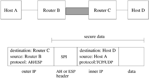
Tunnel mode is only used for host-to-router or router-to-router communications and is most often seen in the implementation of virtual private networks that connect two private networks or connect users to a corporate LAN over the public Internet.
There are two security protocols specified for use with IPSec: the authentication header (AH) and the encapsulating-security payload (ESP), each of which provides different security services [Kent & Atkinson, 1998b; Kent & Atkinson, 1998c]. Both protocols are used with IPv4 and IPv6 without changes to their headers. This dual usage is possible because the packet headers are really IPv6 extension headers that properly encode information about the other protocols following them in the packet.
The AH protocol provides a packet-based authentication service as well as protection against an attacker attempting to replay old data. To understand how AH provides security, it is easiest to look at its packet header, shown in Figure 13.22. The next-header field identifies the type of packet that follows the current header. The next-header field uses the same value as the one that appears in the protocol field of an IPv4 packet: 6 for TCP, 17 for UDP, and 1 for ICMP. The payload length specifies the number of 32-bit words that are contained in the authentication header minus 2. The fudge factor of removing 2 from this number comes from the specification for IPv6 extension headers. The SPI was just explained and is simply a 32-bit number that is used by each endpoint to lookup relevant information about the security association.
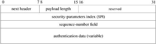
Authentication is provided by computing an integrity-check value (ICV) over the packet. If an AH is used in transport mode, then only parts of the IP header are protected because some of the fields are modified by intermediate routers in transit and the changes are not predictable at the sender. In tunnel mode, the whole header is protected because it is encapsulated in another packet, and the ICV is computed over the original packet. The ICV is computed using the algorithm specified by the SPI with the result stored in the authentication-data field of the authentication header. The receiver uses the same algorithm, requested by the SPI to compute the ICV on the packet it received, and compares this value with the one found in the packet's authentication-data field. If the values are the same, then the packet is accepted; otherwise, it is discarded.
One possible attack on a communication channel is to send new or false data as if it were coming from the authentic source, which is called a replay attack. To guard against a replay attack, the AH protocol uses a sequence-number field to uniquely identify each packet that is transmitted across an SA. This sequencenumber field is distinct from the field of the same name in TCP. When an SA is established, both the sender and receiver set the sequence number to zero. The sender increments the sequence number before transmitting a packet. The receiver implements a fixed-size sliding window, with its left edge being the lowest sequence number that it has seen and validated and the right edge being the highest. When a new packet is received, its sequence number is checked against the window with three possible results:
• The packet's sequence number is less than the one on the left edge of the window, and the packet is discarded.
• The packet's sequence number is within the window. The packet is checked to see if it is a duplicate, and if so is discarded. If the packet is not a duplicate, it is inserted into the window.
• The packet's sequence number is to the right of the current window. The ICV is verified, and, if correct, the window is moved to the right to encompass the new sequence number value.
When the sequence number rolls over, after over 4 billion packets, the security association must be torn down and restarted. This restart is only a slight inconvenience because at gigabit Ethernet rates of 83,000 packets per second it takes over 14 hours for the security sequence number to roll over.
All senders assume that a receiver is using the antireplay service and always increment the sequence number, but it is not required for the receiver to implement the antireplay service, and it may be turned off at the discretion of the operator of the receiving system.
In addition to the services provided by the AH, the ESP also provides confidentiality using encryption. As with the AH it is easiest to understand the ESP if we examine its packet header, shown in Figure 13.23. The ESP header contains all the same fields as were found in the AH header, but it adds three more. The encrypted data sent using an ESP is stored in the payload-data field of the packet. The padding field that follows the payload data may be used for three purposes:
• The encryption algorithm might require that the data to be encrypted be some multiple number of bytes. The padding data is added to the data to be encrypted so that the chunk of data is of the correct size.
• Padding might be required to properly align some part of the packet. For example, the pad-length and next-header fields must be right-aligned in the packet, and the authentication-data field must be aligned on a 4-byte boundary.
• The padding may also be used to obscure the original size of the payload in an attempt to prevent an attacker from gaining information by watching the traffic flow.
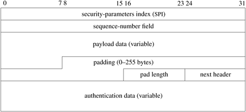
User-level applications cannot use IPSec in the same way that they use transport protocols like UDP and TCP. For example, an application cannot open a secure socket to another endpoint using IPSec. Instead, all SAs are kept in the kernel and managed using a new domain and protocol family called PF_KEY_V2 [McDonald et al., 1998].
The automated distribution of keys for use in IPSec is handled by the Internet key exchange (IKE) protocol [Harkins & Carrel, 1998]. User-level daemons that implement the IKE protocol, such as Racoon, interact with the kernel using PF_KEY_V2 sockets [Sakane, 2001]. As these daemons are not implemented in the kernel, they are beyond the scope of this book.
User-level applications interact with the security database by opening a socket of type PF_KEY. There is no corresponding AF_KEY address family. Key sockets are based on the routing-socket implementation and function much like a routing socket. Whereas the routing-socket API manipulates the kernel routing table, the key-socket API manages security associations and policies. Key sockets support a connectionless-datagram facility between user applications and the kernel. User-level applications send commands in packets to the kernel's security database. Applications can also receive messages about changes to the security database, such as the expiration of security associations, by reading from a key socket.
The messages that can be sent using a key socket are shown in Table 13.6. Two groups of messages are defined for key sockets: a base set of messages that all start with SADB and a set of extension messages that starts with SADB_X. The type of the message is the second part of the name. In FreeBSD, the extension messages manipulate a security-policy database (SPDB) that is separate from the security-association database (SADB).
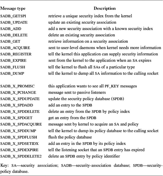
Key-socket messages are made up of a base header, shown in Figure 13.24, and a set of extension headers. The base header contains information that is common to all messages. The version ensures that the application will work with the version of the key-socket module in the kernel. The command being sent is encoded in the message-type field. Errors are sent to the calling socket using the same set of headers that are used to send down commands. Applications cannot depend on all errors being returned by a send or write system call made on the socket, and they must check the error number of any returned message on the socket for proper error handling. The errno field is set to an appropriate error number before the message is sent to the listening socket. The type of security association that the application wants to manipulate is placed in the SA-type field of the packet. The length of the entire message, including the base header, all extension headers, and any padding that has been inserted is stored in the length field. Each message is uniquely identified by its sequence and PID fields that match responses to requests. When the kernel sends a message to a listening process the PID is set to 0.
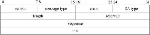
The security-association database and security-policy database cannot be changed using only the base header. To make changes, the application adds one or more extension headers to its message. Each extension header begins with a length and a type so that the entire message can be easily traversed by the kernel or an application. An association extension is shown in Figure 13.25. The association extension makes changes to a single security association, such as specifying the authentication or encryption algorithm to be used.
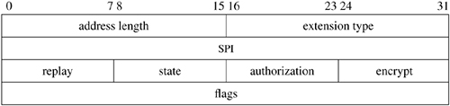
Whenever an association extension is used, an address extension must be present as well, since each security association is identified by the network addresses of the communicating endpoints. An address extension, shown in Figure 13.26, stores information on the IPv4 or IPv6 addresses using sockaddr structures.
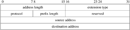
One problem with the current PF_KEY implementation is that it is a datagram protocol, and the message size is limited to 64 kilobytes. A 64-kilobyte limit is not important to users with small databases, but when a system using IPSec is deployed in a large enterprise, with hundreds and possibly thousands of simultaneous security associations, the SADB will grow large, and this limitation makes it more difficult to write user-level daemons to manage the kernel's security databases.
The purpose of key sockets is to manage the security-association database stored in the kernel. Like many other data structures in FreeBSD, security-association structures are really objects implemented in C. Each security-association structure contains all the data related to a specific security association as well as the set of functions necessary to operate on packets associated with it.
The security-association database is stored as a doubly linked list of security-association structures. A security-association structure is shown in Figure 13.27 (on page 578). Each security association can be shared by more than one entity in the system, which is why they contain a reference count. Security associations can be in four states: LARVAL, MATURE, DYING, and DEAD. When an SA is first being created, it is put into the LARVAL state, which indicates that it is not currently usable but is still being set up. Once an SA is usable, it moves to the MATURE state. An SA remains in the MATURE state until some event, such as the SA exceeding its lifetime, moves it to the DYING state. SAs in the DYING state can be revived if an application makes a request to use an SA with the same parameters before it is marked as DEAD.
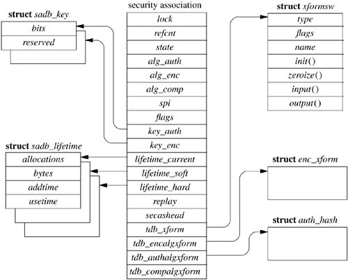
The security-association structure contains all the information on a particular SA including the algorithms used, the SPI, and the key data. All this information is used in processing packets for a particular association. The lifetime fields limit the usage of a particular SA. Although an SA is not required to have a lifetime, and so might not expire, recommended practice is to set a lifetime. Lifetimes can be given a time limit using the addtime and usetime fields. Lifetimes can be given a data-processing limit using the bytes field. The three lifetime structures pointed to by the security association encode the current usage for the association as well as its hard and soft limits. When reached, the soft-lifetime value puts the SA into the DYING state to show that its useful life is about to end. When reached, the hard-lifetime value indicates that the SA is no longer usable at all. Once an SA passes the hard-lifetime limit, it is set to the DEAD state and can be reclaimed. The current-lifetime structure contains the present usage values for the SA—for example, how many bytes have been processed since the SA was created.
Each security-association structure has several tables of functions that point to routines that do the work on packets handled by that association. The tdb_xform table contains pointers to functions that implement the initialization and input and output functions for a particular security protocol such as ESP or AH. The other three tables are specific to a protocol and contain pointers to the appropriate cryptographic functions for handling the protocol being used by the SA. The reason for having this plethora of tables is that the cryptographic subsystem ported from OpenBSD used these tables to encapsulate the functions that do the real work of cryptography. To simplify the maintenance of the code, this set of interfaces and tables was retained during the port. A useful side effect of having these tables is that it makes adding new protocols or cryptographic routines simple. We describe how these tables are used later in this section.
Key sockets are implemented in the same way as other socket types. There is a domain structure, keydomain; a protocol-switch structure, keysw; a set of user-request routines, key_usrreqs; and an output-routine, key_output(). Only those routines necessary for a connectionless-datagram type of protocol are implemented in the key_usrreqs structure. Any attempt to use a key socket in a connection-oriented way—for instance, by calling connect on a key socket—will result in the kernel returning EINVAL to the caller.
When an application writes to a key socket, the message is eventually transferred down into the kernel and is handled by the key_output() routine. After some rudimentary error checking the message is passed to key_parse(), which does more error checks, and then is finally shuttled off through a function-pointer switch called key_types. The functions pointed to by key_types are those that do the manipulation of the security-association and security-policy databases.
If the kernel needs to send a message to listening applications because of changes in the security databases, it uses the key_sendup_mbuf() routine to copy the message to one or more listening sockets. Each socket receives its own copy of the message.
The IPSec protocols affect all areas of packet handling in the IPv4 and IPv6 protocol stacks. In some places, IPSec uses the existing networking framework, and in others, direct callouts are made to do some part of the security processing. We will look at three of the possible paths through the IPv4 stack: inbound, outbound, and forwarding.
One twist that IPSec adds to normal packet processing is the need to process some packets more than once. An example is the arrival of an encrypted packet bound for the current system. The packet will be processed once in its encrypted form and then a second time, by the same routines, after it has been decrypted. This multipass processing is unlike regular TCP or UDP processing where the IP header is stripped from the packet and the result is handed to the TCP or UDP modules for processing and eventual delivery to a socket. This continuation style of processing packets is one reason that the IPSec software makes extensive use of packet tags. Another reason to use packet tags is that parts of IPSec, namely the cryptographic algorithms, can be supported by special-purpose hardware accelerators. A hardware accelerator may do all or part of the security processing, such as checking a packet's authentication information or decrypting the packet payload, and then pass the resulting packet into the protocol stack for final delivery to a waiting socket. The hardware needs some way to tell the protocol stack that it has completed the necessary work. It is neither possible, nor desirable, to store this information in the headers or data of the packet. Adding such information to a packet's header is an obvious security hole because a malicious sender could simply set the appropriate field and bypass the security processing. It would have been possible to extend the mbuf structure to handle this functionality, but packet tags are a more flexible way of adding meta-data to packets without modifying a key data-structure in the network stack. The tags used by IPSec are described in Table 13.7.
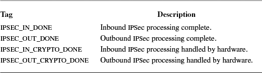
As we saw in Section 13.3, when an IPv4 packet is received by the kernel it is initially processed by ip_input(). The ip_input() routine does two checks on packets that are related to IPSec. The first is to see if the packet is really part of a tunnel. If a packet is being tunneled, then if it has been processed by the IPSec software already, it can bypass any filtering by filter hooks or the kernel fire-walling code. The second check is done when a packet is to be forwarded. Routers can implement security policies on packets that are forwarded. Before a packet is passed to ip_forward(), it is checked by calling the ipsec_getpolicy() function to see if there is a policy that is associated with the packet itself. The ipsec_getpolicybyaddr() function is called to check if there is a policy associated with the address of the packet. If either function returns a pointer to a policy routine, the packet is passed to that policy routine to be checked. If the packet is rejected, it is silently dropped and no error is returned to the sender.
When ip_input() has determined that the packet is valid and is destined for the local machine, the protocol-stack framework takes over. The packet is passed to the appropriate input routine using the pr_input field of the inetsw structure. Although packets using different protocols have different entry points, they eventually wind up being passed to a single routine, ipsec_common_input(), for processing. The ipsec_common_input() routine attempts to find the appropriate security-association structure for the packet based on its destination address, the security protocol it is using, and the SPI. If an appropriate association is found, then control is passed to the input routine contained in the SA's xform-switch structure. The security protocol's input routine extracts all the relevant data from the packet—for example, the key being used—and creates a cryptography-operation descriptor. This descriptor is then passed into the cryptographic routines. When the cryptographic routines have completed their work, they call a protocol-specific callback routine, which modifies the mbufs associated with the packet so that it may now be passed, unencrypted, back into the protocol stack via the ip_input() routine.
Applications do not know that they are using IPSec to communicate with other hosts in the Internet. For outbound packets, the use of IPSec is really controlled from within the ip_output() routine. When an outbound packet reaches the ip_output() routine, a check is made to see if there is a security policy that applies to the packet, either because of its destination address or because of the socket that sent it. If a security policy is found, then the packet is passed into the IPSec code via the ipsec4_process_packet() routine. If a security association has not been set up for this particular destination, one is created in the security-association database for it. The ipsec4_process_packet() uses the output() routine from the xform switch in the security association to pass off the packet to the security-protocol's output routine. The security-protocol's output routine uses the appropriate cryptographic routine to modify the packet for transmission. Once the packet has been modified appropriately, it is passed again into ip_output() but with the tag PACKET_TAG_IPSEC_OUT_DONE attached to it. This tag marks the packet as having completed IPSec processing, showing that it can now be transmitted like any other packet.
Underlying all the security protocols provided by IPSec is a set of APIs and libraries that support cryptography. The cryptographic subsystem in FreeBSD supports both symmetric and asymmetric cryptography. Symmetric cryptography, used by IPSec, uses the same key to encrypt data as it does to decrypt it. Asymmetric cryptography, which implements public key encryption, uses one key to encrypt data and another key to decrypt it. This section describes how symmetric cryptography is implemented as it relates to a specific client, IPSec.
The cryptographic subsystem was ported from OpenBSD and optimized for a fully preemptive, SMP kernel [Leffler, 2003b]. In FreeBSD, cryptographic algorithms exist either in software or special-purpose hardware. The software module that provides support for cryptography is implemented in exactly the same way as the drivers for cryptographic hardware. This similarity means that, from the cryptography subsystem's point of view, the software and hardware drivers are the same. Upper-level users of the cryptography subsystem, such as IPSec, are all presented with the same API whether the cryptographic operations they request are being done in hardware or software.
The cryptography subsystem is implemented by two sets of APIs and two kernel threads. One set of APIs is used by software that wishes to use cryptography; the other set is used by device-driver writers to provide an interface to their hardware. The model of computation supported by the cryptographic subsystem is one of job submission and callbacks where users submit work to be done to a queue and supply a pointer to a function that will be called when the job is completed.
Before a cryptography user can submit a work to the cryptography subsystem, they must first create a session. A session is a way of encapsulating information about the type of work that the user is requesting. It is also a way of controlling the amount of resources consumed on the device, since some devices have a limitation to the amount of concurrent work they can support. A user creates a session using the crypto_newsession() routine that returns either a valid session identifier or an error.
Once the user has a proper session identifier, they then request a cryptographic descriptor, shown in Figure 13.28. The user fills in the fields of the cryptographic descriptor, including supplying an appropriate callback in the crp_callback element. When the descriptor is ready, it is handed to the cryptographic subsystem via the crypto_dispatch() routine that puts it on a queue to be processed. When the work is complete, the callback is invoked. All callbacks are of the form:
int (*crp_callback)(
struct cryptop *arg);
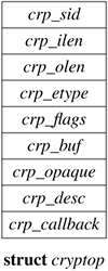
If an error has occurred, the error code is contained in the crp_etype field of the cryptographic descriptor that is passed to the callback.
A set of device drivers provides the low-level interface to specialized cryptographic hardware. Each driver provides three function pointers to the cryptographic subsystem when it registers itself. Driver registration is done via a call to the crypto_register() routine.
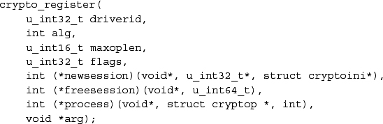
The newsession() routine is called by the cryptographic subsystem whenever the crypto_newsession () routine is called by a user. The freesession() routine is called whenever the crypto_freesession() routine is called by a user, and the process() routine is called by the crypto_proc() kernel thread to pass operations into the device.
The lower half of the cryptographic subsystem uses two software interrupt threads and two queues to control the underlying hardware. Whenever there are requests on the crp_q queue, the crypto_proc() thread dequeues them and sends them to the underlying device, using the crypto_invoke() routine. Once invoked, the underlying hardware has the responsibility to handle the request. The only requirement is that when the hardware has completed its work, the device driver associated with the hardware must invoke crypto_done() that either enqueues the callback on the crp_ret_q queue or more rarely directly calls the user's callback. The crp_ret_q queue is provided because the crypto_done() routine often will be called from an interrupt context, and running the user's callback with interrupts locked out will degrade the interactive performance of the system. When running in an interrupt context, the callback will be queued and then handled later by the crypto_ret_proc software interrupt thread. This use of queues and software interrupt threads effectively decouples the kernel from any possible performance issues introduced by a variety of cryptographic hardware.
Unfortunately, there are several problems with the system just described:
• Using multiple threads requires two context switches per cryptographic operation. The context switches are nontrivial and severely degrade throughput.
• Some callback routines do little work, and so moving all callbacks out of the device driver's interrupt service routine adds another context switch that is expensive and unnecessary.
• The dispatch queue batches operations, but many users of the cryptographic subsystem, including IPSec, do not batch operations, so this shunting of work into the dispatch queue is unnecessary overhead.
To address these performance problems several changes were made to the cryptographic subsystem. Cryptographic drivers are now supplied a hint whether there is more work to follow when work is submitted to them. The drivers can decided whether to batch work based on this hint and, where requests are not batched, completely bypass the crp_q queue. Cryptographic requests whose callback routines are short mark their requests so that the underlying device executes them directly instead of queueing them on the crypto_ret_q queue. The optimization of bypassing the crypto_req_q queue is especially useful to users of the /dev/crypto device, whose callback routine awakens only the thread that wrote to it. All these optimizations are described more fully in Leffler [2003b].
13.1 Is TCP a transport-, network-, or link-layer protocol?
13.2 How does IPv4 identify the next-higher-level protocol that should process an incoming message? How might this dispatching differ in other networking architectures?
13.3 How many hosts can exist in an IPv4 subnet with a mask of 255.255.255.0?
13.4 What is a broadcast message? How are broadcast messages identified in IPv4? How are IPv6 broadcast messages identified?
13.5 Why are TCP and UDP protocol control blocks kept on separate lists?
13.6 Why does the output routine, rather than the socket-layer send routine (sosend()), check the destination address of an outgoing packet to see whether the destination address is a broadcast address?
13.7 Why does FreeBSD not forward broadcast messages?
13.8 Why does the TCP header include a header-length field even though it is always encapsulated in an IP packet that contains the length of the TCP message?
13.9 What is the flow-control mechanism used by TCP to limit the rate at which data are transmitted?
13.10 How does TCP recognize messages from a host that are directed to a connection that existed previously but that has since been shut down (such as after a machine is rebooted)?
13.11 When is the size of the TCP receive window for a connection not equal to the amount of space available in the associated socket's receive buffer? Why are these values not equal at that time?
13.12 What are keepalive messages? For what does TCP use them? Why are keepalive messages implemented in the kernel rather than, say, in each application that wants this facility?
13.13 Why is calculating a smoothed round-trip time important, rather than, for example, just averaging calculated round-trip times?
13.14 Why does TCP delay acknowledgments for received data? What is the maximum time that TCP will delay an acknowledgment?
13.15 Explain what the silly-window syndrome is. Give an example in which its avoidance is important to good protocol performance. Explain how the FreeBSD TCP avoids this problem.
13.16 What is meant by small-packet avoidance? Why is small-packet avoidance bad for clients (e.g., the X Window System) that exhibit one-way data flow and that require low latency for good interactive performance?
13.17 Describe three ways in which IPv6 differs from IPv4.
13.18 In IPv6, what protocol replaces ARP for translating IP addresses to hardware addresses?
13.19 What does the networking code use the network mask, or prefix, of a link to determine?
13.20 Why are there separate protocols for authentication and encryption in IPSec?
13.21 Why is the cryptographic subsystem implemented using two queues and two kernel threads?
13.22 What limitation of ARP does neighbor discovery overcome? How does it overcome this limitation?
13.23 How is the protection offered to packets by IPSec different in tunnel mode and transport mode?
*13.24 Why is the initial sequence number for a TCP connection selected at random, rather than being, say, always set to zero?
*13.25 In the TCP protocol, why do the SYN and FIN flags occupy space in the sequence-number space?
*13.26 Describe a typical TCP packet exchange during connection setup. Assume that an active client initiated the connection to a passive server. How would this scenario change if the server tried simultaneously to initiate a connection to the client?
*13.27 Sketch the TCP state transitions that would take place if a server process accepted a connection and then immediately closed that connection before receiving any data. How would this scenario be altered if FreeBSD TCP supported a mechanism where a server could refuse a connection request before the system completed the connection?
*13.28 Why does UDP match the completely specified destination addresses of incoming messages to sockets with incomplete local and remote destination addresses?
*13.29 Why might a sender set the Don't Fragment flag in the header of an IP packet?
*13.30 The maximum segment lifetime (MSL) is the maximum time that a message may exist in a network—that is, the maximum time that a message may be in transit on some hardware medium or queued in a gateway. What does TCP do to ensure that TCP messages have a limited MSL? What does IP do to enforce a limited MSL? See Fletcher & Watson [1978] for another approach to this issue.
*13.31 Why does TCP use the timestamp option in addition to the sequence number in detecting old duplicate packets? Under what circumstances is this detection most desirable?
**13.32 Describe a protocol for calculating a bound on the maximum segment lifetime of messages in an Internet environment. How might TCP use a bound on the MSL (see Exercise 13.30) for a message to minimize the overhead associated with shutting down a TCP connection?
**13.33 Describe path MTU discovery. Can FreeBSD take advantage of the fact that the MTU of a path has suddenly increased? Why or why not?
**13.34 What are the tradeoffs between frequent and infrequent transmission of router advertisements in IPv6?
**13.35 Since IPSec may call routines in the network stack recursively, what requirement does this place on the code?
**13.36 Describe three paths that a packet can take through the networking code. How and where is each path chosen?
References
Bellovin, 1996.
S. Bellovin, "Defending Against Sequence Number Attacks," RFC 1948, available from http://www.faqs.org/rfcs/rfcl948.html, May 1996.
Cain et al., 2002.
B. Cain, S. Deering, I. Kouvelas, B. Fenner, & A. Thyagarajan, "Internet Group Management Protocol, Version 3," RFC 3376, available from http://www.faqs.org/rfcs/rfc3376.html, October 2002.
Cerf & Kahn, 1974.
V. Cerf & R. Kahn, "A Protocol for Packet Network Intercommunication," IEEE Transactions on Communications, , no. 5, pp. 637-648, May 1974.
Clark, 1982.
D. D. Clark, "Window and Acknowledgment Strategy in TCP," RFC 813, available from http://www.faqs.org/rfcs/rfc813.html, July 1982.
Conta & Deering, 1998.
A. Conta & S. Deering, "Internet Control Message Protocol (ICMPv6) for the Internet Protocol Version 6 (IPv6) Specification," RFC 2463, available from http://www.faqs.org/rfcs/rfc2463.html, December 1998.
DARPA, 1983. DARPA,
"A History of the ARPANET: The First Decade," Technical Report, Bolt, Beranek, and Newman, Cambridge, MA, April 1983.
Deering, 1989.
S. Deering, "Host Extensions for IP Multicasting," RFC 1112, available from http://www.faqs.org/rfcs/rfc1112.html, August 1989.
Deering & Hinden, 1998a. S. Deering & R. Hinden, "Internet Protocol, Version 6 (IPv6)," RFC 2460, available from http://www.faqs.org/rfcs/rfc2460.html, December 1998.
Deering & Hinden, 1998b.
S. Deering & R. Hinden, "IP Version 6 Addressing Architecture," RFC 2373, available from http://www.faqs.org/rfcs/rfc2373.html, July 1998.
Fletcher & Watson, 1978.
J. Fletcher & R. Watson, "Mechanisms for a Reliable Timer-Based Protocol," in Computer Networks 2, pp. 271-290, North-Holland, Amsterdam, The Netherlands, 1978.
Fuller et al., 1993.
V Fuller, T. Li, J. Yu, & K. Varadhan, "Classless Inter-Domain Routing (CIDR): An Address Assignment and Aggregation Strategy," RFC 1519, available from http://www.faqs.org/rfcs/rfc1519.html, September 1993.
Gilligan et al., 1999.
G. Gilligan, S. Thomson, J. Bound, & W. Stevens, "Basic Socket Interface Extensions for IPv6," RFC 2553, available from http://www.faqs.org/rfcs/rfc2553.html, March 1999.
Gross & Almquist, 1992.
P. Gross & P. Almquist, "IESG Deliberations on Routing and Addressing," RFC 1380, available from http://www.faqs.org/rfcs/rfc1380.html, November 1992.
Harkins & Carrel, 1998.
D. Harkins & D. Carrel, "The Internet Key Exchange (IKE)," RFC 2409, available from http://www.faqs.org/rfcs/rfc2409.html, November 1998.
ISO, 1984.
, "Open Systems Interconnection: Basic Reference Model," ISO 7498, International Organization for Standardization, available from the American National Standards Institute, 1430 Broadway, New York, NY 10018, 1984.
Jacobson, 1988.
V Jacobson, "Congestion Avoidance and Control," Proceedings of the ACM SIGCOMM Conference, pp. 314-329, August 1988.
Jacobson et al., 1992.
V Jacobson, R. Braden, & D. Borman, "TCP Extensions for High Performance," RFC 1323, available from http://www.faqs.org/rfcs/rfc1323.htm1, May 1992.
KAME, 2003. KAME,
"Overview of KAME Project," Web site, http://www.kame.net/project-overview.html#overview, December 2003.
Kent & Atkinson, 1998a.
S. Kent & R. Atkinson, "Security Architecture for the Internet Protocol," RFC 2401, available from http://www.faqs.org/rfcs/rfc2401.htm1, November 1998.
Kent & Atkinson, 1998b.
S. Kent & R. Atkinson, "IP Authentication Header," RFC 2402, available from http://www.faqs.org/rfcs/rfc2402.htm1, November 1998.
Kent & Atkinson, 1998c. S. Kent & R. Atkinson, "IP Encapsulating Security Payload (ESP)," RFC 2406, available from http://www.faqs.org/rfcs/rfc2406.html, November 1998.
Leffler, 2003a.
S. Leffler, "Fast IPSec: A High-Performance IPSec Implementation," Proceedings of BSDCon 2003, September 2003.
Leffler, 2003b.
S. Leffler, "Cryptographic Device Support for FreeBSD," Proceedings of BSDCon 2003, September 2003.
McDonald et al., 1998.
D. McDonald, C. Metz, & B. Phan, "PF_KEY Key Management API, Version 2," RFC 2367, available from http://www.faqs.org/rfcs/rfc2367.html, July 1998.
McQuillan & Walden, 1977.
J. M. McQuillan & D. C. Walden, "The ARPA Network Design Decisions," Computer Networks, , no. 5, pp. 243–289, 1977.
Mogul, 1984.
J. Mogul, "Broadcasting Internet Datagrams," RFC 919, available from http://www.faqs.org/rfcs/rfc9l9.html, October 1984.
Mogul & Deering, 1990.
J. Mogul & S. Deering, "Path MTU Discovery," RFC 1191, available from http://www.faqs.org/rfcs/rfc1191.html, November 1990.
Mogul & Postel, 1985.
J. Mogul & J. Postel, "Internet Standard Subnetting Procedure," RFC 950, available from http://www.faqs.org/rfcs/rfc950.html, August 1985.
Nagle, 1984.
J. Nagle, "Congestion Control in IP/TCP Internetworks," RFC 896, available from http://www.faqs.org/rfcs/rfc896.html, January 1984.
Narten et al., 1998.
T. Narten, E. Nordmark, & W. Simpson, "Neighbor Discovery for IP Version 6 (IPv6)," RFC 2461, available from http://www.faqs.org/rfcs/rfc2461.html, December 1998.
Nesser, 1996.
P. Nesser, "An Appeal to the Internet Community to Return Unused IP Networks (Prefixes) to the IANA," RFC 1917, available from http://www.fags.org/rfcs/rfc1917.html, February 1996.
Postel, 1980.
J. Postel, "User Datagram Protocol," RFC 768, available from http://www.faqs.org/rfcs/rfc768.html, August 1980.
Postel, 1981a.
J. Postel, "Internet Protocol," RFC 791, available from http://www.faqs.org/rfcs/rfc791.html, September 1981.
Postel, 1981b.
J. Postel, "Transmission Control Protocol," RFC 793, available from http://www.faqs.org/rfcs/rfc793.html, September 1981.
Postel, 1981c. J. Postel, "Internet Control Message Protocol," RFC 792, available from http://www.faqs.org/rfcs/rfc792.html, September 1981.
Postel et al., 1981.
J. Postel, C. Sunshine, & D. Cohen, "The ARPA Internet Protocol," Computer Networks, , no. 4, pp. 261–271, July 1981.
Sakane, 2001.
S. Sakane, Simple Configuration Sample of IPsec/Racoon, available at http://www.kame.net/newsletter/20001119, September 2001.
Scheifler & Gettys, 1986.
R. W. Scheifler & J. Gettys, "The X Window System," ACM Transactions on Graphics, , no. 2, pp. 79–109, April 1986.
Simpson, 1995.
W. Simpson, "IP in IP Tunneling," RFC 1853, available from http://www.faqs.org/rfcs/rfc1853.html, October 1995.
Thomson & Huitema, 1995.
S. Thomson & C. Huitema, "DNS Extensions to Support IP Version 6," RFC 1886, available from http://www.faqs.org/rfcs/rfc1886.html, December 1995.