Concrete frame construction accounts for the majority of high-rise residential construction in the UK, and is the normal method for buildings above four storeys, as load bearing masonry approaches it’s structural limit.
Steel frame is also suitable for high-rise and is often used for commercial buildings. However, it is rarely used in residential settings because of perceived higher material costs and difficulties in achieving acoustic and fire separation. Concrete frame normally combines with light gauge steel infill for the external walls, but can also be specified with a variety of other infill materials including: concrete or clay blocks, precast concrete walls, CLT panels and other prefabricated timber panels or SIPS.
The most common types are shown in the diagrams below:
This chapter examines the detailing of concrete frame construction with light gauge steel infill. This is the most popular type of infill for concrete frame construction and so has been examined more closely in the details and illustrations.
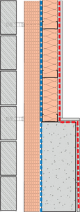
Figure 4.1
Concrete frame and light gauge steel (left).

Figure 4.2
Concrete frame with concrete block infill (centre).
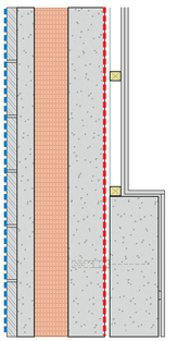
Figure 4.3
Precast concrete panels (right).
Summary
Advantages
- » Excellent structural properties.
- » Common around the UK for residential use over four storeys.
- » Concrete is airtight.
- » High mass if exposed internally.
Disadvantages
- » Quality is difficult to achieve and check.
- » Partial fill insulation commonly has gaps and ‘thermal bypass’ rendering insulation useless.
- » Thermal bridges common.
- » Airtightness is difficult with plasterboard finish.
- » Rigid boards are difficult to install without gaps.
- » Light steel frame infill creates thermal bridges.
Recommendations
- » Quality needs to be closely monitored.
- » Specify continuous insulation where possible, with no gaps between boards / insulation.
- » Minimise amount of steel fixings and brackets that penetrate the insulation layer.
- » For improved thermal performance and airtightness, consider alternatives to light steel gauge infill like blockwork with a pargecoat (Figure 4.2) or pre-cast concrete panels (Figure 4.3).
Common Problems
- » Insulation is missing – commonly at the separating floor, or where shelf angles are used to support bricks at high levels and create additional thermal bridging (Figure 4.8).
- » Rigid insulation boards are cut short at junctions, cavity closers, lintels, cavity trays and services (Figure 4.5).
- » Some instances of unaccounted bridges, by beams, e.g.canopies.
- » Steel stud (LGS) content is greater than SAP assumptions. The percentage of steel content in walls is underestimated, so the heat loss in higher than expected (Figure 4.6).
- » Insulation between steel studs is loose and with gaps (Figure 4.7).
- » U-values are optimistic and not achievable around columns or slab edges.

Figure 4.4
Rigid insulation is difficult to install without gaps.
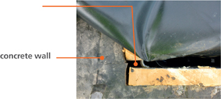
Figure 4.5
Rigid board insulation installed with air gaps. concrete wall
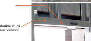
Figure 4.6
Steel content is higher than in U-value calculations. double studs are common

Figure 4.7
Insulation is punctured by steel wall ties.
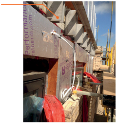
Figure 4.8
Shelf angles used to support brick.
Good Practice
The rest of this chapter highlights good practice detailing for concrete frame with an emphasis on thermal performance. The locations of these junctions are shown in this section drawing through a typical apartment block. The most significant external envelope details affecting heat demand are drawn with good practice airtightness and continuous insulation where practical. Heat loss is calcuated and psi-value provided where useful for SAP calculations.
Normal construction practice with light gauge steel is to have the airtightness layer as the plasterboard and VCL. This means airtightness is difficult to achieve and is vulnerable to surface penetrations. For better airtightness, consider moving the airtightness layer towards the outside of the construction with an airtight breather membrane.
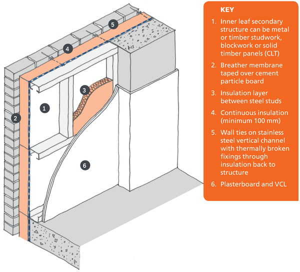
Figure 4.9
3d drawing showing good practice for concrete frame and steel infill construction.
Details
This section through a typical apartment block shows the most significant details affecting thermal performance that are illustrated in more detail in the rest of this chapter.
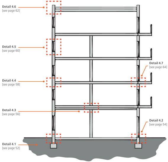
Figure 4.10
Section drawing through apartment block showing the most significant details for energy efficiency covered in this chapter.
Detail 4.1 Ground Floor / Wall
Light gauge steel acts as infill walls for the concrete frame, and must be insulated externally with a rigid board or wool insulation. Airtightness is provided by the VCL, which is vulnerable to be damage. For improved airtightness, use the breather membrane on the outside of the frame.


Figure 4.11
Ground floor heat flux diagram corresponding to Detail 4.1 (opposite).
Heat flux diagram and psi-value
This heat flux diagram models the heat loss through the ground floor and external wall construction. The junction has a psi-value of 0.101 W/m.K, which is a 68% improvement compared to the default value of 0.32W/m.K. The temperature factor is above the critical value of 0.75 and so there is no risk of condensation or mould growth.
| SAP Appendix K Reference | E5 |
|---|---|
| psi-value | 0.101 W/m.K |
| temperature factor | fRsi = 0.83 |
| approved value | 0.16 W/m.K |
| default value | 0.32 W/m.K |
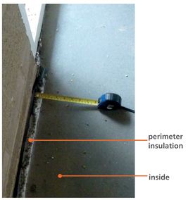
Figure 4.12
Perimeter insulation should be sufficient thickness and not be bridged by screed (left).
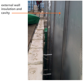
Figure 4.13
Cavities minimum 50 mm clear of debris. Wall tie track system to minimuse thermal bridging (right).
Detail 4.2 Level Threshold
The external door threshold is a difficult area to insulate and so thermal bridging occurs. Prevent this with a thermal break on all sides of the door construction as shown below.


Figure 4.14
3D illustration of level threshold for external door demonstrating the importance of positioning the thermal break in line with the door frame and cavity wall insulation to the side.

Figure 4.15
Door threshold before doorset is fitted (left).
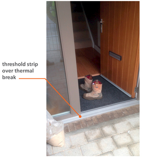
Figure 4.16
Complete door installation and finishes (right).
Detail 4.3 Separating Floor and Wall
This party wall detail has acoustic, fire and thermal performance requirements. Full fill insulation needs to be specified to prevent heat loss through to the corridor.


Figure 4.17
Heat flux through separating floor and wall corresponding to Detail 4.3 (opposite).
Heat flux diagram and psi-value
This heat flux diagram shows heat flow through the party wall and separating floor. When the shelter factor is applied, the detail has a psi-value of 0.181 W/m.K, which is a 24% reduction in heat loss compared to the default value of 0.24 W/m.K. The temperature factor is above the critical value of 0.75 so there is no risk of condensation or mould growth.
| SAP Appendix K Reference | E24 |
|---|---|
| psi-value | 0.181 W/m.K |
| temperature factor | fRsi = 0.84 |
| approved value | N/A |
| default value | 0.24 W/m.K |
Shelter factor is applied with one corridor and three dwellings.
Total heat loss from junction is 0.542 W/m.K, but a psi-value of 0.181 W/m.K should be applied to each flat.

Figure 4.18
Lightweight steel stud party wall must be fully filled with mineral wool.
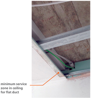
Figure 4.19
Concrete soffit with suspended ceiling zone for services and layer of mineral wool. A deeper ceiling zone with space for circular duct will improve performance of ventilation system.
Detail 4.4 Separating Floor and External Walls
Ensure the fire barrier, cavity tray and brick supports and co-ordinated with the thermal insulation. Brick shelves should be thermally broken and calculated in the psi value. The cement particle board can alternatively be taken over the concrete and taped airtight.

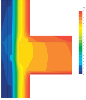
Figure 4.20
Heat flux diagram of separating external wall corresponding to Detail 4.4 (opposite).
Heat flux diagram and psi-value
This heat flux diagram shows heat flow through the external wall at intermediate floor level. The detail does not account for brick angles which increase the heat loss. It has a psi-value of 0.046 W/m.K, which is a 67% reduction in heat loss compared to the default value of 0.14 W/m.K. The temperature factor is above the critical value of 0.75 so there is no risk of condensation or mould growth. The psi calculation assumes there is no brick support bracket at floor level. With a steel brick bracket, the psi-value increases to 0.213 W/m.K. The total heat loss is 0.092 W/m.K. As there is a flat either side of the party floor, a shelter factor of 0.5 has been applied.
| SAP Appendix K Reference | E7 |
|---|---|
| psi-value | 0.046 W/m.K |
| temperature factor | fRsi = 0.87 |
| approved value | 0.07 W/m.K |
| default value | 0.14 W/m.K |

Figure 4.21
External wall with brick tile cladding above full brick with insulation and cill over cavity tray (left).

Figure 4.22
Continuous insulation at junctions and up to windows and doors (right).
Detail 4.5 Windows
For improved performance and build-ability, specify a full width cavity closer with half brick reveal instead of a full brick reveal. Consider installing extra insulation on the internal or external reveals for improved psi value.


Figure 4.23
Heat flux diagram corresponding to Detail 4.5 window jamb (opposite).
Heat flux diagram and psi-value
There are three psi-values to be calculated for a window: the jamb, cill and lintel. This heat flux diagram shows heat flow through the window jamb (plan detail). This junction has a psi-value of 0.051 W/m.K, which is a 49% improvement compared to the default value of 0.1 W/m.K. The lintel psi-value is 0.038 W/m.K which is a 96% reduction in heat loss compared to the default value of 1 W/m.K.
| SAP Appendix K Reference | E4 Jamb | E3 Sill | E2 Lintel |
|---|---|---|---|
| psi-value | 0.051 W/m.K | 0.039 W/m.K | 0.038 W/m.K |
| temperature factor | fRsi = 0.95 | fRsi = 0.95 | fRsi = 0.95 |
| approved value | 0.05 W/m.K | 0.04 W/m.K | 0.3 W/m.K |
| default value | 0.1 W/m.K | 0.08 W/m.K | 1 W/m.K |

Figure 4.24
Aluminium cill with full brick reveal (left).
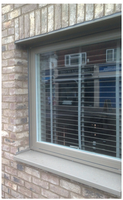
Figure 4.25
Window set back to be in line with insulation layer (right).
Detail 4.6 Roof Parapet
The roof parapet can be a significant thermal bridge if it is not thermally broken as shown below. A common alternative is to wrap the concrete upstand with insulation, which increases material, cost and heat loss.

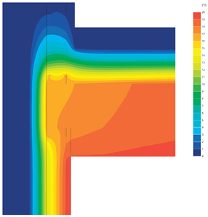
Figure 4.26
Heat flux diagram corresponding to Detail 4.6 (opposite).
Heat flux diagram and psi-value
This heat flux diagram shows heat flow through the roof parapet. A thermal break has been specified to reduce heat flow through the concrete parapet and to remove the need for insulation wrapping the parapet.
This psi-value is 0.075 W/m.K, which is an 87% reduction in heat loss compared to the default value of 0.56 W/m.K. The temperature factor is above the critical value of 0.75, and so there is no risk of condensation or mould growth.
| SAP Appendix K Reference | E15 |
|---|---|
| psi-value | 0.075 W/m.K |
| temperature factor | fRsi = 0.94 |
| approved value | N/A |
| default value | 0.56 W/m.K |
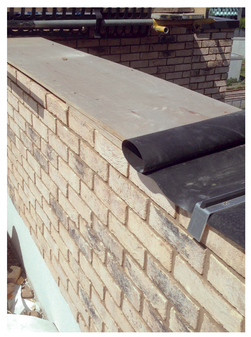
Figure 4.27
DPC on plywood before parapet coping is installed (left).


Figure 4.28 a & b
Parapet thermal break installed (right).
Detail 4.7 Cantilevered Balcony
Cantilevered balconies must be thermally broken to reduce thermal bridging. For improved performance, specify independently supported balconies.

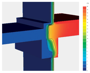
Figure 4.29
Heat flux diagram corresponding to Detail 4.7 (opposite).
Heat flux diagram and psi-value
This heat flux diagram shows heat flow through the concrete balcony. A thermal break reduces heat flow through the concrete cantilevered balcony. This psi-value is 0.326 W/m.K, which is a 67% reduction in heat loss compared to the default value of 1 W/m.K. The psi-value based on 3D calculation of 80 mm concrete to concrete thermal break.
| SAP Appendix K Reference | E23 |
|---|---|
| psi-value | 0.326 W/m.K |
| temperature factor | fRsi = 0.79 |
| approved value | N/A |
| default value | 1.00 W/m.K |

Figure 4.30
Thermal break being installed to separate cantilevered balcony.