Insulated concrete formwork (ICF) comprises interlocking hollow insulation blocks to make a formwork for in-situ reinforced concrete to be poured in the centre. It is quicker and easier than solid masonry construction and offers a good level of performance and design flexibility. It is popular in Europe and the USA with 8% of market share7 and has been growing in the UK self-build market owing to its speed and ease of construction. Hollow lightweight blocks are made from different insulation types, commonly expanded polystyrene or wood fibre which interlock to create a permanent formwork for the concrete. Concrete is poured into the empty blocks every 3 metres high, and can be reinforced for multistorey developments. The concrete forms the airtight layer and continuous insulation is easy to achieve with simple detailing.
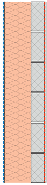
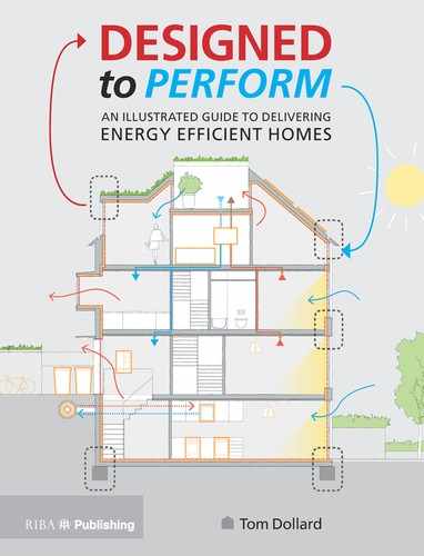
Figure 6.1
Solid masonry, externally insulated and rendered (left).
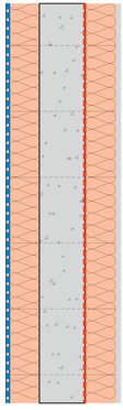
Figure 6.2
Insulated concrete formwork with render external finish (centre).

Figure 6.3
ICF block (top right).
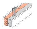
Figure 6.4
Insulation blocks with concrete pour (bottom right).
Summary
Advantages
- » Speed of construction.
- » Simple system suitable for self-build.
- » Excellent airtightness potential.
- » Thermal mass potential with wood fibre blocks and plaster finish.
- » Longevity and robustness of concrete.
- » Can be EPS or wood fibre blocks.
Disadvantages
- » High cost of material.
- » Requires significant amounts of steelwork and concrete for structural reasons.
- » Requires specialists advice/tools to expand/remodel the house in the future.
Recommendations
- » Ensure concrete around steel reinforcements is fully vibrated to ensure full compaction.
- » To ensure its longevity, PVC cable should be kept from direct contact with polystyrene by placing it inside plastic conduit in concrete.
- » Engage with manufacturer early on.
- » Do not pour high lifts as pressure of concrete can burst sides.
- » Keep geometry simple and rectilinear where possible.
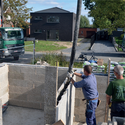
Figure 6.5
Pouring concrete into formwork (left).
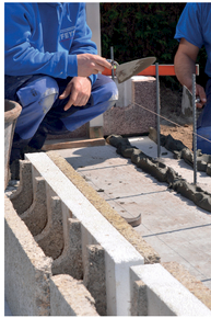
Figure 6.6
Laying first course of blockwork onto steel reinforcement (right).
Common Problems
- » Concrete is airtight, but depends on quality and speed of pouring process.
- » Hollow areas in the concrete can reduce strength of wall, wind-tightness and airtightness.
- » Significant amounts of steel brackets cause thermal bridging at junctions.
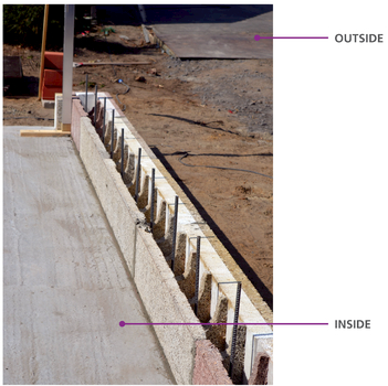
Figure 6.7
Lay blockwork to create formwork around steel reinforcement.
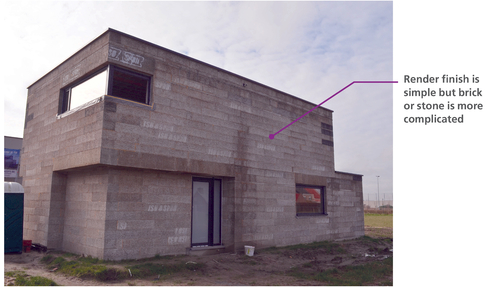
Figure 6.8
ISOSPAN ICF blocks for a house, waiting to be rendered white.
Detail 6.1 Leve Threshold
This ground floor construction is good practice and should be specified when ground conditions allow.
The ground floor concrete raft is poured onto a rigid insulation formwork which allows continuous insulation and minimal thermal bridge at ground floor perimeter.


Figure 6.9
3D illustration of level threshold for external door demonstrating the importance of positioning the door in line with the insulation underneath and to the side.
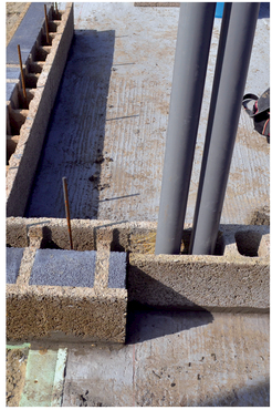
Figure 6.10
Level external door threshold (left).

Figure 6.11
Recessed door opening in external wall (right).
Detail 6.2 Window
The concrete is the airtightness barrier so the window frames should be taped to the concrete. Internal and external insulation to the reveals mean this detail performs 98% better than the normal default detail.

Psi-value
There are three psi-values that should be calculated for a window but the window sill and lintel have the most significant reductions, e.g. this lintel detail has a psi-value of 0.013 W/m.K which is a 98% reduction from the default value.
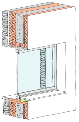
Figure 6.12
3D illustration of the window installation. The window should be taped to the concrete to provide a robust airtight layer.
| SAP Appendix K Reference | E3 sill | E2 lintel |
|---|---|---|
| psi-vaiue | 0.049 W/m.K | 0.013 W/m.K |
| temperature factor | fRsi =0.95 | fRsi = 0.98 |
| approved value | 0.04 W/m.K | 0.3 W/m.K |
| default value | 0.08 W/m.K | 1 W/m.K |

Figure 6.13
Door lintel (left).

Figure 6.14
External wall ready for concrete pour (right).
Detail 6.3 Sunscreen and Door Heads
Sunscreens, louvres or canopies need to be fixed back to the structure. This thermal bridge can be prevented by designing a separate supporting structure or by specifying a thermal break.

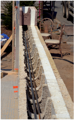

Figure 6.16
Window head and jamb (top right).

Figure 6.17
Large door opening – lintel and temporary support (left).
Detail 6.4 Green Roof Parapet
A low roof parapet should be fully wrapped with continuous insulation. Airtightness is provided by the concrete and taped at junctions.


| SAP Appendix K Reference | E15 |
|---|---|
| psi-value | 0.099 W/m.K |
| temperature factor | fRsi = 0.96 |
| approved value | N/A |
| default value | 0.56 W/m.K |
Psi-value
The psi-value for this detail is 0.099 W/m.K, which is an 82% reduction in heat loss compared to the default value of 0.56 W/m.K.
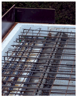
Figure 6.19
Steel bar reinforcement in roof (left).

Figure 6.20
Roof after completion of concrete pour (right).