System Requirements
Robert Oshana, Director, Software Research and Development, Digital Networking, Freescale Semiconductor
This chapter will give readers a number of best practices to improve the quality of the requirements elicitation and development process in their organization. Formulation of high quality requirements (complete, concise, accurate, modular, prioritized, analyzed, verified, and testable) reduce project risk, improve product quality, and allow for effective control of requirements volatility, which increases the likelihood of a successful project.
Keywords
Systems engineering; requirements; use case; functional; nonfunctional; framing; elicitation; constraints; framing; domain; boundary
Definitions
System requirements engineering aims to deliver the right product to the right customer at the right time for the right price. System requirements engineering determines the true customer needs and specifies them completely and correctly. This approach is intended to:
• achieve high customer satisfaction,
• reduce rework and improve productivity within development,
• control scope creep and requirements changes in the project, and
• reduce maintenance and support costs of the delivered system.
The IEEE Definition of a Requirement is [1]:
• a condition or capability needed by a user to solve a problem or achieve an objective,
• a condition or capability that must be met or possessed by a system or system component to satisfy a contract, standard, specification, or other formally imposed document,
• a documented representation of a condition or capability as in definition (a) or (b).
Fred Brooks, in his article “No Silver Bullet: Essence and Accidents of Software Engineering” states, “The hardest single part of building a software system is deciding precisely what to build. No other part of the conceptual work is as difficult as establishing the detailed technical requirements, including all the interfaces to people, to machines, and to other software systems. No other part of the work so cripples the resulting system if done wrong. No other part is more difficult to rectify later” [2].
We can further refine the definition of requirements engineering as a set of activities to identify and communicate the purpose of a proposed system, and the contexts in which it will be used. Requirements engineering acts as the bridge between the real world needs of stakeholders, including users, customers, sponsors, administrators, and other constituencies affected by a system, and the capabilities and opportunities afforded by these technologies.
Developing and managing requirements
Requirements engineering consists of a requirements development phase and a requirements management phase, as shown in Figure 6.1. Requirements development can further be classified into:
• elicitation—techniques for determining the requirements,

Figure 6.2 shows another view of requirements development versus requirements management. Requirements development has key stakeholders, such as marketing, customers, and users, provide input as to the system function and then engineers create the requirements. The team then makes these requirements the baseline. After this, they analyze, document, review, and negotiate further changes to the requirements through a disciplined change control process with input from the same key stakeholders, as well as other key project personnel.

Customer interpretation of requirements
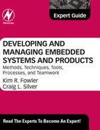
It is important to understand how a customer will interpret documented requirements. Table 6.1 summarizes the expectations from a customer on having documented requirements.
Table 6.1
Spoken versus unspoken inputs from the customer during requirements development
| Requirement | Spoken | Unspoken (Functional) | Unspoken (Delights) |
| If present | Customer is pleased | Customer expects it to be there, takes it for granted | Customer is pleasantly surprised |
| If absent | Customer is dissatisfied | Customer is dissatisfied | Customer is unaffected |
Requirement categories
There are three primary categories of system requirements: functional, nonfunctional, and architectural. Functional requirements are “what” the system should do. Nonfunctional requirements are “how well” the system should perform in one or more areas. Architectural requirements are more descriptive of “connections” between the subsystems to form the final system.
Functional versus nonfunctional requirements
Functional requirements specify what the system has to do. They are traceable to a specific source, often to Use Cases or Business Rules. They are often called “product features.”
Nonfunctional requirements are mostly quality-related requirements which include the areas of performance, availability, reliability, usability, flexibility, configurability, integration, maintainability, portability, and testability. This category may also include implicit requirements for modification and upgrades, reusability, and interoperability.
Table 6.2 shows the importance of nonfunctional requirements to different stakeholders.
Availability is an indicator of the planned up time where the system is available for use and fully operational. Availability is the mean-time-to-failure (MTTF) for the system divided by the sum of the MTTF and the mean-time-to-repair the system after a failure occurs. Availability encompasses reliability, maintainability, and integrity [4].
Efficiency measures how well the system uses processor capacity, disk space, power, memory, or input/output (I/O) communication bandwidth [5]. It also measures the system’s capability to convert mechanical and electrical energy.
Flexibility measures how easy it is to add new capabilities to the product. You might refer to it as augmentation, extensibility, extendability, or expandability.
Integrity relates to security. This quality requirement category describes what is required to block unauthorized access to certain system functions, how to prevent information loss, how to ensure that the system is protected from virus infection, and how to protect the privacy and safety of data entered into the system.
Interoperability defines the ease in which the system can exchange data or services with other systems.
Reliability defines the probability of the system operating without failure for a specific period of time. Ways to measure system reliability include the percentage of operations that are completed correctly and the average length of time the system runs before failing [6].
Robustness, or “ fault tolerance,” is the degree to which a system continues to function properly when presented with invalid inputs, or defects in connected software or hardware or mechanical components, or unexpected operating conditions. System robustness can be viewed as an aspect of reliability.
Usability, or “ ease of use,” refers to the many factors that constitute what users often describe as user-friendliness.
Maintainability measures how easy is it to correct a defect or modify the system. It depends on how easily the system can be understood, changed, and tested.
Portability addresses the effort required to migrate a system component from one operating environment to another. Portability may include the ability to internationalize and localize a product and has aspects similar to reusability.
Reusability defines the effort involved to convert a system component for use in other applications. Lack of reusability leads to systems that are more costly to develop. Reusable systems are modular, well documented, independent of a specific application and operating environment, and somewhat generic in capability.
Testability or verifiability is an important class of requirement. This class of requirement addresses the ease with which system components or the integrated product can be tested for defects. This is very important for complex algorithms and logic, as well as subtle functionality interrelationships.
Table 6.2
Nonfunctional requirements and their importance to users and developers
| Important Primarily to Users | Important Primarily to Developers |
| Availability | Maintainability |
| Efficiency | Portability |
| Flexibility | Reusability |
| Integrity | Testability |
| Interoperability | |
| Reliability | |
| Robustness | |
| Usability |
Performance requirements define how well or how efficiently the system must perform specific functions. Examples of performance might include:
– how fast your motorcycle with a computerized engine management system goes down the road.
– how much water a sump pump with an embedded motor driver pulls out of a basement.
• I/O—e.g., frames per second through a video port.
– concurrent usage loads or channels of execution, or
– how much load your power jack with an embedded controller can hold without dropping a car on your head.
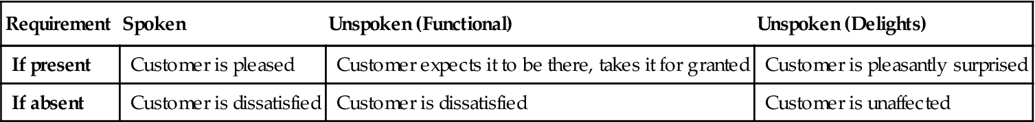
Figure 6.3 shows the relationship between functional and nonfunctional requirements.
System architecture requirements
Another important class of system requirements relates to system architecture. Examples of this class of requirements include:
• Component-naming—be consistent in naming components (mechanical, hardware, or software). This makes systems easier to understand.
• Compatibility—many systems need to be compatible with other systems. A hotel reservation system, for example, needs to be compatible with several financial systems.
• Ease of interfacing—this relates to coupling. Systems should be loosely coupled, which means that system components can operate properly without having intimate knowledge of the workings of other system components.
• Upgradability—systems that have a high probability of later revisions should be designed to support easy upgrades.
• System building—the activity of creating new systems by using tools to build new mechanical, hardware, or software definitions. For systems that will change often, this process needs to be made easy.
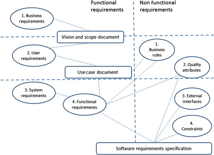
Systems live within the context of the real world, and the real world has constraints. Otherwise, with no constraints, there are an infinite number of ways to solve the problem. Reducing the number of available options often eases the job of designing systems by limiting the degrees of freedom when creating a new system. Table 6.3 shows several classes of system constraints and some examples of each.
Requirements’ attributes
System requirements also have key attributes that can measure how well each requirement is written. Table 6.4 lists these key attributes. Please note: there are many nonfunctional requirements and not all of them can be a primary focus due to system constraints.
Table 6.4
Key attributes of requirements
| Requirement Attribute | Definition |
| Correct | According to the customer or stakeholder representative. |
| Necessary | Requirement must be feasible. Tools, techniques, resources, budget must be able to satisfy the requirement. |
| Prioritized | Should be prioritized by developers and stakeholders. Performed during the interview or elicitation phase. Should be able to trace back to a use case. |
| Unambiguous | There is only one interpretation. The requirement is easy to read and understand. |
| Concise | The requirement only contains the information needed to proceed to the next development step. |
| Verifiable | The requirement must be testable and measurable. A person or machine is able to confirm that the system meets the requirement. |
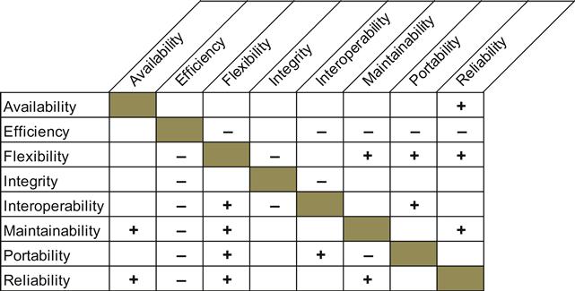
As shown in Figure 6.4, nonfunctional requirements have impacts on each other. Increasing the focus on one nonfunctional requirement, such as reliability, has a positive impact on other nonfunctional requirements such as availability. On the other hand, increasing the focus on flexibility, for example, may adversely affect the nonfunctional requirement of efficiency. This needs to be considered when formulating and prioritizing nonfunctional requirements.
Common risks in setting requirements
When specifying system requirements, there are some common risks that must be considered:
• Insufficient User Involvement: this leads to unacceptable products.
• Creeping User Requirements: this contributes to budget and schedule overruns and leads to a decline in overall product quality.
• Ambiguous Requirements: this results in ill-spent time and rework.
• Inappropriate Features: usually this is done by developers or users and leads to unnecessary features to address extraneous or low-priority desires or concerns.
• Minimal Specification: this leads to missing key requirements.
• Overlooked User Classes: which leads to dissatisfied customers.
• Inaccurate Planning: this is often caused by incompletely defined requirements.
Process and QA
Chapter 1 introduces processes and standards for Quality Assurance (QA). In this chapter, I will only focus on Capability Maturity Model Integration (CMMI) to serve as an example process and standard under which requirements might develop.
The CMMI is a process improvement framework and appraisal program. The CMMI is required by many projects for the Department of Defense, as well as commercial companies, for system development (but it can be used for general system development, too). CMMI can be used to guide process improvement across a project, division, or an entire organization. CMMI processes are rated according to their maturity levels, which are initial, repeatable, defined, quantitatively managed, optimizing as described in Chapter 1. The five maturity levels of CMMI are based on a strong foundation of requirements at Levels 2 and 3 as fundamental processes to support the standard.
At process area Level 2 (Managed), Requirements Management is a key process area. Requirements Management is the capability that helps an organization achieve more predictable and less chaotic projects. One key activity within Level 2 is collecting and documenting requirements. This doesn’t mean that an organization should wait until achieving Level 2 before collecting and documenting requirements. Collecting and documenting requirements is profitable at any level and will help the organization climb through the levels of CMMI.
At process area Level 3 (Defined), Requirements Development is required. Requirements Development is performed after an organization has adopted the discipline of managing requirements changes and tracking status. The focus is on developing high-quality requirements.
The key themes of the CMMI relating to requirements include:
• The development team understands requirements and resolves issues with customers.
• Maintains traceability and bidirectional traceability of requirements.
• Records the source of lower level or derived requirements.
• Traces each requirement downward into derived requirements and its allocation to functions, object, processes, and people.
• Establishes horizontal links from one requirement to another of the same type.
There are three sets of practices to perform during requirements analysis:
1. Identify a complete set of customer requirements to develop product requirements. Elicit stakeholder needs and transform those needs and constraints into customer requirements.
2. Define a complete set of product requirements. The three key steps are establish product components, allocate requirements to product components, and identify interface requirements.
3. Derive child requirements, and understand and validate those requirements. The five key steps are establish the operational concepts and scenarios, define the required system functionality, analyze the derived requirements, evaluate product cost, schedule, and risk, and validate requirements.
Domains and properties
You can analyze a system from the perspective of an application domain, as well as from the perspective of a machine domain. We write the requirements in the application domain. We then implement the system in the machine domain. Figure 6.5 illustrates these domains in abstract form.
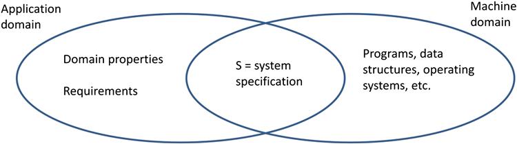
In Figure 6.5, the domain properties define the things in the application domain that are true whether or not we ever build the system.
The requirements are those things in the application domain that we wish to be made true by delivering the proposed system. These may also involve phenomena to which the machine has no access. For example, a trucking navigation application that must control where trucks drop off and pick up cargo does not have direct access to the environment the truck is in but must control the truck navigating in that environment.
The specification is the description of the behaviors that the system must have to meet the requirements. These can only be written in terms of shared phenomena of the system. The shared phenomena for the trucking example mentioned above would be the user interface to the computer system. This interface would include capabilities to be able to navigate the truck in the environment.
Setting boundaries
When eliciting requirements, the first thing is to set the boundaries. For example, how will the system interact with the world? Asking that question will help set a boundary. The requirements engineer must decide what phenomena are shared in the application domain. One approach is to use the four-variable model, developed by Parnas and Madey, as shown in Figure 6.6 [7]. Here we decide the boundaries by designing the input/output devices. Then we use I/O data items as proxies for the monitored and controlled variables for the system we are specifying.

Van Lamsweerde describes this as an extension to the four-variable model when it comes to describing requirements as shown in Figure 6.7 [8].

Van Lamsweerde’s satisfaction argument for system requirements is then presented as:
and defined as:
if the software requirements in set SOFREQ are satisfied by the software, the assumptions in set ASM are satisfied by the environment, the domain properties in set DOM hold and all those statements are consistent with each other, then the system requirements SysReq are satisfied by the system.
Framing the system for requirements definition
Ben Kovitz, in his book, “Practical Software Requirements” describes a set of problem frames used to help frame a system to better understand the requirements [9]. He defines five problem frames as given in Table 6.5. Let’s briefly discuss each of these.
Table 6.5
Five problem frames used for system requirements elicitation and definition [9]
| System Requirement Type | Description | Problem Frame |
| Queries | Requests for information from the application domain | Information |
| Behavioral rules | Rules according to which the problem domain is to behave | Control |
| Mappings | Mappings between data input and output | Transformation |
| Operations on realized domains | Operations what users can perform on objects that exist inside the software | Workpiece |
| Correspondence between domains | Keeping domains that have no shared phenomena in corresponding states | Connection |
Information problems
This type of problem primarily answers queries about a certain part of the real world and the requirements describe types of information requests to be satisfied. The requirements need to address how the system can get access to that part of the real world. This means describing those relevant parts of the world, the queries necessary to get that information, as well as the people or things that initiate those queries.
In these types of systems, the requirements should be able to satisfy the queries initiated by information requestors. These types of information systems report on the state of the world but not change its state. In other words there is no causation. Examples of information systems include most inventory control systems, search engines, and Global Positioning System (GPS) mapping systems.
Information problems can be categorized as dynamic systems which query and report information that changes, for example, stock quotes, and static systems where the information does not change often, such as a city map.
Information systems can be passive systems where the queries are initiated by the user, such as an audio system providing explanations for museum displays, or active systems where the information is supplied without being asked, such as a burglar alarm system. If a query is triggered by an event, such as inventory running low or a warning light, then we need to document further the requirements of what triggers these notifications, what kind of performance (e.g., response time) is required, and how to determine that the information was received properly.
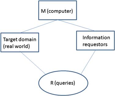
In an information system, the requirements specification must describe the model of the real world for which you are making inquiries. Figure 6.8 shows a simple frame diagram of an information problem. This diagram shows:
• The requirement category, R (queries in this case)
• The target domain (in this case the real world we are attempting to model)
• The entity querying for information (the information requestors).
Most information systems require some method to relay information from the real world to the software, for example, people performing data entry. This leads to inefficiencies that you must consider as well. For example you may need additional requirements that check for errors in data entry from users. This is shown in Figure 6.9. The data entry user “connects” the computer system to the information requestors. Whenever you have a connection domain like this (very common in computer systems), this introduces two inefficiencies:
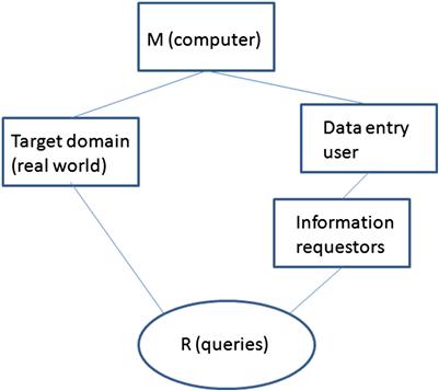
You may need to formulate additional requirements to address this distortion and delay introduced by this connection domain.
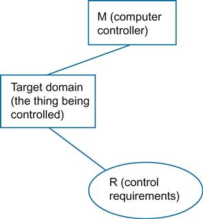
Control problems
Unlike information systems, control systems focus on causation. This means that control systems interact with the world around them rather than just extracting information from the environment.
Control systems require that you document what is responsible for ensuring that some part of the real world behaves in accordance with a set of rules. Your requirements must describe those things that inhabit that part of the world that the rules obey. Requirements for control systems describe how the system will monitor that part of the world and initiate causal chains that cause the specified rules to behave correctly.
Because control systems interact with the world, the focus of requirements for control systems should describe the following:
• The causal properties of those relevant parts of the world applicable to what you are trying to control.
• The rules that the system components follow to achieve this control.
• Any important and relevant phenomena shared between the computer system and the problem domain (the real world).
Examples of control problems are heating ventilating and air conditioning (HVAC) systems and traffic lights. Figure 6.10 shows a simple frame diagram of a control system.
Control systems can also have connection domains. For example, control systems can direct people to perform certain types of activities like taking a receipt to a manager or calling in a prescription. This leads to the same forms of distortion and delay that a control system may solve with additional requirements and constraints.
Requirements for control systems need to specify the behavioral rules for the shared phenomena. In addition, timing rules must be well documented.
Transformation systems
Transformation systems convert some form of input data to output data based on a set of rules or algorithms. The requirements for transformation systems must describe the entire set of all possible inputs and the mapping rules that indicate, for each possible input, the correct output. Figure 6.11 is a frame diagram of a transformation problem.
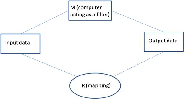
The requirements for transformation systems describe all possible inputs, the possible outputs, and the rules relating each possible input to its corresponding output. The rules are referred to as the “mapping.” Examples of transformation systems include bar scanners at supermarkets that read bar codes and translate into product and price (e.g., bar codes to numbers), and image processing software that takes a video frame and enhances the image or performs edge detection on the image. The algorithms that perform these functions are the primary requirements that must be documented.
Workpiece
Workpiece systems are systems where the application serves as a tool for creating objects such as files of databases that exist within the software in the system itself, like memory or a hard disk.
Requirements for workpiece systems describe the objects that must exist within the computer, as well as the operations that users can perform on these objects.
The system helps users create the objects of interest. These can be documents, designs, databases, and other forms of electronic media that exist inside the computer. There may also be requirements that allow these objects to be printed, so in a sense, the objects can “exist” outside the computer, as well.
These workpieces are usually created using a user interface, so requirements for workpiece problems must also describe the user interface operations required to produce the workpieces.
Connection
Connection domains “connect” application domains that, for some reason, cannot be connected directly. The goal is to make them appear to be connected. An ideal connection is rarely possible so a connection domain would set an upper limit as to how well the requirements can be fulfilled. Each connection domain adds a level of distortion and delay between the two domains that you are trying to connect. In Figure 6.9, for example, the data entry clerk is a form of connection domain. The distortion in the data entry clerk is entering the wrong data into the system. The delay component represents the finite amount of time to enter the data into the system.
Other examples of connection domains include a video conferencing system that connects two domains of interest in different cities. There is obvious distortion (video signal not ideal) and delay (in the transmission of video and audio between the sites). The requirements engineer must be able to identify one or more connection domains in the system and, for each one, determine the distortion and delay, their upper limits, and then determine if additional requirements must be derived to determine if the connection domain is not operating properly (e.g., the data entry clerk is entering the wrong data), and be able to correct (e.g., provide range checking).
Use cases
Use cases provide an important technique for eliciting requirements. A use case describes, at a high level, “what” the system will do, not “how” the system will achieve a particular behavior. More to the point, a use case is not a design description of the system. A use case has a user focus for the purpose of scoping the project and giving the application some structure. Use cases can be detailed in “scenarios” that identify a particular thread of system usage in the form of a written narrative. Doing so shifts the perspective to what users need to accomplish (in contrast to what users want the system to do).
A use case is a discrete, stand-alone activity that an actor can perform to achieve some outcome of value. Use cases capture functional requirements of a system from the perspectives of the different users of the system. Use cases are textual narratives describing the different kinds of scenarios in which the system will be used. A use case diagram helps to visualize which actors are involved in which scenarios. Figure 6.12 is an example of a use case diagram for an Automated Teller Machine (ATM).

Collaborations among objects in the design realize the functional requirements described in use cases. Use cases do not depict nonfunctional (or qualitative) requirements. A use case is a scenario that describes how the system works in a given situation and is defined from an “actor’s” perspective.
An actor is a role played by a person or device as it interacts with the system. An actor is anything that communicates with the system and that is external to the system itself. An actor is outside the system model but interacts with the system. An actor can be a person, machine, or an information system.
By creating use cases, you keep the focus of development on the user and the user’s perception of the system. A nontrivial system will often have many actors, each involved in multiple scenarios.
The first step in identifying use cases is to identify the different people or devices that will interact with the product. Consider what each actor hopes to accomplish by using the product. This can lead to the discovery of new requirements. There can be overlap, in that different actors may expect to use the same system facilities. Be consistent and look for opportunities to represent two similar scenarios with a more general one.
The key questions answered by a use case are:
• What main tasks or functions are performed by the actor?
• What system information will the actor acquire, produce, or change?
• Will the actor have to inform the system about changes in the external environment?
• What information does the actor desire from the system?
• Does the actor wish to be informed about unexpected changes?
A use case scenario is essentially a narrative text describing the sequence of events of an actor, using a system. It can be considered a short story. Think of this as a static model of functionality that describes what happens when an actor interacts with a system. A scenario represents a function that makes sense to an actor. An actor initiates interactions with the system; and vice versa but there is no temporal sequencing with a scenario.
The steps to develop use cases are:
1. Identify who will use the system directly.
3. Define what the actor wants to do with the system, this becomes a use case.
4. For each use case, define what happens.
A scenario is a use case instance. It contains the same steps as the use case. A scenario typically describes just one execution path (one outcome) through the use case. It describes a sequence of actions and interactions of objects. The objects in the scenario are from the classes in the use case (e.g., a particular set of objects acting to cancel a catalog order).
A template for a use case scenario is shown below for an ATM. This template follows the outline given in the DOT/FAA Requirements Engineering Management Handbook [10].
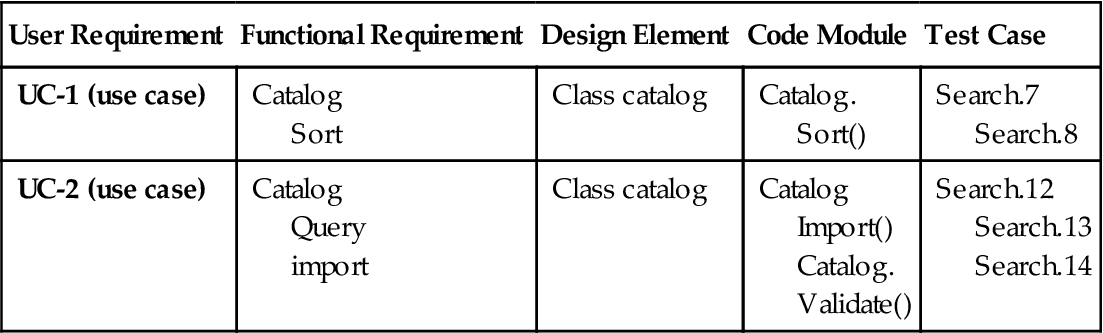
Requirements traceability focuses on documenting the life of a requirement and providing bidirectional traceability between various attributes of a requirement. It enables stakeholders to find the origin of each requirement and track changes to those requirements and other important attributes. Table 6.6 is an example of requirements traceability. It shows the user requirement, described in a use case, and traces it to functional requirements, design elements, code modules, and test cases.
Table 6.6
Example of a traceability matrix for requirements
| User Requirement | Functional Requirement | Design Element | Code Module | Test Case |
| UC-1 (use case) | Catalog Sort |
Class catalog | Catalog. Sort() |
Search.7 Search.8 |
| UC-2 (use case) | Catalog Query import |
Class catalog | Catalog Import() Catalog. Validate() |
Search.12 Search.13 Search.14 |
Prioritizing requirements
Requirements prioritization is done to make sure the product contains the most essential functions and to provide the greatest product at the lowest cost. You must balance project scope against the constraints of schedule, budget, staff resources, and quality goals and drop or defer low-priority requirements to a later release. Establishing priorities early allows for more options. Doing this balances the business benefit of each function against cost. The customers can determine value while considering cost, technical risk, and other trade-offs. Table 6.7 suggests some prioritization levels to be used for prioritization of system requirements.
Table 6.7
Prioritization levels to be used for prioritization of system requirements
| Names | Meaning |
| High | A mission-critical requirement; required for next release |
| Medium | Supports necessary system operations; required eventually but could wait until a later release if necessary |
| Low | A functional or quality enhancement; would be nice to have someday if resources permit |
| Essential | The product is not acceptable unless these requirements are satisfied |
| Conditional | Would enhance the product, but the product is not unacceptable if absent |
| Optional | Functions that may or may not be worthwhile |
Table 6.8 shows the relationship between urgency and importance in the prioritization of system requirements.
High-priority requirements are both important (the user needs the capability) and urgent (the user needs it in the next release). Contractual or legal obligations might dictate that the requirement must be included, or there might be compelling business reasons to implement it promptly.
Medium-priority requirements are important (the user needs the capability) but not urgent (they can wait for a later release).
Low-priority requirements are not important (the user can live without the capability if necessary) and not urgent (the user can wait, perhaps forever).
Table 6.8
The relationship between urgency and importance in setting priorities for system requirements
| Important | Not Important | |
| Urgent | High priority | Don’t use these |
| Not urgent | Medium priority | Low priority |
Requirements in the fourth quadrant appear to be urgent but they really aren’t important. Don’t waste your time working on these. They don’t add sufficient value to the product.
Prioritizing system requirements should be based on value, cost, and risk. The project manager should perform the following steps to set priorities:
• Adjusts input from the other participants, customer representatives, product champions, marketing staff, or development representatives, such as team technical leads.
When prioritizing requirements use these steps as a guide:
1. List all features, use cases, or requirements.
2. Customer representatives estimate the relative benefit on a scale of 1 (not useful) to 9 (extremely valuable).
3. Estimate the relative penalty if the feature were not included, on a scale of 1 (no one will be upset if it’s excluded) to 9 (a serious downside).
4. Calculate the total value=benefit+penalty (weights can change).
5. Developers estimate relative cost of implementation on a scale of 1 (quick and easy) to 9 (time consuming and expensive).
6. Developers estimate relative degree of technical or other risks on a scale of 1 (easy to program) to 9 (serious concerns).
7. Calculate priority=value%/((cost%*weight)+(risk%*weight)).
8. Sort features in descending order by calculated priority.
Recommendations to reduce requirements’ risks
Here is a summary of the key risks for requirements with some recommendations on how to reduce or eliminate these risks.
1. Risk: Product vision and project scope
• Recommendations: Early on, write a vision and scope document that contains business requirements; use it to guide decisions about new or modified requirements.
2. Risk: Time spent on requirements development
• Recommendations: Record how much effort is actually spent on requirements development for each project; use it to judge whether it was sufficient and improve planning for future projects.
3. Risk: Completeness and correctness of requirements specification
• Recommendations: Elicit requirements by focusing on user tasks. Devise specific usage scenarios, write test cases from the requirements, have customers develop acceptance criteria. Create prototypes; elicit feedback. Have customer reps inspect specs and analysis models.
4. Risk: Requirements for highly innovative products
• Recommendations: Emphasize market research, build prototypes, use customer focus groups for feedback early and often.
5. Risk: Defining nonfunctional requirements
• Recommendations: Query customers about performance, usability, integrity, reliability. Document in the System Requirements Specification with acceptance criteria.
6. Risk: Customer agreement on product requirements
• Recommendations: Determine the primary customers; use a product champion.
7. Risk: Unstated requirements
• Recommendations: Use open-ended questions.
8. Risk: Existing product used as the requirements baseline
• Recommendations: Document requirements discovered through reverse engineering; have customers review them for relevance and correctness.
9. Risk: Requirements prioritization
• Recommendations: Prioritize every functional requirement, feature, and use case; allocate each to a specific system release. Evaluate the priority of new requirements against the body of work remaining.
10. Risk: Technically difficult features
• Recommendations: Evaluate the feasibility of each requirement. Track and watch for those falling behind schedule. Take corrective action early.
11. Risk: Unfamiliar technologies, methods, languages, tools, hardware
• Recommendations: Don’t underestimate the learning curve. Identify high-risk requirements early; allow time for false starts, experimentation, and prototyping.
12. Risk: Requirements understanding
• Recommendations: Conduct inspections and include developers, testers, and customers. Create models and prototypes; represent requirements from multiple perspectives.
13. Risk: Time pressure to proceed despite To Be Determined (TBDs) still remaining in the document
• Recommendations: Record the person responsible for closing and the target date for resolution.
14. Risk: Ambiguous terminology
• Recommendations: Create both a glossary and a data dictionary.
15. Risk: Design included in requirements
• Recommendations: Make sure requirements emphasize what needs to be done rather than how to do it.
Mike Gard: thoughts on developing requirements
Participation by the design team begins at the very earliest stages of the project effort. Design team effort is needed before and during proposal generation, where even nascent product and project ideas are being explored. The idea is not to do a preliminary design at the proposal stage—although that is a wonderful thing to do if circumstances permit. Rather, the very earliest work should identify possible pitfalls, identify design unknowns, carefully assess and rank design priorities, and, if necessary, identify those unknowns that fall into the category of inventions needed (“we must find a way to …”). This is necessary to avoid surprises, of course, but also to make sure budgets for time, money, materials, and manpower are well thought out.
Design trade-off information is especially important in the concept definition stage of embedded systems because project definition must do the following:
• make and clarify expectations about the functions and features to be embedded in circuit hardware,
• clarify expectations about the complementary or mating functions and interfaces external to the embedded design,
• clarify expectations about implementation and partitioning between the mechanical, hardware, software, and firmware components.
Failure to establish these matters early in concept development will often result, at best, in over specification or functional redundancies in the design. At worst, failure to establish these matters will plant the seeds of a catastrophic omission or fundamental, and sometimes fatal, flaw.
In September 1999, the Mars Climate Orbiter (formerly the Mars Surveyor ’98 Orbiter) disintegrated after making an improper low entry into the upper Martian atmosphere because ground-based computer software produced thruster force output in Imperial pound-seconds (lbf*s) rather than the specified newton-seconds (N*s). One section of the final investigation is worth quoting in entirety:
The MCO MIB has determined that the root cause for the loss of the MCO spacecraft was the failure to use metric units in the coding of a ground software file, “Small Forces,” used in trajectory models. Specifically, thruster performance data in Imperial units instead of metric units was used in the software application code titled SM_FORCES (small forces). The output from the SM_FORCES application code as required by a MSOP Project Software Interface Specification (SIS) was to be in metric units of Newton-seconds (N-s). Instead, the data was reported in Imperial units of pound-seconds (lbf-s). The Angular Momentum Desaturation (AMD) file contained the output data from the SM_FORCES software. The SIS, which was not followed, defines both the format and units of the AMD file generated by ground-based computers. Subsequent processing of the data from AMD file by the navigation software algorithm therefore, underestimated the effect on the spacecraft trajectory by a factor of 4.45, which is the required conversion factor from force in pounds to Newtons. An erroneous trajectory was computed using this incorrect data.
The discrepancy between calculated and measured position, resulting in the discrepancy between desired and actual orbit insertion altitude, had been noticed earlier by at least two navigators, whose concerns were dismissed. A meeting of trajectory software engineers, trajectory software operators (navigators), propulsion engineers, and managers, was convened to consider the possibility of executing TCM-5, which was in the schedule. Attendees of the meeting recall an agreement to conduct TCM-5, but it was ultimately not done [11].
If there is a single best guarantor of success, it is the opportunity for designers and system architects to spend time in the customer’s shoes. It is one thing to design to a set of specifications—that is expected. The difficult thing is to make sure the design is being done to the correct specifications; this is to say, that the specifications accurately reflecting what the customer wants and needs. This is not always what the customer’s agent, the contracting authority, or even the customer, originally says is desired. The need to root out the true requirements is most acute when the intended end user is not a technical individual or organization; in those cases the customer often describes needs based on what already exists rather than what is possible. In such cases, the design team needs the insights that come only from actually experiencing, or at least observing, the task requirement at hand. This is not always possible, but it should be a design team priority whenever circumstances allow it. Hands-on experience should be obtained as early and as often as possible during the project.
On occasion, design team recommendations may be articulated but overruled by the customer, the customer’s agent, or other folks within the design team’s organization. This is unfortunate, but it happens. In the commercial marketplace, the marketing strategy may emphasize cost over performance to obtain greater market penetration in the low end (euphemistically called the “value” tier) of the market. In other cases, the ultimate design option may be something simple, intuitive, reliable, extremely durable, and nearly foolproof (military hardware for combat infantry comes to mind), whereas the engineering team (and, more often, the marketing team) sees opportunities to produce something elegant and capable of satisfying very difficult, but relatively rare, problems. In these cases, document everything and forget nothing—there will be other projects and other opportunities to apply what has been learned.
Design requirements often evolve as design effort progresses and functional prototypes get their first customer use. Editor’s Note: See Tim Wescott’s section in Chapter 8 titled, “The Importance of Early Prototypes.” The later the customer begins to experiment with the product, the greater the risk to the schedule and budget. Even the problem known as “creeping elegance” often can be traced to the tendency for large projects to be handled by specialized contracting groups which, themselves, have little or no direct experience with the needs of the true end user. Specification creep, cost overruns, schedule delays, creeping elegance, and poor final performance are the almost inevitable (although predictable and preventable) results.
Military projects are often cited for these issues; they are very expensive and highly visible examples because of their size and complexity. Military projects are hardly unique in their occasional ability to get it wrong. My own work experience encompasses missile, aircraft, ophthalmic ultrasound, geophysical (seismic) systems, computer aided tomography scanners, and construction equipment. Despite differences in technologies and applications, the problems have much in common. More often than not, the ultimate causes of most problems are failures to completely understand the end user’s true needs coupled with vague, high-level, nonspecific definition that cover only a few critical functions. As it inevitably becomes obvious that the specifications are inadequate, there are specification changes to correct the deficiencies. Just as often, these changes in specification are strongly driven by the influence of schedule or budget (because the project is now well advanced) rather than technology or good engineering judgment. All too often, the results of this situation are an unrealistically compressed schedule, design compromises to preserve schedule and money, and an end product that is not all it could or should have been. Invest time and effort up front to develop good specifications—it is much better for all concerned. Good specifications are the essential first step of the design process.
Oshana’s Maxim—estimating requirements’ efforts
In my experience, requirements engineering is a complete lifecycle process that takes between 15% and 25% of the total effort of a complex engineering project to do properly. Nonfunctional requirements formulation (performance goals, usability goals, scalability, etc.) are much harder than functional requirements because analysis, simulation, modeling, research, and benchmarking are required to create well defined, quantifiably correct, measureable, and testable requirements. Multiple iterations of discussion, clarification, and review are needed to drive clarity into the requirements process. Globally distributed development teams and customers exacerbate the problem.
Acknowledgments
I thank Geoff Patch and Tim Wescott for their reviews of this chapter.