
Behavioral coding part II: defines, parameters, enumerated types, and packages
Abstract
Keywords
define
parameter
macro
type
method
Code readability and maintainability can frequently be enhanced through the use of mnemonic names and global text substitutions. Verilog supports several different methods for these techniques, as well as providing for design reuse and scalability.
Global definitions
The compiler directive `define is used for string substitution. Once a macro has been defined, it becomes available throughout the design hierarchy.
As a compiler directive, `define does not follow Verilog language conventions. It does not need to be inside of any module. Unlike a standard line of Verilog code, it is terminated by a new line, not by a semicolon. If a defined macro does conclude in a semicolon, the semicolon becomes part of the text substitution string.
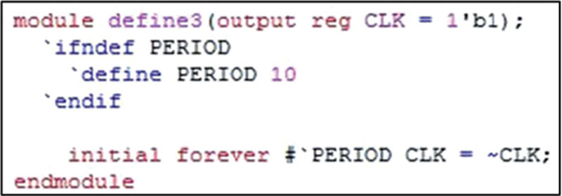
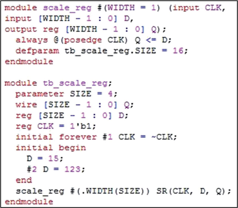
The global nature of defined macros is both a strength and a weakness. Because it has the power to change values in any module at any level of hierarchy, `define must be used with care. A common discipline is to have a single definitions file that all designers on a project reference but that only one person maintains. In this way, values that should be common across the entire scope of the design will remain so and unexpected changes to values in design files avoided. In Figure 4.1, a define macro is created and used inside of a verification module. While syntactically correct, defining this global parameter more centrally may be a better strategy, as PERIOD as defined in this module will be global, possibly overwriting other uses of PERIOD.

Defined macros do not necessarily have a value at all. The act of defining one can provide all the utility needed. This is a technique used in conditional compilation. If a macro is defined, regardless of any value associated with the macro, a section of code will be compiled. Conditional compilation also uses `ifdef, `ifndef, `elsif, and `endif directives. The available define directives are shown in Figure 4.2. In that example, the `elsif clause and the `ifndef clause will work identically. There are two ways of accomplishing the same selection.

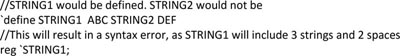
Only one macro can be defined as per use of `define. Attempting to define multiple macros with one use of `define as shown below would result in syntax errors whenever STRING1 was referenced. STRING2 would remain undefined.
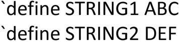
To define both STRING1 and STRING2, the following syntax would work.
In Figure 4.3, if the line `define FAULT is included in the code, the design unit MYDES_FAULTED will be compiled. If it is deleted or commented out, a version without faults will be selected. This technique can be used in verification to determine if a self-checking test fixture is capable of finding inserted flaws. It can also be used to select between different implementations of a design, such as the original source code or a synthesized gate-level representation. Note that FAULT has no value. The only consideration is whether or not it has been defined.

Negative logic also is supported with defined macros: if a macro is not defined, an action that would not otherwise be necessary can be taken. This can be useful in a design environment that is supposed to have a global definitions file but that file may not be implemented at the time when some simulations are run. In Figure 4.4, the period will be defined locally if it has not already been defined, but the local definition will not be made if the period has already been defined elsewhere. That example also uses an initial condition when declaring CLK to be a port and a variable of type reg. While the initial condition assignment would work in simulation, it would be ignored by synthesizers if this technique were used in a hardware design module. Although syntactically similar to implicit continuous assignments, initial assignments to register variables are entirely different in that they are transitory and for simulation purposes only. In contrast, not only is an implicit continuous assignment synthesizable, but the value so assigned will be permanent.
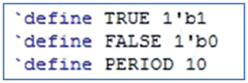
The contents of a sample definitions file are shown in Figure 4.5. Note that it does not need to be in any sort of a module structure. A series of macros is all the file contains.
This file may be referenced by compiling it along with the source code files that will use the definitions. Alternatively, it may be explicitly included in source code files by using an `include directive, as shown in Figure 4.6. Note that the quotation marks are required. The `include directive is not limited to definition files. Any piece of Verilog code may be so referenced, which will cause the code to act as if it were typed into the source code. This technique is most often useful with subroutines where the subroutine code is maintained in its own file but is repeatedly used in other design and verification modules. Subroutines are covered in Chapter 6.

If the code of Figure 4.6 were to be synthesized, only the hardware inferred in the final “always” block would result. The clock generator, including the initial assignment of CLK to logic one, is nonsynthesizable and would be ignored.
A defined macro can be removed from operation by undefining it via the `undef directive. This is shown below.

While some recommend undefining a macro before redefining it to a new value, this author finds that an eccentric exercise. The recommendation here is to never undefine or redefine macros. Their strength is their universality, in that they maintain constant values across the design hierarchy. Undefining and redefining a macro makes the values used dependent on the order of compilation, which is likely to lead to unintended consequences and errors.
Defined macros can take arguments, although this feature is not universally supported. The following example only multiplies together two variables, but the expressions that use the arguments can be arbitrarily complex.

The macro could then be used in a module to form the product of two variables, as shown below.

Because defined macros always end with white space, in traditional Verilog there is no way to use arguments to a macro to concatenate together strings such that the resultant string does not have any white space. SystemVerilog extends the define macro capability by adding a new delimiter that can be used for this purpose. This new delimiter is two-backtick characters. In the example below, use of the macro catname would create variables with the arguments to the macro concatenated together. The result would be the declarations of five-bit register variables alphabravo and charliedelta.

This technique could be used to create a series of variables with different index suffixes. However, use of an array for this purpose would be more common. Arrays are covered in Chapter 3.
Parameters
Parameters are used to create scalable, reusable modules. The default values for parameters may be overridden to create new implementations of old designs as well as to create multiple instances of a design with different sizes or other characteristics.
Parameters differ from defined macros in several ways. A parameter is only available in the module in which it is declared, unlike a defined macro, which is global in scope. Parameters may be changed on an instance-by-instance basis, giving unique values to each instance but leaving all other instances unchanged. Each parameter must have a default value, unlike a defined macro, which can exist without a value at all.
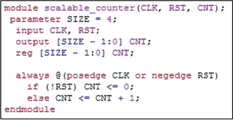
A scalable counter using a parameter is shown in Figure 4.7. If the parameter is not overridden, the counter will be four bits.
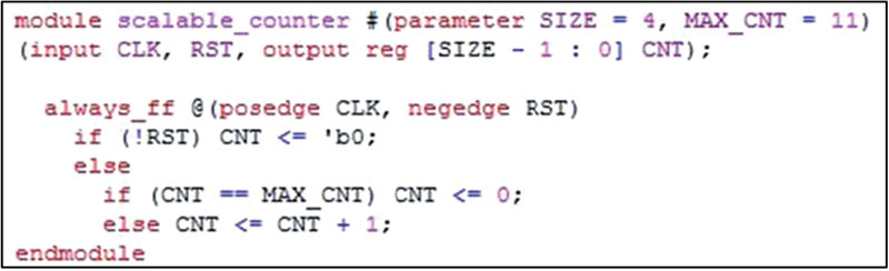
Taking advantage of Verilog 2001 and SystemVerilog extensions, the same counter can be rewritten as shown in Figure 4.8. The two implementations are functionally identical.

Parameters can be referenced throughout the module, not just when establishing size. In Figure 4.9, the point at which the counter rolls over is set with a second parameter.
Unlike variables, parameters are fixed at compile time. This is true for both simulation and synthesis. This is the reason the example of Figure 3.44 remains synthesizable despite the use of a nonsynthesizable operator. The exponential operator there only operates on a parameter, not a variable, so the final value is determined when the module is compiled. This value does not change during operation.
In these examples, the value of each parameter is an integer. The language allows greater flexibility than that. Any type, including strings, may be assigned to parameters, although the utility in circuit design of anything other than an integer is limited at best.
The following parameter declarations are all legal, albeit not useful for hardware description.

Multiple parameters may be declared with a single use of “parameter.” Multiple parameter declarations are shown in the last two examples above. Attempts to do something similar with `define macros would result in compiler errors rather than two macros per line.
Overriding default values
The power of parameters is in their ability to be changed on an instance-by-instance basis. In Figure 4.10, two instances of the scalable counter are made. One will be six bits wide, the other eight. No instance of the default four-bit design will be generated.
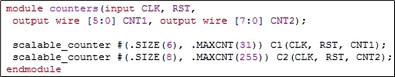
In this example, both parameters in each instance are overridden. There is no requirement to do so. Thus, the following line would override parameter MAXCNT only, leaving the size at the default value of four bits.

Figure 4.10 uses “named parameter redefinition,” a feature added to Verilog in the 2001 revision to the language standard. Earlier ways of overriding parameter values remain available.
One of such method is “parameter value assignment.” It does not explicitly say which parameter is being overridden but otherwise looks similar to named parameter redefinition. The design of Figure 4.10 is rewritten in Figure 4.11 to use this older method.

Besides the obvious lack of name association with each parameter, this second method has the disadvantage of not being able to skip a leading parameter. If only MAXCNT needs to be changed in an instance of scalable_counter, using value assignments, a value for SIZE would still need to be specified. However, lagging parameters that use the default do not need to be repeated. Thus, the following line would change the size of a counter but leave the terminal value unchanged.

The last method of parameter redefinition is with “defparam.” Unlike the other methods of changing a parameter value, defparam has unlimited scoping. Rather than being limited to operating on instantiations in the current design, defparam can change any parameter in any module anyplace in the design hierarchy.
Use of defparam to change one parameter in one instance is shown in Figure 4.12. When used as shown, defparam works just like the other methods: it changes a parameter in an instance in the current design.

In Figure 4.13, a more dangerous use of defparam is illustrated. Rather than operating on a parameter in a module instantiated in the current design, a parameter in a different module is changed. This parameter, which is in a nonsynthesizable test fixture, is then pushed down to the current design. Because the change is made in a module that is part of the simulation hierarchy but not part of the design hierarchy, simulation/synthesis mismatch is likely.
When designs and design teams were small, allowing such anarchistic changes were a feature of the language, much loved by engineers who chafed under the restrictions of strongly typed languages. With multibillion transistor designs now being implemented in Verilog, the freewheeling nature of defparam is often considered more of a liability, a source of risk, and has gone out of favor.
Another risk associated with defparam is its property of having the last call win. In Figure 4.14, two changes are made to one parameter and none to another, rather than one to each. This is presumably a typographical error, but it is perfectly legal syntax and could result in a defective circuit.

Because hierarchical paths to any parameter from any module are legal, an infinite variety of errors may be introduced maliciously or carelessly through uncontrolled use of defparam. For this reason, its use is banned in many design environments, although it remains supported by current simulation and synthesis tools.
Local parameters
Local parameters, keyword localparam, have the apparently odd property of not being able to have their values changed. While this might seem to defeat the purpose of having them, they do have a use in circuit design. It is to provide mnemonic names for values. Local parameters were added to Verilog in the 2001 language revision and may be unavailable in some older tools.
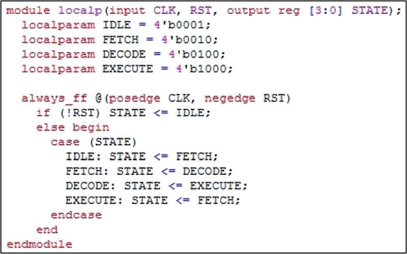
A typical use for local parameters is in state variables. While it would be highly unusual to want to override the value of a state in a state machine, giving meaningful names to states can make a design easier to understand. An example of using local parameters is shown in Figure 4.15. That example makes use of a “case” construct, which is a type of multiway branching. Multiway branching is covered in Chapter 5. The example also uses one-hot encoding. That is not required. As with regular parameters, any value type may be used with localparams.
Enumerated types, covered below, also provide a method of creating meaningful mnemonic names while adding error checking into the variable type, although at the cost of increased complexity and more usage restrictions. Either may be used to give intuitive names to constants. Enumerated types tend to be preferred for complex designs done by large design and verification teams, whereas the simpler local parameters are often preferred for small designs done by an individual or small group.
Enumerated types are a SystemVerilog construct unavailable in standard Verilog.
Specify parameters
Specify parameters, or specparams, are the last of the parameter types. Their use is restricted to specify blocks, which is where performance characteristics for cell models are set. They will be covered in Chapter 11.
Enumerated types
Enumerated types specify a set of values that can be assigned to a variable. Only values specified in the set are legal. Any attempt to assign a value outside of the value set to an enumerated type variable would result in an error. This strong typing represents a complete reversal of the traditional freewheeling assignment rules of standard Verilog, where anything can be assigned to any variable type and mismatched or overflow bits will simply be dropped.
In the following line, enumerated type variable STATE can only be assigned one of three specified values.

Enumerated type variables default to integer size, but no matter how many bits an enumerated type variable is, any assignment of a value other than the ones specified in the declaration would be illegal.
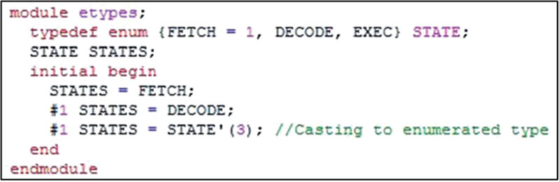
The values in the list do have default values. In the above example, FETCH would be equal to zero, DECODE one, and EXEC two. The default values can be changed with explicit value assignments. In the following line, FETCH is explicitly set to one. With that as a starting point, DECODE will be set to two and EXEC to three.

However, it would still be illegal to directly assign STATE a value of three. Only FETCH, DECODE, and EXEC would work, even though EXEC is equal to three. This is illustrated in Figure 4.16.

Mixing explicit assignments with automatic incrementing of enumerated types can lead to more than one type having the same value. This is illegal and prevents the code containing the duplicate assignment from compiling. An example of this illegal condition is shown below.

In enumerated type LETTERS, both BETA and GAMMA would be two. The code would not compile, as values must be unique.
Unlike the standard Verilog “int” type, SystemVerilog integers are explicitly defined to be 32 bits. While they are legal for synthesis, this sizing frequently makes them undesirable for circuit design. Instead, vectors properly sized for each variable are typically used.
Rather than using the default 32-bit integers, enumerated types can be sized to avoid creating any superfluous hardware. The local parameter example of Figure 4.15 could be rewritten to use an enumerated type as shown in Figure 4.17. Use of a typedef is necessary when changing the enumerated type from the default integer. It has the added benefit of allowing any number of variables of the newly created type to be added. Thus, once the STATES type has been created, the following lines would become legal:


This construct is frequently found in state machines where the combinational next state logic is separated from the state registers. An example of such a state machine is included in Chapter 12.
In Figure 4.17, the STATE variable is four bits wide but only 4 of the possible 16 encodings are enumerated, meaning that only those 4 values may be assigned to it. This restriction is the primary difference between using localparams and enumerated types. With localparams, the anticipated values can be given mnemonic names, but there is no restriction on values that can be assigned to variables. With enumerated types, any attempt to assign a value outside of the specified set will produce an error, which can then be fixed during the verification phase of a design.
This feature may be bypassed via casting. In the event that a designer is absolutely determined to assign a value outside of the enumerated set, that value can be cast as shown in Figure 4.18.
Direct assignment of an enumerated value to a variable as is done in Figure 4.18 will always work, but sometimes optimal circuit design calls for navigating around the values by incrementing and decrementing the current value. Using normal arithmetic operators can cause errors if not all possible values have been enumerated. SystemVerilog includes the methods shown in Table 4.1 to avoid such errors. The last method in the table, “name,” is not useful for circuit design but may be useful in verification.
Table 4.1
SystemVerilog enumerated type methods
| Method Name | Function |
| first | returns first value of enumeration |
| last | returns last value of enumeration |
| next | returns next from current value |
| prev | returns previous from current value |
| num | returns number of elements in type |
| name | returns string representation of current value |
In Figure 4.19, the enumerated type STATE has only three defined values. If, instead of using the “next” method, variable STATES was incremented by adding one to its current value, the first two increments would work, but the third would result in an illegal assignment. This is because when STATES is equal to EXEC, adding one to it would result in a value of three, which is not one of the enumerated types. Methods, by contrast, wrap back to the beginning so FETCH follows EXEC. This incorrect method of incrementing an enumerated type is shown in Figure 4.20. It could work if all possible bit patterns of the enumerated type were to be defined, but using methods is still the preferred technique.

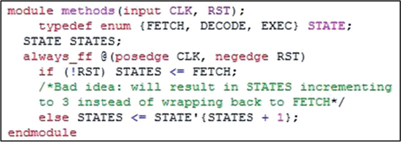
Simply adding one to STATES as shown below would not even compile.

If incrementing or decrementing by one is insufficient, the methods can take an argument to move by any integer value. This is shown in Figure 4.21, where incrementing by two, decrementing by three, going to the first enumerated value, and going to the last enumerated value are all used. Using these methods, only the enumerated values will be used. Incrementing from the last value will go to the first and decrementing from the first will go to the last.

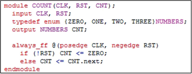
Enumerated types can be ports as well as internal variables. In the example of Figure 4.22, an enumerated type is the output of a counter. When synthesized, the output will be indistinguishable from a two-bit counter created with standard binary operands, but in behavioral simulation the output values will be ZERO, ONE, TWO, and THREE rather than binary values.
The enumerated type is then used as the input to a decoder in Figure 4.23. The input is declared to be a variable of type NUMBERS rather than a two-bit vector.
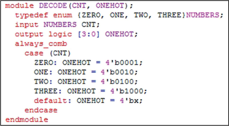
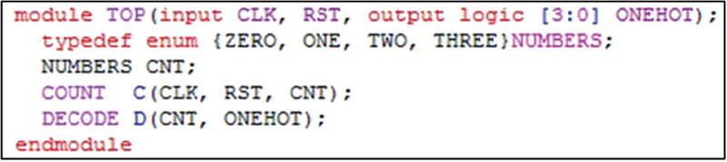
At the top, the enumerated type is passed between the modules. The variable CNT is again of type NUMBERS. It is an input to module DECODE and an output from module COUNT. At the top level of the design, it is a signal that needs to be declared. Otherwise, variable CNT would default to a single-bit wire, which would be incompatible with the signals in the two modules.
A test fixture for the design hierarchy of Figures 4.22–4.24 is shown in Figure 4.25. The enumerated type signal only goes between modules and is not a primary input or output, so it does not need to be declared in the test fixture. A simulation of the system including the internal variable CNT is shown in Figure 4.26.


The test bench uses SystemVerilog variable types bit and logic. Since bit variables default to zeros, the clock signal does not need to be initialized before setting it to toggle every time unit. This feature would present some risk if used in a circuit description, as the actual value at power up may be different. This risk factor only applies to synthesizable modules, not test fixtures. The reset signal is initialized to logic one at time zero, overriding the default assignment of logic zero.
The logic variable ONEHOT could equally well be declared to be a standard Verilog multibit wire. The result would be the same.
To avoid declaring the enumerated type in each module, it could be created in a package. The package would then have to be imported into each module. Packages are discussed later in this chapter. Using a package is preferable to declaring the same type in multiple modules, as then the type only needs to be maintained in one place.
Constants
Constants can be declared with the SystemVerilog keyword “const.” While useful in verification suites, they are so far not useful for synthesis as they may only be assigned a value at initialization. Since initial value assignments are ignored for synthesis, the synthesized hardware ends up with constants that do not have any specific value. In simulation, const declarations are assigned their values at the start of run time, rather than at elaboration like parameters and localparams, which can account for the difficulty in implementing this construct in the synthesizable subset of SystemVerilog. For circuit descriptions, parameters and localparams are used to establish constant values.
Values are declared to be constants in conjunction with another declaration that defines their type. A few examples of constant declarations are shown below.
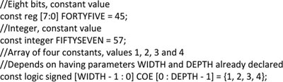
For verification modules and other nonsynthesizable code, constants are a convenient way to give meaningful names to numbers. Since their values are lost in synthesis, they should never be used in circuit description code. Parameters, localparams, and enumerated types may all be used in circuit descriptions.
Packages
SystemVerilog allows declarations to be shared across a design hierarchy by use of packages. While much of the same effect can be accomplished through `ifdef and `include directives, packages provide a more elegant and comprehensive solution.
Packages can include localparams, enumerated types, constants, and subroutine definitions. Packages can import statements from other packages and export them to other packages.
While parameters also can be included in packages, a parameter in a package cannot be redefined, which defeats the purpose of having a parameter. In a package, parameters and localparams work identically. This is so because packages are not local to any instance; thus, redefining a parameter on an instance-by-instance basis is not possible when the parameter is in a package.
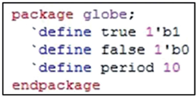
To reference a component of a package, a new SystemVerilog operator, the scope resolution operator, is used. Its symbol is the double colon, “::.” Wildcards may be used with the scope resolution operator to reference multiple components or all components. The definitions file of Figure 4.5 is reworked as a package in Figure 4.27. The package can then be imported into a module compiled with the package and elements of the package referenced as if they were declared locally, as shown in Figure 4.28. In this example, all elements of package globe are imported and then may be used in the module.

In principle, individual elements of the package may be imported. However, doing so presents a problem when those elements are defined macros. In the example of Figure 4.22, if discrete elements were imported rather than the entire package, the macro substitution would take place in the import line itself. Thus, the line
would be interpreted as “import 1'b1;,” which would be a syntax error. The macro `true would remain undefined in the importing module.
Changing the define macros to parameter or localparam declarations avoids this problem. An example of this is shown in Figure 4.29. After they are imported, true and false may be used throughout the module as if they had been declared locally, although they cannot be redefined.

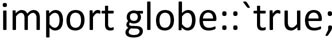
Package elements can also be directly referenced without explicit importation. Thus, the following lines creating a clock generator could be used in a test fixture as long as the package is compiled along with the module.
Using this style, period must be referenced with the package name and scope resolution operator every time it is used.
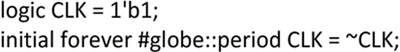
The hierarchical example of Figures 4.22–4.24 is shown in Figure 4.30 reworked to use a package. It would work with the same test fixture shown in Figure 4.25, producing an identical output to that shown in Figure 4.26.
In Figure 4.30, the wildcard operator is used to import all the contents of the package. This technique is efficient, as each of the enumerated types would otherwise need to be individually imported. Replacing the import line with

would be insufficient because the types of type NUMBERS would remain undefined in the modules. Each reference to ZERO, ONE, TWO, and THREE would then produce an error.
For the code shown in Figure 4.30 to work, the package needs to be compiled before any of the modules that reference it.
Filling a scalable variable with all ones
When a variable’s size is fixed, it is easy to set all its bits to any value. However, if a variable’s size is a parameter, setting all bits to logic one can be tricky. In standard Verilog, it can be done through use of negative numbers, but SystemVerilog has added some new syntax to make it easy and intuitive. The same SystemVerilog syntax can also be used to set all bits to logic zero, X, or Z.
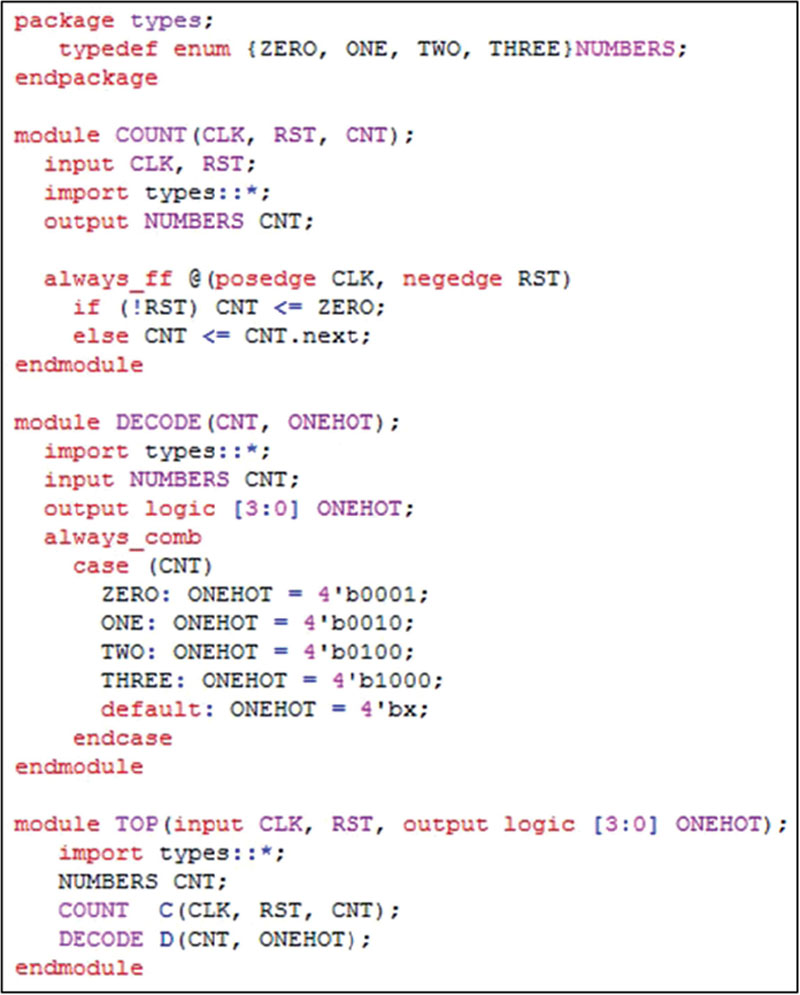
In Figure 4.31, methods for setting all bits of a scalable register are shown [1]. The first three will work in standard Verilog. In the first one, A is set to negative one, which in two’s complement arithmetic means each bit will be set to one. Variable B is set to a bitwise negation of zero, which also results in each bit being set to logic one. The third method uses the replication operator to generate SIZE bits of logic one. The fourth method is a new SystemVerilog option. It too will result in each bit being set to logic one. Note that this is not the same as setting D to `b1. That would result in only the least significant bit being set with all others equal to zero.
To set all bits of D to high impedance or unknown, the following lines would work. Similar syntax could also be used to set all bits to logic zero, but would be unnecessary as simply setting the variable to zero without any size or radix would suffice.

Summary
The techniques presented in this chapter are primarily used to enhance understanding of code through use of mnemonic names. Define macros should be used with a great deal of care, as they can redefine elements of modules anywhere in the design hierarchy. Parameters, localparams, and user-defined types are less susceptible to accidental misuse.
Parameters are a powerful tool for creating flexible, reusable design modules. Their capacity for redefinition on an instance-by-instance basis means that scalable design units may be created and reused repeatedly.
Localparams are only used for mnemonic reference. Their values cannot be changed.
User-defined types share some functionality with localparams but add error checking. Their use is especially appropriate in state machines.
Constants work in simulation but their values are not preserved in synthesis. They should not be used in circuit descriptions.
Packages provide a convenient structure for maintaining and sharing these mnemonic devices throughout a design hierarchy.