
In Chapter 15, we gave several examples of distributed algorithms programmed directly on the “bare” asynchronous network model. As should be apparent by now, this model has so much uncertainty that it is very difficult to program directly. It is, therefore, desirable to have simpler models that can be programmed more easily and whose programs can be translated into programs for the general asynchronous network model.
We have already presented two models that are simpler than the asynchronous network model—the synchronous network model and the asynchronous shared memory model−and have given many examples of algorithms for these two models. In this chapter, we show how algorithms for the synchronous network model can be transformed into algorithms for the asynchronous network model, while in Chapter 17, we show how asynchronous shared memory algorithms can be transformed into asynchronous network algorithms. These transformations enable algorithms for the two simpler models to be run in asynchronous networks.
The idea of transforming synchronous network algorithms into asynchronous algorithms has already been suggested by some of the algorithms that appear in Chapter 15, namely, the simulation of FloodMax using round numbers on all messages in Section 15.2 and the SimpleMST algorithm in Section 15.5.8.
The strategy of transforming synchronous to asynchronous network algorithms works only for non-fault-tolerant algorithms. In fact, such a transformation cannot work for fault-tolerant algorithms because, as we will show in Chapter 21, the capabilities for fault-tolerance are fundamentally different in synchronous and asynchronous networks.
We formulate the transformation from the synchronous network model to the asynchronous network model in terms of a system module called a (local) synchronizer. We then describe several distributed implementations of the synchronizer. All of these implementations involve synchronizing the system at everysynchronous round; this is necessary because the transformations are designed to work for arbitrary synchronous algorithms. The ability to synchronize less frequently (as, for example, in the SimpleMST algorithm) depends on special properties of the algorithm that ensure that it still works correctly if it is allowed to exhibit arbitrary interleavings of process steps between synchronization points.
Our presentation of the synchronizer implementations turns out to be a very good example of modular decomposition of distributed algorithms. We use several algorithm decomposition techniques, most of which are described in Chapter 8. We begin with a “global” specification of correctness in terms of I/O automata. Then we define a local synchronizer abstractly and show that it implements the global specification; this requires techniques based on partial orders of events. Next we describe several alternative ways of implementing the local synchronizer; each could be shown to do so using the simulation method of Section 8.5.5. However, most of these implementations can take advantage of additional decomposition steps. Thus, we define another system module known as a safe synchronizer, show how it can be used to implement the local synchronizer, and then develop several distributed algorithms as implementations of the safe synchronizer. The entire development is a good illustration of the power of decomposition methods in enabling simple description (and proofs) of complicated distributed algorithms.
We close the chapter with a contrasting lower bound on the time overhead required to run a synchronous network algorithm in an asynchronous network, if the synchronization requirements are very strong.
16.1 The Problem
In this section, we describe the problem to be solved by a synchronizer. The starting point is the synchronous network model, with a collection of n synchronous processes running at the nodes of an undirected graph G = (V,E), communicating by messages sent over the edges. In the formulation of that model in Chapter 2, each process i is presented as a kind of state machine, with message-generation and transition functions. Here, we deviate from the earlier development by instead representing each process i as a “user process” I/O automaton Ui. 1
Let M be the fixed message alphabet used in the synchronous system. We define a tagged message to be a pair (m, i) where m ε M and 1 ≤ i ≤ n.
The user automaton Ui has output actions of the form user-send (![]() , r)i, where
, r)i, where ![]() is a set of tagged messages and r
is a set of tagged messages and r ![]() , by which it sends messages to its neighbors. The tag in a tagged message indicates the message destination, and the r argument represents the round number. If Ui does not have any messages to send at round r, then it performs user-send (ϕ, r)i. Ui also has input actions of the form user-receive(T, r)i, where T is a set of tagged messages and r
, by which it sends messages to its neighbors. The tag in a tagged message indicates the message destination, and the r argument represents the round number. If Ui does not have any messages to send at round r, then it performs user-send (ϕ, r)i. Ui also has input actions of the form user-receive(T, r)i, where T is a set of tagged messages and r ![]() , by which it receives messages from its neighbors. Here, a tag indicates the message source and r is again the round number. Ui may also have other external actions by which it interacts with the outside world. We now model inputs and outputs of the user automata using input actions and output actions rather than encoding them in the states (as we did in Chapter 2).
, by which it receives messages from its neighbors. Here, a tag indicates the message source and r is again the round number. Ui may also have other external actions by which it interacts with the outside world. We now model inputs and outputs of the user automata using input actions and output actions rather than encoding them in the states (as we did in Chapter 2).
Example 16.1.1 user-send and user-receive actions
Suppose that n = 4. Then user-send({m1, 1), (m2, 2)}, 3)4 indicates that at round 3, user U4 sends message m1 to user U1 and message m2 to user U2, and sends no other messages. Also, user-receive({(mi, 1), (m,2, 2)}, 3)4 indicates that at round 3, U4 receives message m1 from U1 and message m2 from U2, and receives no other messages.
Ui is expected to preserve the well-formedness condition that the user-sendi and user-receivei actions alternate, starting with a user-sendi action, and that successive pairs of actions occur in order of rounds. That is, the sequence of such actions is a prefix of an infinite sequence of the form
user-send(T1, l)i, user-receive(T’1, l)i, user-send (T2, 2)i, user-receivei(T’, 2)i, user-send(T3, 3),….
There is one other condition—a liveness condition—that Ui is required to satisfy: in any well-formed fair execution, Ui must eventually perform a user-sendi for each round r such that user-receivei events for all previous rounds have already occurred. That is, the users continue sending messages for infinitely many rounds, as long as the system keeps responding.
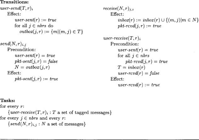
We describe the rest of the system as a global synchronizer, GlobSynch. Its job is, at each round, to collect all the messages that are sent by user automata at that round in user-send actions and to deliver them to all the user automata in user-receive actions. It synchronizes globally, after all the user-send events and before all the user-receive events of each round. See Figure 16.1 for a picture of the combination of user and GlobSynch automata, that is, the GlobSynch system. Notice that user-send actions are input actions of GlobSynch, while user-receive actions are output actions of GlobSynch.

GlobSynch can easily be described as an I/O automaton.

In this code, tray(i, r) is designed to hold the messages to Ui that are submitted by all its neighbors; these messages are tagged with their senders– indices. The user-sent and user-rcvd components just keep track of whether user-send and user-receive events have occurred.
It should not be hard to see that any algorithm in the synchronous network model of Chapter 2 can be described in this new style—as a composition of user automata Ui and the GlobSynch automaton. We leave this for an exercise.
The synchronizer problem is to “implement” the GlobSynch automaton with an asynchronous network algorithm, with one process Pi at each node i of the underlying graph G and a reliable FIFO send/receive channel Ci,j in each direction on each edge (i, j) of G. This implementation should ensure that the individual user automata Ui cannot tell the difference between running in the implementation system (i.e., user automata plus the distributed algorithm) and running in the GlobSynch system. That is, we want to ensure that if alpha is any fair execution of the implementation system, then there is a fair execution α′ of the specification system such that for each i, α is indistinguishable from α′ to Ui.2
Note that we do not require that the relative order of events at different users be preserved, but only the view of each individual user. We will return to this issue in Section 16.6.
16.2 The Local Synchronizer
All of the synchronizer implementations we describe are “local,” in the sense that they only involve synchronization among neighbors in the network rather than among arbitrary nodes. The advantage of using only local synchronization is the potential for savings in communication and time complexity. In this section, we define a local variant of GlobSynch that we call LocSynch; the algorithms will be presented as implementations of LocSynch.
LocSynch is nearly identical to GlobSynch. The only difference is in the user-receive transitions, which are now described by

Thus, in LocSynch, round r messages can be sent to Ui as soon as round r messages have been received from all its neighbors and from Ui itself; it is not necessary to wait for messages from all users in the entire network.
Lemma 16.1 If α is any fair execution of the LocSynch system (i.e., users plus LocSynch), then there is a fair execution α′ of the GlobSynch system that is indistinguishable from α to each Ui.
We cannot use simulation techniques to prove this correspondence as we did, for example, in the proof of TicketME in Section 10.9. This is because the relative order of external actions that happen at different nodes is sometimes different in the two systems. Rather, we use a method based on partial orders of events.
Proof Sketch.Let L and G denote the LocSynch and GlobSynch systems, respectively, modified slightly by reclassifying all the internal actions of the user automata as outputs. (Thus, the external actions of each system are exactly all the actions of the user automata.) Certain events of L “depend on” other events: a user-receive event depends on user-send events for the same round at the same or neighboring nodes, and any event at a user automaton may depend on any preceding event at the same automaton. If β is any trace of L, then we define an irreflexive partial order →β on the events of β as follows. (This is similar to the dependency relations defined in Sections 14.1.4 and 14.2.4.) If π and ϕ are two events in β, with π preceding ϕ then we say that π → β ϕ, or ϕ depends on π, provided that one of the following holds:
- π and ϕ are events of the same user Ui.
- π = user-send(T, r)i and ϕ = user-receive(T’, r)j, where j ε nbrsi.
- π and ϕ are related by a chain of relationships of types 1 and 2.
The key property of these relations is the following claim. It says that the →β beta relations capture enough about the dependencies in the fair trace β to ensure that any reordering that preserves these dependencies is still a fair trace. (This claim is similar to Theorems 14.1 and 14.3.)
Claim 16.2 If β is a fair trace of L and γ is a sequence obtained by reordering the events in β while preserving the →β ordering, then γ is also a fair trace of L.
Given Claim 16.2, to prove the lemma, we start with any fair execution α of L and let β = trace(α). We reorder the events of β to get a new trace γ in which the rounds “line up” globally: we do this by explicitly putting all the user-send events for a particular round r before all the user-receive events for the same round r. This new ordering requirement is consistent with the dependency requirements in the →β since they never require the reverse order, even when they are applied transitively. By Claim 16.2, γ is also a fair trace of L. But, in addition, since all the user-send events for each round r precede all the user-receive events for the same round r, it is not hard to show that γ is a trace of G. To complete the proof, we fill in the states in γ to get an execution of G, filling in the user states as in α Formally, this filling in can be done using general theorems about I/O automaton composition, in particular, Theorems 8.4 and 8.5.
A simple example of a distributed algorithm that implements LocSynch is as follows.
SimpleSynch algorithm (informal):
For any round r, after receiving an input of the form user-send(T, r)i, process SimpleSynchi first sends a message to each neighbor SimpleSynchj, containing the round number r and any messages from Ui to Uj that appear in T. When SimpleSynchi has received a round r message from each of its neighbors, it outputs user-receive(T’, r)i, where T’ is the set of messages received, each tagged with its sender.
More formally, SimpleSynchi is the following automaton.


The SimpleSynch system is obtained by composing the SimpleSynchi processes, reliable FIFO send/receive channels Cjj for all the edges, and the users. See Figure 16.2.
Lemma 16.3 If α is any fair execution of the SimpleSynch system, then there is a fair execution ά of the LocSynch system that is indistinguishable from α to each Ui.
Proof Sketch.This time, unlike in the proof of Lemma 16.1, there is no reordering of events at different users, and the correspondence can be proved using simulation methods. Let S and L denote the SimpleSynch and LocSynch systems, respectively, each modified slightly so that the actions that are classified as external are exactly all the actions of the user automata. (That is, the internal actions of the users are reclassified as outputs and the send and receive actions are “hidden”—reclassified as internal.) If s and u are states of S and L, respectively, then we define (s, u) ε f exactly if all of the following hold:
- All user states are identical in s and u.
- u. user-sent(i, r) = s. user-sent(r)i
- . u.user-rcvd(i, r) = s. user-rcvd(r)i
- u. tray(i, r) = Uj≠i{(m, j) : m ε s. outbox(i, r)j}
To prove that f is a simulation relation, we need the following invariant assertion for S.
Assertion 16.2.1 In any reachable state of the SimpleSynch system, if pkt-rcvd(j, r)i = true, then
- user-sent(r)j = true
- m : (m, j) ε inbox (r)i} = outbox(i, r)j
The proof of this invariant uses other intermediate invariants, involving the correctness of the messages in transit. (As before, we assume that the channels are universal reliable FIFO channels in the statement and proof of such invariants.) Given Assertion 16.2.1, the proof that f is a simulation relation is straightforward; the only interesting case is user-receive, which uses Assertion 16.2.1 in its proof. We leave the details of the invariant and simulation proofs as an exercise.
The existence of a simulation relation implies that every trace of S is a trace of L. (Recall that the actions that are included in these traces are exactly the actions of the user automata.) But we need more—in particular, we need to know that the fairness conditions of S imply the fairness conditions of L. We prove that fairtraces(S) ![]() fairtraces(L), then apply general composition theorems about I/O automata (Theorems 8.4 and 8.5) to fill in the user states and obtain the needed relationship between executions.
fairtraces(L), then apply general composition theorems about I/O automata (Theorems 8.4 and 8.5) to fill in the user states and obtain the needed relationship between executions.
To prove fair trace inclusion, we use the fact that a simulation relation guarantees more than just trace inclusion—it also guarantees a close correspondence between executions, as defined in Section 8.5.5. Let β ε fairtraces(S) and let α be any fair execution of S with β = trace(α). Then Theorem 8.13 implies that there is an execution α′ of L that corresponds to α, with respect to alpha. We claim that α′ is a fair execution of L.
There are two ways in which it might fail to be fair. First, there might be some user task that is enabled from some point on in α′ yet no step of that task occurs after that point in α′ Then the correspondence implies that the same user task is enabled from some point on in α, but no step of that task occurs; this is a contradiction to the fairness of α with respect to that user task.
Second, there might be some i and r such that the user-receivei task for round r is enabled from some point on in α′ yet no step of that task occurs. This implies that, from the given point on in α′ user-sent(j, r) = true for all j ε nbrsi U{i}, and user-rcvd(i, r) = false. The correspondence then implies that from the corresponding point in α, user-sent(r)j = true for all j ε nbrsi cup {i}, and user-rcvd(r)i = false.
We use the following assertion.
Assertion 16.2.2In any reachable state of the SimpleSynch system, the following holds. If pkt-sent(i, r)j = true, then either channel Cj,i contains a message or pkt-rcvd(j, r)i = true.
Then for each j ε nbrsi, fairness for the send task at round r implies that eventually in α, pkt-sent(j, r)i becomes true. Then Assertion 16.2.2 and channel fairness imply that eventually pkt-rcvd(j, r)i becomes true. Then fairness for the user-receivei task at round r in S implies that a step of this task eventually occurs in α, and so, by the correspondence, in α′, a contradiction.
Note that the proof of Lemma 16.3 actually shows that fairtraces(S) ![]() fairtraces(L), in addition to showing indistinguishability to the individual users. Lemmas 16.1 and 16.3 imply
fairtraces(L), in addition to showing indistinguishability to the individual users. Lemmas 16.1 and 16.3 imply
Theorem 16.4 If α is any fair execution of the SimpleSynch system, then there is a fair execution α′ of the GlobSynch system that is indistinguishable from α to each Ui.
Complexity analysis. Each round requires 2|E| messages, one in each direction on each edge of the graph. Suppose that c is an upper bound on the time for any user-sendi event to occur, once all user-receivei events for any smaller rounds have occurred; that ℓ is an upper bound on the time for any task of any process; and that d is an upper bound on the time for delivering the oldest message in any channel. Then the total amount of time required to simulate r rounds is at most r(c + d + O ((ℓ)).
16.3 The Safe Synchronizer
It is impossible to reduce the time complexity of the SimpleSynch algorithm significantly, but it is possible to reduce the communication complexity. Namely, if there is no message from Ui to neighbor Uj at round r in the underlying synchronous algorithm, then we may be able to avoid a round r message from process i to process j in the asynchronous algorithm. But we cannot simply omit these messages. Each process needs to determine that it has already received all the messages that its neighbors will ever send it for round r, before it can perform a user-receive output for round r. The messages of the SimpleSynch algorithm are used to help determine this, as well as to deliver the user’s messages. The basic strategy for reducing communication is to separate these two functions.
Thus, we decompose the implementation of LocSynch into several pieces: a “front end,” FrontEnd for each node, communicating with the FrontEnds of neighboring nodes over special channels Di,j, and a “safe synchronizer,” Safe-Synch. See Figure 16.3 for this new architecture. The job of each FrontEndi is to deliver the messages received from the local user Ui in user-sendi events. At each particular round r, after receiving a user-sendi, FrontEndi sorts all the outgoing messages for round r into “outboxes.” Then it sends the contents of each nonempty outbox to the appropriate neighbor j using channel Di,j and waits to receive an acknowledgment on Dj,i. When FrontEndi has received acknowledgments for all of its messages, it is said to be safe; this implies that all of i’s messages have been received by the appropriate neighboring FrontEnds. Meanwhile, FrontEndi collects and acknowledges messages sent to it by its neighboring FrontEnds.
When is it permissible for FrontEndi to perform a user-receivei for round r, that is, to deliver to Ui all the round r messages it has collected from its neighbors? It can only do this when it knows that it already has received all the messages it will ever receive for round r. It is therefore sufficient for FrontEndi to determine that all its neighboring FrontEnds are safe for round r, that is, that those neighbors know that all their messages for round r have been received by the appropriate FrontEnd automata.
Thus, the job of the safe synchronizer automaton SafeSynch is to tell each FrontEnd automaton when all its neighbors are safe. To do this, SafeSynch has ok input actions, outputs of the FrontEnd automata, by which the FrontEnd automata tell SafeSynch that they are safe. SafeSynch sends goi to FrontEndi when it has received an ok from each of i’s neighbors, as well as from i itself.
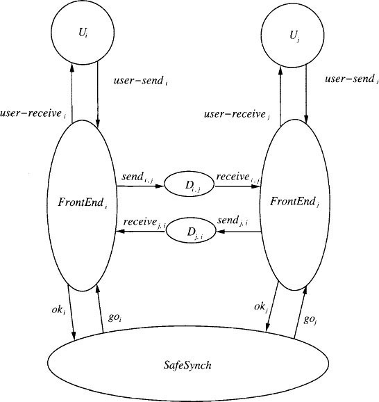
After FrontEndi receives goi, it can perform a user-receivei. In the rest of this section, we describe this decomposition in more detail.
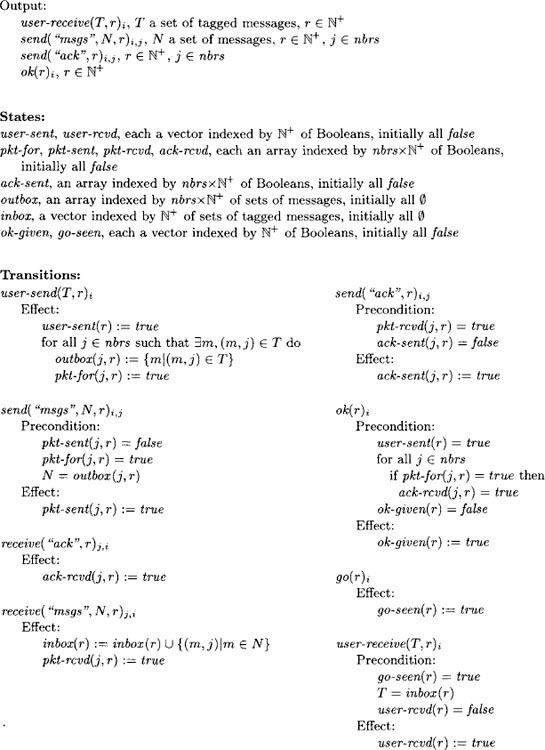
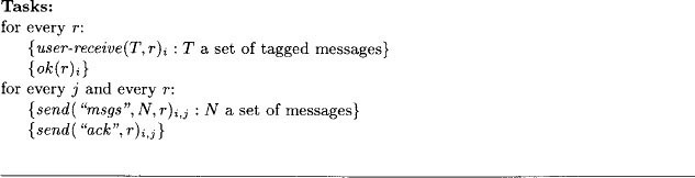
16.3.1 Front-End Automata

16.3.2 Channel Automata
Each pair of front end automata, FrontEndi and FrontEndj, communicate by means of two channel automata, Di,j and Dj,i. These are reliable send/receive channels from i to j and from j to i respectively, as defined in Section 14.1.2.
16.3.3 The Safe Synchronizer
The entire job of the safe synchronizer, SafeSynch, is to wait until it has received oks from all of the neighbors of FrontEndi and from FrontEndi itself before performing goi.

16.3.4 Correctness
Lemma 16.5 If α is any fair execution of the SafeSynch system, (i.e., Front-End, channel, SafeSynch, and user automata, as depicted in Figure 16.3), then there is a fair execution α′ of the LocSynch system that is indistinguishable from a to each Ui.
Proof Sketch. This is proved using a simulation relation from the SafeSynch system to the LocSynch system. The strategy is the same as the one used in the proof of Lemma 16.3 for the SimpleSynch algorithm, using exactly the same simulation relation f, but the details are a little more complicated here because the algorithm is more complicated. Again, the only interesting case in the simulation proof is the user-receive action, which here requires this invariant assertion.
Assertion 16.3.1 In all reachable states of the SafeSynch system, the following holds. If go-seen(r)i = true, then for all j ε nbrsi,
- user-sent(r)j = true
- {m : (m, j) ε inbox(r)i} = outbox(i, r)j.
This assertion in turn needs some auxiliary invariants for its proof, for example,
Assertion 16.3.2 In all reachable states of the SafeSynch system, the following holds. If ok-seen(j, r) = true, then3
- user-sent(r)j = true
- {m : (m, j) ε inbox(r)i} = outbox(i, r)j for all i ε nbrsj
Further details are left to the reader.
Now Lemmas 16.1 and 16.5 imply
Lemma 16.6 If α is any fair execution of the SafeSynch system, then there is a fair execution α′ of the GlobSynch system that is indistinguishable from α to each Ui.
It still remains to implement the SafeSynch automaton with a distributed algorithm. We describe several ways of doing this in the following section. It is also necessary to implement the Di,j channels using the actual send/receive channels Ci,j. This is done by “multiplexing” the Ci,j. so that they implement not only the channels of the distributed implementation of SafeSynch but the Ci,j.’s as well. The multiplexing strategy is described in Exercise 14.6.
16.4 Safe Synchronizer Implementations
In this section, we describe several implementations of SafeSynch by distributed algorithms. There are two main implementations, Alpha and Beta, plus a way of combining them to obtain a hybrid implementation Gamma.
Recall that the job of SafeSynch is, for each round and each i, to wait until it has received oks from all of the neighbors of FrontEni and from FrontEni itself, and then to perform goi.
16.4.1 Synchronizer Alpha
The most straightforward implementation of SafeSynch is the Alpha synchronizer, which works as follows.
Alpha synchronizer:
When any process Alphai receives an oki for any round r, it sends this information to all of its neighbors. When Alphai has heard that all its neighbors have received oks for round r and Alphai itself has also received an ok for round r, then Alphai outputs goi.
We leave to the reader the task of writing the precondition-effect code for each Alphai the structure of the code is somewhat similar to that of SimpleSynchi. Correctness—both safety and liveness—is easy to show, using simulation techniques to relate the Alpha system (Alphai, FrontEnd, Di,j, and user automata) to the SafeSynch system.4 We obtain
Theorem 16.7 If α is any fair execution of the Alpha system, then there is a fair execution α′ of the GlobSynch system that is indistinguishable from α to each Ui.
Complexity analysis.We analyze the complexity of the entire Alpha system. The communication complexity depends on the number of messages sent by the underlying synchronous algorithm: if the synchronous algorithm sends a total of m non-null messages in r rounds, then the Alpha system sends a total of at most 2m + 2r|E| messages to simulate r rounds. The 2m is for the msgs and ack messages sent by the FrontEnds, while the 2r|E| term is for the messages sent within Alpha itself. This term accounts for a message in each direction on each edge at each round.
If c, ℓ, and d are defined as for the SimpleSynch algorithm, then the total amount of time required to simulate r rounds is at most r(c + 3d + O (ℓ)). (This does take pileups in the underlying channels into account.) Thus, both the communication complexity and the time complexity of Alpha are worse than the corresponding costs for SimpleSynch.
Like SimpleSynch, Alpha has a reasonable time complexity but high communication complexity. In the following subsection, we give an alternative implementation of SafeSynch that has better communication complexity but at the cost of additional time complexity.
16.4.2 Synchronizer Beta
Synchronizer Beta assumes the existence of a rooted spanning tree of the entire graph G, preferably one of small height.
Beta synchronizer:
At round r, all processes convergecast all their ok information to the root, along the edges of the spanning tree. After the root has collected this information from all the processes, it broadcasts permission to perform go outputs, also along the edges of the spanning tree.
Again, we leave to the reader the task of writing the precondition-effect code for each process Betai of Beta. The ideas are similar to those used for broadcast and convergecast in Section 15.3. Again, correctness is easy to show, using simulation techniques to relate the Beta system to the SafeSynch system.
Theorem 16.8 If α is any fair execution of the Beta system (Betai, FrontEnd, Di,j, and user automata), then there is a fair execution α′ of the GlobSynch system that is indistinguishable from α to each Ui.
Complexity analysis.If the underlying synchronous algorithm sends a total of m non-null messages in r rounds, then the Beta system sends a total of at most 2m + 2rn messages to simulate r rounds. The 2m is as for Alpha, while the 2rn is for the broadcast and convergecast messages. If h is an upper bound on the height of the spanning tree, then the total amount of time to simulate r rounds is at most r(c + 2d + O (ℓ) + 2h(d + O (ℓ))), or r(c + O (hd) + O (hℓ)).
16.4.3 Synchronizer Gamma
By combining the ideas of synchronizers Alpha and Beta, we can get a hybrid algorithm, Gamma, that (depending on the structure of the graph G) can simultaneously do as well as Alpha in terms of time and as well as Beta in terms of communication.
Algorithm Gamma assumes a spanning forest of G, where each tree in the forest is rooted. We call each tree a cluster, for each cluster C, we write nodes(C) for its set of nodes. (Constructing a suitable spanning forest is itself an interesting problem, but we do not describe how to do this here.) Gamma uses a version of Beta to synchronize the nodes within each cluster and a version of Alpha to synchronize among clusters.
In the extreme case where each cluster consists of a single node, Gamma is the same as Alpha, whereas in the case where there is only a single cluster containing all the nodes, Gamma is the same as Beta. For intermediate cases, both the communication and time complexity measures of Gamma are intermediate between those of Alpha and Beta.
Example 16.4.1 Cluster decomposition
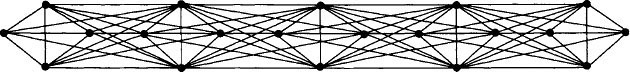
Consider a network graph G consisting of p complete graphs, each with k nodes. The complete graphs are arranged in a line, with all the nodes of adjacent pairs of complete graphs connected to each other. See Figure 16.4 for the case where p = 5 and k = 4. (In the diagram, some edges are not visible because they are “under” other edges.) Now consider the cluster decomposition for G depicted in Figure 16.5.

Each cluster C of this decomposition is a tree for one of the k-node complete graphs in G. The root for each cluster tree is the nodeat the top. Algorithm Gamma uses a version of Beta to synchronize within each of the k-node trees, and a version of Alpha to synchronize among the p trees.
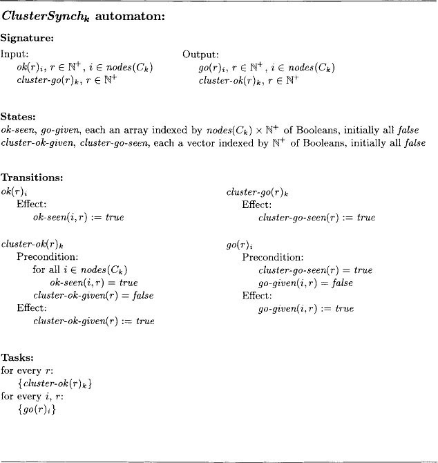
Since Gamma is a combination of two algorithms, we begin with a high-level decomposition of SafeSynch into two kinds of automata, which we call ClusterSynch and ForestSynch automata. There is a ClusterSynchk. automaton for each cluster Ck, and a single ForestSynch automaton. See Figure 16.6 for the architecture.
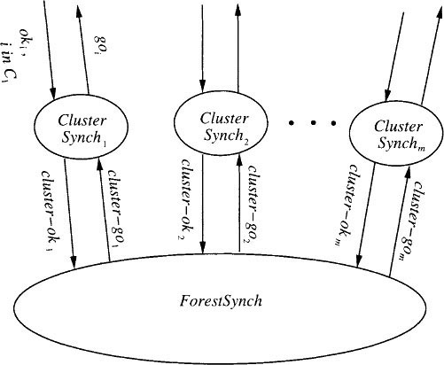
For each cluster Ck and any round r, the automaton ClusterSynchk has two jobs. First, after it receives oki inputs for all nodes i in Ck, it outputs a single cluster-okk to ForestSynch. And second (in a completely independent task), after a cluster-gok input arrives from ForestSynch, ClusterSynchk produces a goi for each node i in Ck- This combination of jobs is a lot like the activities of Beta. Written as an abstract automaton:
The ForestSynch automaton is (up to renaming of external actions) a safe synchronizer for the cluster graph G′ of G, where the nodes of G′ correspond to the clusters of G, and there is an edge in G′ from Ck to Cℓ exactly if there is an edge in G from some node in Ck to some node in Cℓ. Define the ClusterForest system to consist of the ClusterSynch, ForestSynch, FrontEnd, Di,j, and user automata.
Lemma 16.9If α is any fair execution of the ClusterForest system, then there is a fair execution α′ of the SafeSynch system that is indistinguishable from α to each Ui.
Proof Sketch.A simulation proof can be used, but, for variety, we sketch an operational argument, based on executions. The main thing that needs to be shown is that if go(r)i occurs, then previously ok(r)j must have occurred, for each j ε nbrsi U {i}. There are two cases.
- i and j are in the same cluster Ck (possibly with i = j).
Then the code for ClusterSynchk implies that prior to the go(r)i, there must be a cluster-go(r)k Then the definition of ForestSynch implies that prior to the cluster-go(r)k, there must be a cluster-ok(r)k But this in turn implies that there is a previous ok(r)j, which suffices. - i is in cluster Ck, and j is in cluster Cℓ, k ≠ ℓ.
Since j ε nbrsi, it must be that the two clusters Ck and Cℓ are neighbors in the cluster graph G′ (by definition of neighboring clusters in the cluster graph). As before, prior to the go(r)i, there must be a cluster-go(r)k Then the definition of ForestSynch implies that, prior to this, there must be a cluster-okℓ. This implies as before that there is a previous ok(r)j.
To finish the description of synchronizer Gamma, we describe how to implement the ForestSynch and ClusterSynch automata with distributed algorithms. ClusterSynchk can be implemented using a variant of synchronizer Beta on the rooted tree Ck That is, a convergecast is first carried out, collecting the oks at the root, which then performs a cluster-ok output. The root also receives cluster-go, then broadcasts to all the nodes in nodes(Ck) to tell them to perform go. (These two activities could actually be formalized using two separate automata.)
Any implementation of SafeSynch may, with suitable renaming, be used to implement ForestSynch; we choose synchronizer Alpha. A technical complication is that we cannot run Alpha directly on the given distributed network, because Alpha is supposed to run on processes that correspond to the entities being synchronized (which in this case are whole clusters), using channels that correspond to edges between neighboring entities (here, clusters). The given model only allows processes and channels corresponding to the nodes and edges of G. However, it is not hard to implement the needed processes and channels: we run the process for any cluster at the cluster’s root node and simulate direct communication between processes for neighboring clusters using a designated path between the root nodes in the two clusters. Such a path must exist, because the clusters are connected and there exist nodes in the two clusters that are neighbors in G. Again, some preprocessing is needed to determine these paths, but we ignore this issue here. The cluster-ok and cluster-go actions are implemented as internal actions of the processes at the root nodes of the clusters.
Example 16.4.2 Implementing Alpha
Consider the network graph G and cluster decomposition of Example 16.4.1. For that graph and decomposition, we run the Alpha process for each cluster at the root (the top node, in Figure 16.5) of that cluster’s tree. Communication between the Alpha processes for neighboring clusters could be simulated using the direct edge in the underlying graph G (in Figure 16.4) between the roots of the clusters.
In the complete implementation Gamma, the process associated with each node i of G is, formally, a composition of three processes: FrontEnai, process i in the ClusterSynch implementation, and process i in the ForestSynch implementation. Each channel Ci,j is used to implement three channels: Di,j and the channels from i to j in the ClusterSynch and ForestSynch implementations. Defining the Gamma system to be the entire implementation, we can use simulation techniques to prove the following.
Theorem 16.10 If α is any fair execution of the Gamma system, then there is a fair execution α′ of the GlobSynch system that is indistinguishable from α to each Ui.
Orthogonal decompositions.You may find it interesting to observe that the complete Gamma system has two natural decompositions. One is logical, in terms of the functions (data communication, cluster synchronization, and forest synchronization) being performed. The other is spatial, in terms of processes and channels in the complete implementation. These two decompositions correspond to different orders of composing the primitive I/O automata that constitute the algorithm. Since the composition operation is associative, we end up with the same algorithm either way we look at it.
Complexity analysis.Let h be the maximum height of any cluster tree and let α′ be the total number of edges on all the paths used for communication among the roots. If the underlying synchronous algorithm sends a total of m non-null messages in r rounds, then the Gamma system sends a total of at most 2m + O (r(n + α′)) messages. The O (rn) is for the messages sent within all the cluster trees in the ClusterSynch implementation. The O (rn) is for the messages sent between roots in the ForestSynch implementation. The time required to simulate r rounds is ![]() then Gammauses fewer messages than Alpha, and if the maximum height of a cluster spanning tree is much less than the height of a spanning tree of the entire network, then Gamma takes less time than Beta.
then Gammauses fewer messages than Alpha, and if the maximum height of a cluster spanning tree is much less than the height of a spanning tree of the entire network, then Gamma takes less time than Beta.
Example 16.4.3 Comparative complexity of Alpha, Beta, and Gamma
Again consider the network graph G and cluster decomposition of Example 16.4.1. For that graph and decomposition, we compare the costs of the three safe synchronizer implementations we have given. Costs are per round, and we neglect the costs incurred by the users, FrontEnds, and Di,j’s, which are the same for all three algorithms; we also neglect local processing time. For Beta, we assume that the tree used has the minimum possible height, approximately p.
| Messages | Time | |
| Alpha: | 0 (pk2) | 0 (d) |
| Beta: | 0 (pk) | 0 (pd) |
| Gamma: | O(pk) | O(d) |
If p and k are approximately equal, then Gamma represents an order-of-magnitude improvement over each of Alpha and Beta.
16.5 Applications
The synchronizer algorithms given in the previous sections allow a fault-free asynchronous network to implement any non-fault-tolerant synchronous network algorithm. (The synchronizers do not work for fault-tolerant algorithms such as those in Chapter 6.) In this section, we give a few examples of asynchronous algorithms constructed using synchronizers.
Recall that we are considering only undirected networks in this chapter. In all the analyses in this section, we neglect local process step times.
16.5.1 Leader Election
Using synchronizers, synchronous ring leader-election algorithms such as LCR and HS can be run in an asynchronous ring. But this is not interesting, because these algorithms already work in an asynchronous network, without the overhead introduced by synchronizers.
In an asynchronous network based on an arbitrary undirected graph with a known diameter, diam, a synchronizer can be used to run the FloodMax synchronous leader-election algorithm. Using synchronizer Alpha, the resulting algorithm sends O (|E|∙diam) messages and takes O (diam.d) time to simulate the necessary diam synchronous rounds.
A synchronizer can also be used to run the OptFloodMax synchronous leader-election algorithm, which is like FloodMax except that nodes only send messages when they have new information to send. If synchronizer Alpha is used, the advantage of the optimization is lost, since the synchronizer itself sends messages on all channels at all rounds. However, if synchronizer Beta is used, then communication complexity is kept reasonably low (at the cost of additional time).
16.5.2 Breadth-First Search
Recall that the SynchBFS algorithm in Section 4.2 requires O (|E|) messages and O (diam) rounds in a network with diameter diam; the processes are not required to know diam. Using synchronizers, the SynchBFS algorithm can be run in an asynchronous network. With synchronizer Alpha, the resulting algorithm sends O (|E|∙diam) messages and requires O (diam∙d) time to simulate the diam rounds needed for all processes to output their parent information. With Beta (using a tree of height at most diam), the algorithm sends only O (|E| + n ∙ diam) messages and takes O (diam2 ∙ d) time, which is the same as the LayeredBFS algorithm given in Section 15.4. Some improvement in the time complexity is possible using Gamma, at the expense of extra communication complexity.
There is a technicality: it is not obvious how the BFS algorithms obtained using the synchronizers are supposed to terminate. As described, the implementation continues to simulate rounds forever, thus generating an infinite number of messages. (If the processes knew diam, then they could simply stop after simulating diam rounds, but we have assumed here that the processes do not know diam.) An ad hoc solution to this problem is to have each user automaton that determines its parent perform only one additional round to notify its neighbors and then halt.
16.5.3 Shortest Paths
For the problem of finding shortest paths from a designated source, the use of a synchronizer is a big win. Recall that the AsynchBellmanFord algorithm has both message and time complexities that are exponential in the number of nodes. However, the synchronous BellmanFord algorithm has communicationcomplexity “only” O (n|E|) and round complexity only O (n), for a network with known size n. We can run the synchronous BellmanFord algorithm using, say, synchronizer Alpha, obtaining an algorithm that sends O (n|E|) messages and uses O (nd) time to simulate the required n rounds. Synchronizer SimpleSynch would work just as well.
16.5.4 Broadcast and Acknowledgment
It is possible to design a synchronous algorithm that allows a process to broadcast a message to all other processes and receive an acknowledgment in return and that uses O (|E|) messages and O (diam) rounds (see Exercise 4.8). We can run this algorithm using synchronizer Alpha, thus obtaining an asynchronous algorithm for broadcast and acknowledgment that uses O (|E| ∙ diam) messages and O (diam ∙ d) time. Compare this with the complexity of AsynchBcastAck in Section 15.3.
16.5.5 Maximal Independent Set
Synchronizers can also be used with randomized synchronous algorithms such as LubyMIS. We leave the details for you to work out.
16.6 Lower Bound on Time
An informal paraphrase of the results about synchronizers is as follows:
Any (non-fault-tolerant) synchronous algorithm can be transformed into a corresponding asynchronous algorithm without too great an increase in costs.
In particular, by using synchronizer Alpha or SimpleSynch, it is possible not to increase the time cost at all. In this section, we show a limitation on the synchronizer approach, by giving a lower bound on the time required for an asynchronous network algorithm to solve a particular problem. Since there is a very fast synchronous algorithm to solve the same problem, this means (informally speaking) that
Not every synchronous algorithm can be transformed to a corresponding asynchronous algorithm with a similar time complexity.
These two informal paraphrases appear to be contradictory. It turns out that the reason for the difference is the locality of the correctness condition guaranteed by the synchronizers. We return to this point after the lower bound proof.
The result of this section is the only lower bound in this book for the time complexity of a problem in an asynchronous distributed system.
The problem we consider is called the “session problem.” Let G = (V, E) be a graph, with diam its diameter as usual. The system’s interface with its environment includes flashy output actions, one for each node i of G; flashi is an output of the process automaton at node i. We treat the flashi actions as abstract actions, but you might want to think of them as signals that the corresponding processes have completed some computation task.
Define a session to be any sequence of flash events containing at least one flashi for every i. For any nonnegative integer k, the k-session problem requires simply that the algorithm should perform at least k disjoint sessions, in any fair execution.
Example 16.6.1 Motivation for the k-session problem
The k-session problem was originally inspired by a matrix computation problem for the asynchronous shared memory model. Consider a collection of asynchronous parallel processes performing a coordinated calculation of the transitive closure of an m ![]() m Boolean matrix. The matrix starts out in shared memory, and all the partial results and final outputs are written to shared memory.
m Boolean matrix. The matrix starts out in shared memory, and all the partial results and final outputs are written to shared memory.
There is a process Pi,j,k for every i,j,k,1 ≤ i,j,k ≤ m. Each process Pi,j,k is responsible simply for writing 1 in location (i, j) of the output matrix in case it ever sees Is in both locations (i, k) and (k, j). Thus, each goes through a simple loop, reading locations (i, k) and (k, j), then (possibly) writing (i, j). Each individual read or write operation on shared memory is represented abstractly as a flash output.
Basic properties of matrices then imply that the calculation is performed correctly if there is “enough” interleaving among the process steps. Specifically, O(logn) sessions suffice. It does not matter if the processes do excess reading and writing—as long as enough interleaving occurs, the correct output will be produced.
A simpler version of the problem for which a similar lower bound could be proved is one in which each process is required to perform exactly one flash in each session. The version of the problem that we use is less constrained, so it leads to a stronger lower bound result.
It is trivial to solve the k-session problem in the synchronous network setting. All we need is for each process i to perform a single flashy output at each of k rounds. No communication between processes is required. The number of rounds needed is exactly k.
In the asynchronous network setting, we model the processes as I/O automata as usual, connected by reliable FIFO send/receive channels. Without loss of generality, we assume that the channels are universal. We associate times with events as usual, with ℓ as an upper bound for the time of each process task and d as an upper bound for the delivery time of the oldest message in each channel. We assume that ℓ ![]() d and in fact will ignore ℓ in our result and proof. Recall from Section 8.6 that a fair execution with times associated with all events, subject to the given restrictions, is called a timed execution.
d and in fact will ignore ℓ in our result and proof. Recall from Section 8.6 that a fair execution with times associated with all events, subject to the given restrictions, is called a timed execution.
Next, we define the time measure T(A) for algorithm A. For each timed execution α of A, define T(α) to be the supremum of the times at which a flash event occurs in α. (We use a supremum instead of a maximum here because there could be infinitely many such events.) Then define
T(A) = sup{T(α) : α is a timed execution of A}.
That is, T(A) is the supremum of the times at which a flash occurs in any timed execution of A.
We can now state and prove the lower bound.
Theorem 16.11Suppose A is an asynchronous network algorithm that solves the k-session problem on graph G. Then T(A) ≥ (k – 1) diam. d.
In order to compare this result with the simple upper bound of k rounds for the synchronous setting, it is probably reasonable to charge time d, the maximum message-delivery time, for each round. Then the discrepancy between the inherent lower bound of Theorem 16.11 and the small upper bound of kd is approximately a factor of diam. This proves that the inherent overhead due to asynchrony, for the session problem, is a factor of diam.
Proof. We assume without loss of generality that all actions of A are external. We proceed by contradiction.
Suppose that there exists an algorithm A with T(A) < (k – 1) < diam ∙ d. Define a timed execution of A to be slow if all the message deliveries take the maximum time d. Let α be any slow timed execution of A; note that α with its time information suppressed must be a fair execution of A. Since A is correct, α must contain k sessions. By assumption, no flash event occurs in α at or after time (k–1) ∙ diam ∙ d. So we can write α as a concatenation ![]() where the time of the last event in α′ is strictly less than (k – 1) ∙ diam ∙ d and where there are no flash events in α′. Moreover, we can decompose α” into k – 1 smaller pieces, as a concatenation α1. α2.….αk – 1, where in each of the fragments α, 1 ≤ r ≤ k – 1, the difference between the times associated with the first and last events is strictly less than diam.d.
where the time of the last event in α′ is strictly less than (k – 1) ∙ diam ∙ d and where there are no flash events in α′. Moreover, we can decompose α” into k – 1 smaller pieces, as a concatenation α1. α2.….αk – 1, where in each of the fragments α, 1 ≤ r ≤ k – 1, the difference between the times associated with the first and last events is strictly less than diam.d.
We now construct a fair trace β of A; β will be an ordinary untimed fair trace—without times associated with its events. It is constructed as a concatenation of the form β =β1 ∙ β2∙…βk – 1β′′, where each βr is obtained by reordering the actions in α′ (and removing the times) and β′′ is just the sequence of actions in α” (with the times removed). We will show that β contains fewer than k sessions, which will contradict the correctness of A.
All the reordering that we do in constructing β will preserve the important dependencies among actions in α, in particular, the dependency of a receive event on the corresponding send event and the (possible) dependency of any event of any process i on any prior event of the same process. We use the notation →trace(α), as defined in Section 14.1.4, for the irreflexive partial order that describes these dependencies. Theorem 14.1 will be used to show that β is in fact a fair trace of A.
The following claim describes the properties we require of our reordered sequences βr. Fix jo and j1 to be any two nodes of G whose distance is equal to diam, and define
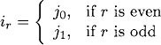
Claim 16.12For every r, 1 ≤ r ≤ k – 1, there exists a sequence βr of actions of A such that the following properties hold
- βr is obtained from the sequence of actions in αr by reordering, preserving the →trace(α)order.
- βr can be written as a concatenation γrδr, where γr contains no event of process ir–i and δr contains no event of process ir.
We first show how to complete the proof of the theorem using Claim 16.12. Since the only reordering of events is for individual βr sequences and since that reordering respects the →trace(α) dependencies, Theorem 14.1 implies that β is a fair trace of A. But we can show that β contains at most k – 1 sessions: No session can be entirely contained within γ1, since γ1 contains no event of io Likewise, no session can be entirely contained within any segment of the form δr–1γr, since this sequence contains no event of process ir–1 This implies that each session must contain events on both sides of some δr–1γr boundary. But there are only k – 1 such boundaries, hence at most k – 1 sessions. Thus, β violates the correctness guarantees of A, which yields a contradiction.
It remains to construct the sequences βr required for Claim 16.12. So fix any arbitrary r, 1 ≤ r ≤ k – 1. We consider the following cases:
- αr contains no event of ir–1.
Then let βr be the sequence of actions in αr, without any reordering. Taking βr = δr and γr – λ (the empty sequence) gives the needed properties. - αr contains no event of ir.
Then let βr be the sequence of actions in αr, without any reordering. Taking βr = λ and δr = αr suffices. - αr contains at least one event of ir–1 and at least one event of ir.
Then let π be the first event of ir–1 in αr and let ϕ be the last event of ir in αr. We claim that we cannot have trace(α) ϕ, that is, ϕ cannot depend on π. This is so because α is a slow execution, so the time for a message to propagate from process ir–1 to process ir in α is at least diam ∙ d; however, the time between the first and last events in αr is strictly less than diam ∙ d.
Then we claim (and leave as an exercise to show) that it is possible to reorder the events of αr so that ϕ precedes π, while still preserving the trace(α) partial order. Let αr be the resulting sequence of events, γr the prefix of βr ending with ϕ, and δr the rest of βr. These sequences have all the needed properties.
We emphasize again that the trace β that we construct in the proof of Theorem 16.11 does not have times associated with its events. The contradiction arises because β does not contain enough sessions, not because of any timing properties of β. Timing information is used in the proof to deduce that certain events cannot depend on others, in the slow timed execution α.
Local notion of correctness.Theorem 16.11 looks almost like a contradiction to some of the synchronizer results—those that give transformations from synchronous to asynchronous algorithms with only constant time overhead. The difference is that the synchronizers only guarantee a “local” notion of correctness. Rather than preserving the behavior of the collection of users (i.e., synchronous processes) as a whole, they only preserve the behavior of each user separately, permitting reordering of the events at different users.
For many distributed applications, the order of events at different users does not matter; for instance, typical data processing and financial applications can generally withstand out-of-order processing of the transactions of different users. However, for applications in which there is significant communication among the users outside of the distributed system, the order of events at different users may be important.
16.7 Bibliographic Notes
Awerbuch [29] introduced the general notion of a synchronizer, as well as the decomposition of the synchronizer problem into a data communication part and a safe synchronizer. Awerbuch’s paper also defines the Alpha, Beta and Gamma synchronizers and contains algorithms for obtaining good cluster decompositions for Gamma. Applications of synchronizers to obtain efficient asynchronous algorithms for breadth-first search and maximum flow are presented in [29, 30]. Further work on efficient cluster decompositions appears in [35, 36, 32]. The formal presentation of synchronizers using I/O automata is due to Devarajan [89], following an earlier development by Fekete, Lynch, and Shrira [109].
The lower bound proof is due to Arjomandi, Fischer, and Lynch [14], who presented the result for a shared memory model. The presentation in this chapter uses some simplifications by Attiya and Mavronicolas [17]. Attiya and Mavron-icolas [17] also extended the lower bound result to the setting of partially synchronous systems. Raynal has written a book entirely about synchronizers [250].
16.8 Exercises
16.1. State and prove a close correspondence between the synchronous model of Chapter 2 and the asynchronous model consisting of user automata Ui and GlobSynch that is given in Section 16.1.
16.2. Fill in the details of the proof of Lemma 16.1. Specifically, Claim 16.2 needs a proof, as does the claim that it is possible to reorder the events of β to obtain γ without violating the →β ordering.
16.3. Let L and G denote the LocSynch and GlobSynch systems, respectively, modified slightly so that the external actions are exactly all the actions of the user automata. (That is, the internal actions of the users are reclassified as outputs.) Prove, by exhibiting a counterexample execution, that it is not the case that fairtraces(L) ![]() fairtraces(G).
fairtraces(G).
16.4. Fill in all the details of the proof and complexity analysis for the Simple-Synch system. In particular,
(a) State and prove all needed invariants.
(b) Prove that / is a simulation relation.
(c) Carry out the fairness argument carefully in terms of Theorem 8.13.
(d) Give a careful proof of the time complexity claim. (Don’t forget that the assumed bound of d only refers to the delivery of the oldest message currently in any channel.)
16.5. Let S and G denote the SimpleSynch and GlobSynch systems, respectively, modified so that the external actions are exactly all the actions of the user automata. (That is, the internal actions of the users are reclassified as outputs, and the send and receive actions are “hidden”—that is, reclassified as internal.)
(a) Prove, by exhibiting a counterexample execution, that it is not the case that fairtraces(S) ![]() fairtraces(G).
fairtraces(G).
(b) Modify S to obtain a new system S, also composed of user automata plus a distributed algorithm, such that fairtraces(S) ![]() fairtraces(G). Analyze its complexity.
fairtraces(G). Analyze its complexity.
16.6. Fill in the details in the proof of Lemma 16.5.
16.7. Write precondition-effect code for the Alphasi automaton and prove its correctness theorem, Theorem 16.7. Use a simulation relation from the Alpha system to the SafeSynch system.
16.8. Write precondition-effect code for the Betai automaton and prove its correctness theorem, Theorem 16.8. Use a simulation relation from the Beta system to the SafeSynch system.
16.9. True or false?
Let B and G denote the Beta and GlobSynch systems, respectively, again modified so that the actions that are classified as external are exactly all the actions of the user automata. Then fairtraces(B) ![]() fairtraces(G).
fairtraces(G).
Prove your answer.
16.10. Give precondition-effect code for the node processes in the implementations of the ClusterSynch and ForestSynch automata, in the Gamma synchronizer. Prove Theorem 16.10.
16.11. Give a distributed algorithm that operates in an arbitrary network graph G and produces a minimum-height rooted spanning tree for the use of the Beta synchronizer. You may assume the nodes have UIDs, but there is no distinguished node. How efficient an algorithm can you design?
16.12. Give a distributed algorithm that operates in an arbitrary network graph G and obtains a “good” spanning forest for the use of the Gamma synchronizer. Also, produce the distinguished paths for communication between the roots of neighboring clusters. You may assume the nodes have UIDs, but there is no distinguished node. Your algorithm should yield trees of small height, as well as short communication paths.
16.13. Consider a square grid graph G, consisting of ![]() nodes. Consider a partition Pk into k2 equal-sized clusters, obtained by dividing each side into k equal intervals. In terms of n and k, what are the communication and time complexity bounds for synchronizer Gamma based on partition Pk? (You may assume the best possible spanning trees and communication paths for the given decomposition.)
nodes. Consider a partition Pk into k2 equal-sized clusters, obtained by dividing each side into k equal intervals. In terms of n and k, what are the communication and time complexity bounds for synchronizer Gamma based on partition Pk? (You may assume the best possible spanning trees and communication paths for the given decomposition.)
16.14. A programmer at the Flaky Computer Corporation who has substantial experience with fault-tolerant algorithms has just had a brilliant idea for a synchronizer to be used in fault-tolerant asynchronous network programming. He admits that his idea only works for a completely connected network G but still thinks it is a big win.
His synchronizer is like GlobSynch, except that at each round r, it waits to obtain user-sends for round r from at least n – f of the processes (including i), rather than from all n processes, before performing a user-receivei event for round r.
Show his superiors that his algorithm is incorrect before they install it in a fault-tolerant aircraft-control system. (Hint: You can consider a correct synchronous consensus algorithm such as FloodSet in conjunction with the proposed synchronizer. Produce an incorrect execution of the combined algorithm.)
16.15. Prove that the termination strategy described for SynchBFS with a synchronizer works correctly.
16.16. State and prove a result giving the important properties guaranteed by the asynchronous algorithm obtained by running LubyMIS with your favorite synchronizer.
16.17. Prove that O (logn) sessions suffice to solve the Boolean matrix, transitive closure problem described in Example 16.6.1. What is the best constant you can prove?
16.18. Prove the missing claim in the proof of Theorem 16.11, that is, that it is possible to reorder the events of αr so that ϕ precedes π while still preserving →trace(α).
16.19. Obtain the best upper bound you can for the time complexity of an asynchronous solution to the k-session problem. Generalize your algorithm to the asynchronous implementation of arbitrary synchronous algorithms. What correctness conditions are guaranteed?
16.20. Redo Exercise 15.40, this time using some of the algorithm decomposition ideas presented in this chapter. Try to use all the modularity you can. For example, you should give abstract automata to represent the behavior required of the MST algorithm and of the algorithm that uses the MST to elect a leader.
1We are referring to these processes here as “user processes” because they are users of the synchronizer system, which is the main system component we are now studying.
2This uses the definition of “indistinguishable” from Section 8.7, which says that the two executions project to give identical executions of Ui.
3Recall that ok-seen is part of the state of the SafeSynch component.
4This strategy may not seem very modular, since the same user, FrontEnd and Di,j automata appear in both systems. However, they can be handled in a trivial way, letting the simulation relation leave them unchanged. An alternative approach would involve formulating a more abstract (and more general) environment for the SafeSynch automaton.