
Underlay-Aware Distributed Service Discovery Architecture with Intelligent Message Routing
CONTENTS
3.2 Underlay Routing versus Overlay Routing
3.3 Mismatch between the Overlay and the Underlay Topology
3.4.1 Underlay Awareness in P2P and SD Approaches
3.4.2 Message Level Intelligence
3.5 P2P-Based DSD Routing Architecture
3.5.1 Layered Design of the Current P2P-Based DSD Systems
3.5.2 Layered Design of the Proposed P2P-Based DSD Systems
3.5.3 ISP Level Perspective of the Proposed System
3.5.4 Design of an Underlay Layer Query Routing Algorithm
3.5.5 Underlay (AON) Query Routing Process
3.5.7 AON-Based Query Message Structure
3.6 Performance Comparison of Underlay versus Overlay Routing
3.6.1.1 Estimation of the Number of Routers Crossed in the Overlay
3.6.1.2 Estimation of the Number of Routers Crossed in the Underlay
3.6.2.1 Estimation of the Number of Links Utilised in the Overlay
3.6.2.2 Estimation of the Number of Links Utilised in the Underlay
3.6.4.1 Inter-ISP Traffic in the Overlay Routing
3.6.4.2 Inter-ISP Traffic in the Underlay Routing
Distributed service (or resource) discovery (DSD) is becoming an important research area in service-oriented computing (SOC) because many software applications are now developed with services from different vendors. Most of the current DSD approaches follow the techniques used in peer-to-peer (P2P) applications. It is estimated that 70% of the Internet traffic today is consumed by these P2P applications. Also, the volume of P2P traffic is on the rise. P2P and DSD applications function by forming an overlay on top of the existing Internet protocol (IP) layer (underlay layer). The query routing mechanism of the current P2P applications functions purely on the overlay without incorporating the topological and routing knowledge of the underlay. Consequently, Internet service providers (ISPs) are tested to their limits due to underlay-ignorant query forwarding that is employed by the overlay applications such as P2P and DSD. This underlay-ignorant query forwarding leads to inefficient usage of the underlying links because the peers in the overlay are ignorant of the location of their neighbours in the underlay. As a result, ISPs need to handle large volumes of traffic as transiting nodes, which results in increased inter-ISP traffic. Moreover, the neighbours that could be reached through the same path in the underlay are not known in the overlay, and therefore the traffic is redundantly sent in the underlying links, consuming their bandwidth and causing high interlayer communication overhead.
To alleviate these problems that are caused by underlay-ignorant query forwarding in the overlay, this research proposes to move the query routing process from the overlay layer to the IP layer. This research focuses on providing the IP layer with both the service location information and message level knowledge to minimise the stand-off between the ISPs and P2P-based DSD applications. For this purpose, it is proposed to employ an intelligent message routing (IMR) by implementing application-oriented networking (AON) at the routing layer of the systems that are based on DSD architecture. A suitable query routing algorithm was developed and tested with the DSD architecture.
The proposed DSD architecture and the query routing algorithm are hypothetically analysed and the improvements obtained in terms of query retrieval time, inter-ISP traffic and underlay links utilisation are demonstrated. The remainder of the chapter is organised as follows. Section 3.2 describes the overlay versus underlay routing, Section 3.3 discusses the cause for IP-oblivious query forwarding in DSD systems and Section 3.4 covers the related work. The proposed DSD model is elaborated in Section 3.5 and it is analysed hypothetically in Section 3.6; Section 3.7 concludes the chapter with issues and future work.
3.2 Underlay Routing versus Overlay Routing
Overlay routing is the approach of forming a network of nodes (peers) on top of an existing network, usually the IP network. The neighbours formed in the overlay are independent of the IP network. The IP network is called the underlay layer. The simplest form of an overlay network is the virtual private network (VPN) in which a VPN packet is encapsulated over the IP packet. The concept of overlay formation has been used by many applications and this chapter, in particular, focuses on the DSD application.
3.3 Mismatch between the Overlay and the Underlay Topology
One of the major reasons for the poor performance of DSD applications is the mismatch between the overlay neighbour formation by the peers and the underlay topology. To understand this, let us inspect Figure 3.1, shows a schematic view of the peers super registry (SR) in the overlay layer. The continuous line in the overlay depicts the neighbour relationship between the peers. In the underlying IP layer, a continuous line depicts a physical neighbour connected via the routers. The dotted lines in the figure map the peers in the overlay to that of their physical location in the underlay. In the overlay, peers A and B, which appear to be neighbours, are in fact four hops away in the underlay. When a query routing mechanism is implemented in the overlay without considering the underlay’s physical distance, then peers A and B are considered to be neighbours. Also, there could be peers C and D that are neighbours in the overlay as well as in the underlying topology. The overlay query mechanism cannot differentiate between the pair A–B and the pair C–D. Both pairs are considered to be neighbours, which results in inefficient query forwarding because the number of hops (routers) between them in the underlay is not taken into account. The following sections show the layered approach of the current P2P systems and how improvements can be made.
3.4.1 Underlay Awareness in P2P and SD Approaches
As per the records in 2010, P2P applications contributed to about 70% of the total traffic on the Internet [1]. It was also predicted to have 2.8 megabytes of traffic per month that would be consumed by P2P applications by 2011. It is quite clear as this chapter is being read that the P2P traffic is much more than that predicted in 2011. This situation clearly demands that something must be done to minimise that traffic for the following major reasons:
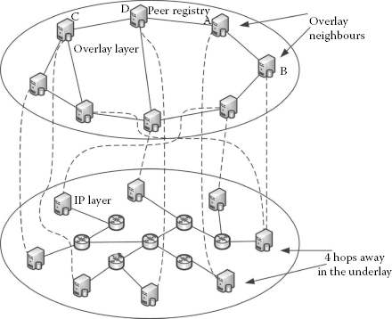
FIGURE 3.1
Mismatch between the overlay and the underlay topology.
1. P2P traffic redundantly uses different ISPs as transit nodes without any kind of optimisation.
2. ISPs need to spend lots of effort on traffic management.
3. This can lead to huge congestion and affects the performance of the network as a whole.
4. All of the above tremendously increase the cost of ISPs.
To this end, there has been a considerable amount of effort made by researchers around the globe. This section will review those works and how this research work is different from those works will be elaborated.
PIPPON [2] attempts to bring the underlay awareness to the overlay by clustering the peers based on proximity. The proximity of the peers is measured with two parameters:
1. Longest prefix IP matching
2. Round trip time (RTT)
Apart from cluster formation, it forms a dynamic ‘key tree’ for routing the query messages on the overlay. This tree is employed to route the queries based on the IP prefixes. However, PIPPON does not take into account the similarity of queries in the service discovery, which is a key factor in improving the efficiency. Also, it does not solve the problem of redundant traffic in the underlay.
(3.1) |
TOPLUS [3] has adopted a slightly different approach to PIPPON in terms of underlay awareness. The cluster formation in TOPLUS involves three tier hierarchies such as groups, super-groups and hyper-groups so that the queries can be easily forwarded with a minimal number of hops. In contrast to the longest prefix match of the IP addresses, TOPLUS makes use of the Exclusive-Or (XOR) metric for identifying the proximity. The distance d(j,k) between the two nodes j and k can be expressed in the XOR metric as shown in Equation 3.1. The range for the summation in Equation 3.1 is the number of bits in the IP address, which is 32(0–31). In each tier, the routing of the query messages is performed with the XOR metric. TOPLUS claims that the routing performance it provides is very close to IP routing. TOPLUS does not cover the aspects of inter-ISP, redundant traffic and interlayer communication overhead.
In general, there are two approaches with respect to finding the locality information of the underlay:
1. Dynamic (on the fly calculation with RTT and longest prefix match [LPM])
2. Static (prior knowledge of the Internet such as autonomous system [AS] numbers)
Plethora [4] follows the second approach, that is static, whereas TOPLUS and PIPPON follow the first approach. Plethora makes use of cSpace, which makes use of a local broker, and gSpace, which makes use of a global broker. Hence, it ends up with a two-layer architecture. If a request is generated, it checks cSpace for answers; if cSpace is able to answer it, then the query is not forwarded to gSpace. It only forwards it to gSpace if the query is not answered by cSpace. Here again, it does not cover the problems that are addressed in this research work.
P4P [5] addresses the locality awareness problem by two interfaces, iTrackers and appTrackers. The purpose of iTrackers is to provide the locality parameters of a particular node to the querying node. iTrackers are designed to reside in each of the ISPs. appTrackers are designed to reside globally so that they have a complete picture of the P2P applications. appTrackers decides whether a particular peer a could establish a neighbour relation with another peer b based on the information from iTrackers.
Internet engineering task force (IETF) formed an application layer traffic optimisation (ALTO) group in 2009 and has been tasked with identifying the means of optimising the traffic in the underlay that are generated by the ever-increasing P2P applications. Seedorf et al. [6] elaborate on the effort of the ALTO group, which intends to provide the ALTO service to the P2P applications. As per the ALTO approach, any P2P application that needs to know the topological and proximity information could obtain the same from the ALTO server. Information such as topology, operational cost and policies from the ISPs could be provided to the querying peers. In this approach, letting the peers be aware of these network-related parameters could be misused by any malicious user.
SLUP [7] is another approach that forms clusters based on semantics and RTT. It forms a three-tier clustering: normal peer, level-2 super peer and level-1 super peer. Redundancy in the underlay and ISP considerations are not in their scope.
Bindal et al. [8] have provided a strategy for improving the traffic locality in the BitTorrent network. They highlight that ISPs often end up throttling the P2P traffic as BitTorrent-like systems do not take ISPs’ cost into consideration. Their work focuses on biased neighbour selection in which a peer chooses the majority of its neighbours from the same ISP so as to reduce the cross-ISP traffic. The authors point out here that if there are N users within the ISP wanting to download a particular file, then in the current BitTorrent system, the file is downloaded N times, which heavily increases inter-ISP traffic. In their work, they have demonstrated that biased neighbour selection could improve this situation. Here, their application is specific to the BitTorrent system that uses the rarest first-piece algorithm at the client side. Our work differs from Bindal et al. [8] by providing a generic solution for the service discovery mechanism with improved performance.
To relieve the tension between the P2P applications and ISPs, Shen et al. [9] have provided an HTTP-based approach for P2P traffic caching. As ISPs already have cache proxies for web traffic, they propose to encapsulate the P2P traffic into the HTTP so that P2P traffic can also be cached by the same set of proxies. Their focus is on just providing a caching mechanism for the P2P application and providing an architecture infrastructure, for SD is out of their scope.
P4P Pastry [10] is an approach to bring the locality features to the PASTRY [11] structured system.
3.4.2 Message Level Intelligence
The ever-increasing demand for Internet business and entertainment applications has warranted the need for moving some of the processes from the end nodes to the networking components such as routers and switches [12]. IMR is needed even in the core routing process for the success of the next-generation Internet [13]. CISCO responded by introducing the concept of AON in 2005. AON can enable IMR and switching. CISCO has introduced the AON module into its component, which can differentiate between normal and AON-specific packets [14]. AON-specific packets are checked for their message contents and routing or switching decisions are made as per the AON module.
The approach in this research is to perform content-based routing of queries with the help of AON [14]. Since the introduction of the AON concept by CISCO, it has been a widely researched area in terms of its applicability in various areas of networking. AON is applied in the DSD process so that query routing is performed in the IP layer independent of the overlay layer.
Cheng et al. [15] have provided a model based on a holistic approach with an AON for autonomic service composition. Their focus is on combining the service oriented architecture (SOA), AON and autonomic service computing so that the problems of scalability and time to market products could be addressed collectively, which are handled individually otherwise. In this work, the authors have provided a scheme; however, they have not provided a concrete implementation model.
Xiaohua et al. [16] have improved the definition of AON introduced by CISCO and have given a more generalised approach called ‘Application Oriented Studies’. Part of our research comes under this category of studies as it has explored the possibility of employing AON in the SD routing process in the underlay. In this work, the authors have provided a multicast approach that can replace the overlay-based multicast that is usually poor in performance and scalability. However, their approach does not provide a concrete implementation model for DSD.
Yao et al. [17] have provided a mechanism for AON-based switching that can perform effective message scheduling at data centres.
Zille Huma et al. [18] discussed the service location problem (SLP) on how a particular service could be placed in the network so that AON could perform with better time efficiency. Here, their focus is on assisting AON with SLP and not exactly on AON itself.
The application of AON in the area of DSD by providing a query routing process in the underlay (IP layer) that is capable of mapping the service classes to the geographical location on the target registries is the focus of this research work, and it is the first effort of its kind.
3.5 P2P-Based DSD Routing Architecture
3.5.1 Layered Design of the Current P2P-Based DSD Systems
In general, the current P2P system can be abstractly divided into three layers. The network (IP) layer is completely isolated from the P2P system. The IP layer does not have a clue about what kind of message it is forwarding. Therefore, the IP layer does not consider the packet content of the P2P applications.
Also, layers 2 and 3 of the P2P systems function completely independently of the IP layer and the physical topology. Layer 2 is where the core P2P protocols such as Chord [19], Kademlia [20] and so on are implemented. Finally, layer 3 is where application-specific modules such as semantic matching and ontology matching are implemented. In Figure 3.2, the L2 and L3 modules are implemented in the peers (service registry). Henceforth, both the neighbour selection process and the query routing mechanism are implemented in the overlay, making it IP oblivious.
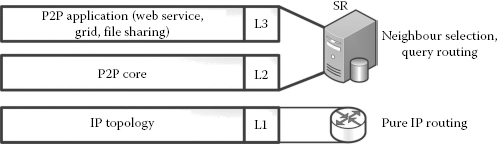
FIGURE 3.2
Layered approach—current P2P systems.
3.5.2 Layered Design of the Proposed P2P-Based DSD Systems
As the issues with the current approach to P2P systems are explained in Section 3.4, the goals for the architecture design of the proposed system have emerged clearly:
1. Enhanced security: As it was highlighted in the literature review, the present topologically aware query routing mechanism obtains the network-related parameter such as AS number, geographical location and so on from the ISP and passes it to the overlay peers, enlightening them with topological awareness. However, malicious users or compromised peers could misuse the system to launch attacks and destabilise the system. To prevent this, it is proposed that the network-aware query routing must be delegated to the underlying layer and kept transparent to the overlay layer [21,22].
2. Reduced inter-ISP traffic: Most of the P2P traffic on the Internet today uses intermediate nodes as the transit node, which belongs to a particular ISP. These ISPs may have to process a lot of intermediate traffic that would stress them to the limit and cause issues such as bandwidth throttling and high cost. In view of this, the second design focus of this research is to let the query-forwarding traffic enter a particular ISP domain only if it hosts the targeted service registry so that transit traffic could be minimised [22, 23, 24].
3. Minimised overlay process overhead: Every time a peer receives a packet and a routing decision is made in the overlay, the packet goes until it reaches the application layer. The third design goal is to minimise this overhead by letting the query reach the overlay layer only if it is a targeted peer. Other intermediate forwarding decisions are made in the underlay itself. This approach would eliminate the involvement of intermediate registries (peers) in query processing and, in turn, the processing overhead [23].
4. Interoperability: The Internet is very huge and it cannot be guaranteed that the underlay-based queries always pass through AON routers. Our final design goal is to integrate seamlessly with non-AON routers, if encountered, along the path of query forwarding.
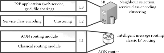
FIGURE 3.3
Layered approach—proposed P2P system.
Considering the goals listed above, a novel service discovery architecture has been designed as shown in Figure 3.3. The major modifications to the existing P2P systems are at layers 2 and 1.
As per the design goals, interoperability is one of the major concerns for the success of AON routing. Moreover, we propose AON routing as an additional service offered by the router on top of the classical routing. Consequently, at layer 1, pure IP routing has been split into two sublayers, namely, the AON routing module and the classical routing module.
• Classical routing: The classical routing module carries out classic (legacy) IP level routing based on network layer parameters.
• AON routing: The AON routing module is an additional module that is capable of carrying out IMR. IMR is a process in which a router can make routing decisions based on the content of the message instead of the IP headers. Making use of this IMR feature of the architecture is leveraged by the design at layer 2.
Layer 2 of the architecture performs two important functions, namely, service class encoding and peer clustering.
• Service class encoding: The services published on the registries by various participating entities such as users, organisations and so on are classified into different categories as per the Global Industry Classification Standards [24] as shown in Table 3.1. These codes in the messages are used for classifying the services. There could be a semantic encoder running at layer 2, which maps the service description to class codes. At this layer, the output needed for the approach is given a query; the service class encoder function should take the query as an input and provide a set of classes in which the query belongs as shown in Equation 3.2. The details of this semantic encoder are out of the scope of this research and from now on, it will be assumed that such an encoder exists. This assumption is valid as it will not affect the outcome of this research.
Partial List of Service Classification
Industries |
Class Codes |
Air freight and logistics |
20301010 |
Airlines |
20302010 |
Hotels, resorts and cruise |
25301020 |
Leisure facilities |
25301030 |
Restaurants |
25301040 |
(3.2) |
• Clustering: As pure unstructured P2P systems do not scale well, it has been adapted to use a hybrid structure by means of a clustering mechanism. As one of the design goals is the reduction of inter-ISP traffic, our clustering is ISP based. Peers belonging to a particular ISP are clustered together by electing a super peer. In this approach, the first service registry registering with the ISP becomes the super peer, otherwise called the SR. There are many other approaches [25] available for selecting the super peer, which can also be employed in this process. The way super peer is selected is also not included in the scope and will not affect the outcome of this research.
Layer 3 is similar to the current P2P system, where application-specific modules such as semantic matching and ontology matching are implemented.
The main features of the proposed architecture are
• The query routing mechanism for service discovery has been moved down to the IP layer. With the advent of service class encoding, the AON module at the IP layer is capable of bridging the information gap regarding the proximity of the nodes between the overlay and the underlying topology.
• The neighbour selection process is delegated to the AON module, where the neighbours are learnt dynamically.
The aspects regarding how this architecture can be made to fit with the current Internet infrastructure and the role of ISP in the proposed architectures are discussed in the following section.
3.5.3 ISP Level Perspective of the Proposed System
ISPs need to play an important role in underlay query processing as they are the key players in providing the service.
Any organisation, company or DSD system that needs to use underlay query processing would have to register themselves with the system. ISPs use the registration list to cluster those service registries in the organisation with the SR. The ISP needs to make sure that SR always uses the AON router when sending out query messages for discovery. Figure 3.4 depicts SR within an AS under the control of an ISP. Also, Figure 3.4 clearly shows the overlay links among the overlay neighbours and the physical links in the underlay. The SR in a particular AS is responsible for accepting and forwarding queries on behalf of users present in its AS.
3.5.4 Design of an Underlay Layer Query Routing Algorithm
AON routers are capable of making routing decisions based on application level messages. This feature fits quite nicely into the DSD. Any query generated from an AS is forwarded to the SR in its AS, which classifies the query into one or more of its service classes. Then, the query is encapsulated with its service class and forwarded to its nearest AON router. The packet structure in the IP layer is designed to record the interface(s) of the intermediate routers through which a particular router has received its query request or reply along with the intended source and destination IP addresses. The AON router uses these recorded fields in the header to inspect and update its AON-specific routing table, which is used for query routing. The query routing algorithm is shown in Figure 3.5.
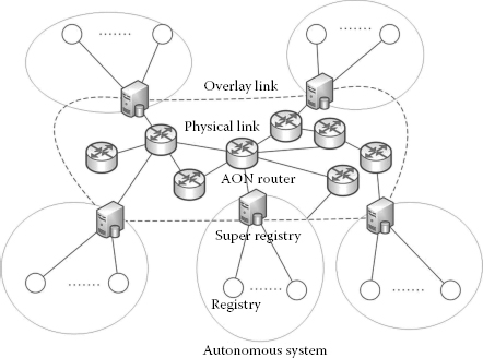
FIGURE 3.4
ISP level view of DSD architecture.
It is important to note that the algorithm in this research does not assume that all the packets entering the router are AON packets. Instead, it checks that the incoming packet is indeed an AON packet or not. The motivation behind this implementation is due to the fact that the existing services on the Internet are not to be interrupted due to the AON service. The AON service has been implemented as an additional service on the existing infrastructure of the Internet.
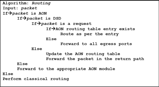
FIGURE 3.5
Query routing algorithm.
There are two stages in the query routing process, namely, the learning state and steady state. During the learning state, the AON routing table would be empty, and hence all incoming queries are forwarded to all egress interfaces of the router, which is in contrast to classical routers where the packets are dropped if there is no route to a particular destination. During the reply stage of this routing process, routers would eventually learn the routes for the service classes by inspecting the packet for the preceding node through which the query reply has been received. It is worth noting that a single query can span one or more classes depending on the user request. Once the routes are learned, the router enters the steady state and any further queries are forwarded in a single (common) path without duplication to a certain router from which the queries are distributed to multiple targets. This particular router is termed as a proxy router that forwards the query on behalf of the query initiator.
3.5.5 Underlay (AON) Query Routing Process
The current IP layer packet structure is designed to record the interface(s) of the intermediate routers through which a particular router has received its query and reply along with the intended source and destination IP addresses. This feature can be easily incorporated with the help of extension headers in the IPv6 format or within the payload in the IPv4 format. The AON router uses this feature to inspect and update these fields and its AON-specific routing table that is used for selective query forwarding to multiple SRs. This approach, which is multicast in nature, does not maintain any group memberships and forwarding is purely based on the AON-specific routing table. Our design is in such a way that the whole system, including the AON router, is interoperable with the existing classical routers in the Internet. There is every chance that the AON router will encounter non-AON packets as well. For this reason, every packet is inspected for its type as soon as it enters the router. The possible scenarios that could be encountered during query forwarding are depicted in Table 3.2.
Figure 3.6 illustrates a scenario of four ASs, each with their own SRs, connected via AON routers. A query forwarded from an AS is received by the border routers of the ASs, in this case, router R1. Figure 3.6 demonstrates a sample query forwarding from SR1 to SR2, SR3 and SR4 during the learning state. In the initial state, the AON routes are not yet learnt, and therefore the query is forwarded through all interfaces of the router except for the incoming interface. It is worth noting here that when queries are forwarded from one peer to another, a connectionless protocol such as UDP is used. There is no need to maintain the connection as the queries are independent of each other. The looping of the query is prevented by providing a unique ID for each query so that the router does not forward the query if it has already done so. During this state, the AON routing table is updated along the path of the reply, as shown in Equation 3.3, where r refers to the existing routes of the routing table RT and rnew refers to the new routes learnt through the query reply Qreply. Figure 3.7 demonstrates a typical scenario of the steady state in query forwarding. SR1 forwards the query to its border router R1. AON router R1 inspects the query and finds that this query should be forwarded to R2 as per its AON routing table and this process continues until the query reaches its destination. The same process is used if a query could be answered by multiple SRs, in which case queries are forwarded to more than one SR.
Possible Scenarios Encountered in Query Forwarding
Router |
Packet |
Remark |
AON |
AON |
Routing based on extension headers (message level intelligence) |
AON |
Non-AON |
Classical routing based on IP header |
Non-AON |
AON |
Classical routing based on IP header |
Non-AON |
Non-AON |
Classical routing based on IP header |
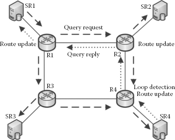
FIGURE 3.6
Query routing in learning state.
(3.3) |
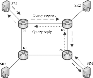
FIGURE 3.7
Query routing in steady state.
Routing Analysis for the Given Scenario
Query Propagation Method |
Number of Peers Involved |
Number of Links Involved |
Flooding (selects all 3 neighbours) |
4 (SR1, SR2, SR3 and SR4) |
13 (SR1 → R1 × 3, R1 → R2 × 2, R1 → R3 × 2, R2 → R4, R3 → SR3, R4 → SR4 × 2, R3 → R4 and R2 → SR2) |
Random/probabilistic (selects 2/3 neighbours) |
3 (SR1, SR2 and SR4) |
7 (SR1 → R1, R1 → R2 × 2, R2 → SR × 2, R2 → R4 and R4 → SR4) |
AON based |
2 (SR1, SR4) |
4 (SR1 → R1, R1 → R2, R2 → R4 and R4 → SR4) |
In pure overlay-based routing, for instance, Gnutella-like systems, considering the worst-case scenario (flooding), a query from SR1 to SR2, SR3 and SR4 would generate traffic along the paths SR1 → SR2, SR1 → SR3 and SR1 → SR4. Particularly, the link R1 → R2 and R1 → R3 would carry the same request twice as the routing is performed in the overlay. However, if AON routing is employed, the traffic generated is just along the path SR1 → SR4. Even during the learning stage, the redundant queries are eliminated. This clearly illustrates that ineffective query propagation could effectively be overcome by AON to improve the efficiency of the search mechanism. The same can be visualised in terms of inter-ISP traffic as well. In our illustration, the only inter-ISP traffic is from the source to the AS in which the target SR resides, as the intermediary peers are not involved in query forwarding, whereas in overlay routing, all the four peers belonging to different ISPs are involved in query processing. The performance can also be improved in the case of the other query-forwarding heuristics such as random or probabilistic selection of neighbours that is summarised in Table 3.3. In this and the previous sections, the role of an AON router and what it has to accomplish has been elaborated. The design of the AON router follows next.
Figure 3.8 shows the structure of the AON router inspired from Ref. [14]. It has been devel-oped for the purpose of message level routing. The main additional components to the normal router are the classifier, AON routing module and AON routing table. In the AON router, all incoming packets are inspected for their type as shown in Equation 3.4.
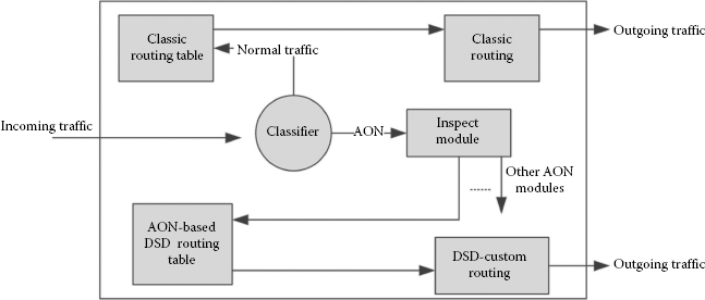
FIGURE 3.8
Model of an AON router.
The classifier first inspects the incoming packet to determine if it is normal or AON based; if it is normal, the packet is diverted to the classic routing module. If the packet is AON, it needs to be further checked for what specific service needs to be offered to AON. The specific service in our case is DSD; however, in future, there may be more AON services that could be offered for the application layer.
(3.4) |
3.5.7 AON-Based Query Message Structure
So far, the AON router design and the algorithm design for the query routing have been seen. Now, let us have a closer look at the AON message structure that is used in the query routing process. The AON-based query routing message has been designed as shown in Figure 3.9. This message body is sent by encapsulating the IP header. Once the router has identified the AON packet, it makes use of the other fields in the message for IMR as per the algorithm in Figure 3.5.
• Request/reply: The query routing algorithm makes use of this field to distinguish between the request and the reply message. During the reply messages, the AON-based routing table is updated.
• Timestamp: This field is used to calculate the RTT.
• Query message: This field is used to carry the actual query message that needs to be searched. This contains the service class information that is used by the AON router.
• Result: This field is used to store and send the result of the search back to the source.
• Is AON: This field is used to identify the AON packet. For the sake of this simulation, the AON field has been built inside the AON message itself. However, in realtime implementation, this could be applied into IPv6 extension headers.
• Previous node: This field is used to learn the previous node that the router has passed through. This information, along with the service class, is used for updating the AON routing table during the reply path.
• Hop count: This field is used for the purpose of data collection regarding the number of hops crossed by each query. In real-time mode, this field would not be necessary.
• Query ID: This field is used for preventing loops in the query forwarding.
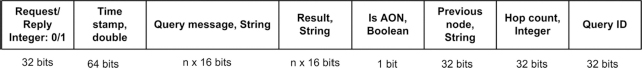
FIGURE 3.9
AON query structure.
3.6 Performance Comparison of Underlay versus Overlay Routing
The routing complexity in the underlay is always less than that of the overlay.
Proof 1:
Figures 3.10 and 3.11 depict the connection of SRs in the underlay via routers. The structure can be modelled to be a tree of order 2 with n levels for the sake of this analysis.
Analysis scenario: Let us consider that a user issues a query in the DSD system. The SR in the AS distributes the query into the system. Let us also assume that there are eight neighbours to the SR and that the topology is as shown in Figure 3.10.
Let us consider the worst-case scenario that all the neighbours are well distributed in the underlay as shown in Figure 3.10 for the overlay routing and Figure 3.11 for the underlay routing.
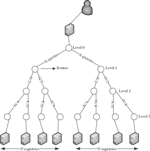
FIGURE 3.10
Overlay routing scenario.
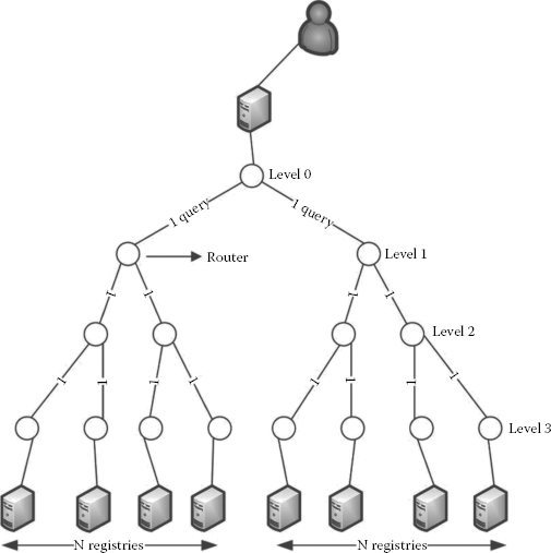
FIGURE 3.11
Underlay (AON) routing scenario.
3.6.1.1 Estimation of the Number of Routers Crossed in the Overlay
Let n be the number of levels in the tree with a degree of 2. Then, the number of leaf nodes in the tree can be written as 2n–1. This value also corresponds to the number of neighbours. The number of routers passed by overlay routing is n ⋅ 2n–1.
It is worth noting here that though the number of routers in each level decreases when moving from the leaf nodes to the root, the number of query messages passing through each level remains the same, which is shown in Figure 3.10. This is due to the redundant transmission that is caused by the underlay’s ignorance of overlay routing.
3.6.1.2 Estimation of the Number of Routers Crossed in the Underlay
As shown in Figure 3.11, there is no duplicate query transmission in the links in the underlay when employing AON-based routing. This is due to the fact that the query mes-sages are forwarded as per the AON routing table in the AON router and it is clearly aware of which interface the query needs to be forwarded to. The SR submits the query just once to its connected AON router; thereupon, the AON routers handle query routing. In contrast to this, in overlay routing, query routing is carried out by the end peers (SRs). Keeping these factors in mind, now let us estimate the number of routers crossed in underlay routing.
The number of leaf nodes in this scenario would be the same, which is 2n–1.
The number of routers crossed in each level of the tree is 0, 2, 4 and 8 for the given topology.
The number of routers crossed can be generalised as 2n–1 + 2n–2 + 2n–3 + ⋅ + 20.
The numbers of routers crossed have been estimated both in overlay and in underlay routing. To analyse the complexity of query processing, the complexity of routing a packet in the router needs to be found.
The complexity of routing a packet is given as O(1) [26].
Knowing that if the complexity of routing a packet in a router is O(1), then the complexity analysis of the routing process solely depends on the number of routers crossed.
Therefore, in the overlay, the complexity would be O(n ⋅ 2n–1), whereas that of underlay routing is O(2n–1 + 2n–2 + 2n–3 + … + 20) ≈ O(2n–1) [26,27].
O(2n–1) < O(n ⋅ 2n–1), and hence the proof.
The number of links utilised in underlay routing is always less than that in overlay routing.
Proof 2:
Let us consider that a query needs to be forwarded from registry r0 in AS0 to r2 in AS2. Let LST be the number of links between peer registries r0 and r2.
3.6.2.1 Estimation of the Number of Links Utilised in the Overlay
As shown in Figure 3.12, if a peer has n neighbours, then the total number of links nl utilised at the overlay is given by
(3.5) |
3.6.2.2 Estimation of the Number of Links Utilised in the Underlay
In AON-based query routing in the IP layer, LST could be divided into LSP and LPT as shown in Figure 3.13, where LSP is the number of links between the source and the proxy and LPT is the number of links between the proxy and the given target.
If there is more than one neighbour in the overlay for a node, the queries are sent redundantly in the underlay layer. To prevent the redundant query propagation in the underlay, this AON-based routing algorithm identifies a particular router until which the query need not be duplicated by way of updating the AON routing entries. In these scenarios, router C is termed as the proxy router from which the fanning out of the queries to the multiple registries starts. In general, during the steady state of AON routing, proxies from all directions are learnt by means of updating the AON routing table during the return path. The proxies are learnt dynamically depending on the current state of the system.
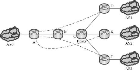
FIGURE 3.12
Links utilised—overlay routing.
Thus, the total number of links utilised in the AON-based IP layer is
(3.6) |
The percentage of the savings in terms of link utilisation for AON-based query processing to that of the overlay is
(3.7) |

FIGURE 3.13
Links utilised—AON routing, learning state.
From Equation 3.7, the complexity of query forwarding can be inferred as
(3.8) |
On the basis of Equation 3.8, it can be observed that a higher percentage of saving can be obtained if nlpt is much smaller compared to nlst, so that the complexity of query forwarding could be brought closer to
(3.9) |
To achieve a high percentage of reduction in the underlying traffic, the proxy should be as close as possible to the target registries, which would result in shorter nlpt compared to that of nlsp. This is achieved by the current AON-based implementation as it detects the closest possible proxy to the target.
Redundant traffic caused in the overlay is eliminated by the underlay query routing process.
Proof 3:
Let us consider Figures 3.12 and 3.13 for this proof.
If a query message is sent from the source (AS0) to different destinations (AS1, AS2 and AS3), then the redundant traffic can be measured by identifying the common path between the source and the destinations.
From Equation 3.5, it can be inferred that the overlay routing cannot differentiate between LSP and LPT, and therefore redundancy is caused by sending the same query messages, a number of times that is equal to the number of destinations.
However, underlay query routing is capable of differentiating between LSP and LPT and does not duplicate query messages along the path of LSP.
The inter-ISP traffic is always reduced in underlay query routing.
Proof 4:
Let us consider Figures 3.12 through 3.14 for proving this.
Let us assume that AS0, AS1, AS2 and AS3 belong to different ISPs. The inter-ISP traffic could be measured by ASs that receive the query messages.
3.6.4.1 Inter-ISP Traffic in Overlay Routing
In Figure 3.12, routers B and C that are in between the source and the destination would be in different ISPs and therefore handle the transit traffic of query routing.
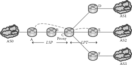
FIGURE 3.14
Links utilised—AON routing, steady state.
Overlay routing is not capable of detecting the transit ISPs, and therefore the inter-ISP traffic is proportional to the number of target registries m and the number of routers n along the path, which can be expressed as
(3.10) |
3.6.4.2 Inter-ISP Traffic in Underlay Routing
Let x be a factor by which the proxy node C is closer to the target registry. In other words, x represents LPT in Figure 3.13. Therefore, with reference to Figure 3.13, n – x corresponds to the portion of the topology LSP and m ⋅ x corresponds to the portion of the topology LPT. Hence, the inter-ISP traffic for the underlay routing is as shown below in Equation 3.11, which is reduced to a factor of x
(3.11) |
If x = 0 (negligible) when compared to the distance between the source and the target, then there is a higher percentage of reduction in the inter-ISP traffic.
Moreover, routers D, E and F are the destination routers that receive the query message. Among D, E and F, only a subset, for example, {D,E}, {E,F}, {D,F}, {D}, {E} or {F} and in the worst case, {D,E,F}, would have the results for the queries that are received. Inter-ISP traffic is reduced in this approach as well as depicted in Figure 3.17 in the case of underlay routing.
The time taken for query routing in the underlay is less than that of the overlay.
Proof 5:
Let μ be the processing time taken by the overlay registry, α the processing time taken by the routers and β the time taken for each of the link propagations.
Then, a query to be sent to m neighbours by a source registry in overlay query routing is given by the following equation:
where n is the number of routers in between the source and the targets.
Let us now calculate the time taken for a query to be sent to m neighbours in the underlay. The nodes in the underlay can be divided into two sections: as LSP and LPT as per Equation 3.6.
A query to be sent from a source to a proxy node is given by
A query to be sent from the proxy to m neighbours is given by
Therefore, in underlay query routing, a query to be sent from a source registry to all its neighbours is given by the following equation:
(3.13) |
Here again, it can be clearly observed that the time taken is considerably reduced depending on the location of the proxy. In Equation 3.13, x is the fraction that determines the factor of the proximity of the proxy router to the target registries.
Router performance: The AON router model was designed to have additional modules such as a packet classifier, an AON-specific routing table and an AON-specific inspection module. These additional modules could cause overhead to the routers and would demand higher processing and memory capacity from the routers. However, it has been argued that with the tremendous increase in processing power and memory capacity of the current routers, this issue could be resolved.
Involvement of ISPs: The design and implementation of the AON-based DSD relies on installing AON routers on the Internet backbone, which could only be provided by service providers and not by consumers. Therefore, ISPs play an important role in providing AON services to its customers. There could be additional costs incurred by the ISPs for providing the AON infrastructure to the customers. If ISPs are not willing to provide the AON services, then the success of the system cannot be guaranteed in real-time implementations.
Involvement of the participating organisations: The routing algorithm employed depends on looking into the contents of query messages. The AON routers would inspect every AON packet that passes through. Therefore, there needs to be a good understanding in terms of security and reliability between the service provider and the clients. A security mechanism has been provided for AON implementation to keep the messages from the prying eyes of intruders. However, the router itself needs to look into the messages, which is only possible with clients willing to participate in the DSD process.
This chapter provided a novel implementation of underlay query routing for the DSD process. It elaborated how AON is implemented for incorporating IMR. It also provided a novel query routing algorithm that runs in the underlay. The benefits obtained by the proposed architecture and the query routing algorithm were proved hypothetically.
The following are the possible future works that need attention for the successful implementation of the proposed system in real time and also to study the possibility of the emerging AON technology in other domains such as computational grids and cloud computing.
1. There is a need to study how ISPs could be encouraged to provide AON services. The reduction of the cost due to the reduced inter-ISP traffic could be one of the incentives.
2. The focus in this research has been on the DSD process. Its applicability in file sharing and downloading systems such as BitTorrent needs to be studied.
3. In this research, the clustering mechanism is based only on ISPs. The performance of the system while clustering the peers purely based on service classes needs to be studied.
4. The effect of the clustering of the registries across ISPs also needs to be studied.
5. In this research, the system built for testing employs hybrid architecture with an unstructured backbone. However, the possibility of employing IMR in structured distributed systems needs to be studied.
1. S. James et al., IMP: ISP-managed P2P, in IEEE 10th International Conference on Peer-to-Peer Computing (P2P), Delft, Netherlands, 2010.
2. D. B. Hoang, H. Le and A. Simmonds, PIPPON: A physical infrastructure-aware peer-to-peer overlay network, presented at TENCON 2005, IEEE Region 10, 2005.
3. L. Garcés-Erice et al., Topology-centric look-up service, in Group Communications and Charges. Technology and Business Models. Vol. 2816, B. Stiller et al., eds., Springer, Berlin, 2003, pp. 58–69.
4. R. Ferreira, A. Grama and S. Jagannathan, Plethora: An efficient wide-area storage system, in High Performance Computing—HiPC 2004, Vol. 3296, Lecture Notes in Computer Science, L. Bougé and V. Prasanna, eds., Springer, Berlin, 2005, pp. 305–310.
5. H. Xie et al., P4P: Provider portal for applications, presented at the Proceedings of the ACM SIGCOMM 2008 Conference on Data Communication, Seattle, WA, USA, 2008.
6. J. Seedorf et al., Traffic localization for P2P-applications: The ALTO approach, in P2P ‘09. IEEE 9th International Conference on Peer-to-Peer Computing, Seattle, USA, 2009, pp. 171–177.
7. S. Xin et al., SLUP: A semantic-based and location-aware unstructured P2P network, in 10th IEEE International Conference on High Performance Computing and Communications, HPCC ‘08, Dalian, China, 2008, pp. 288–295.
8. R. Bindal et al., Improving traffic locality in BitTorrent via biased neighbor selection, in 26th IEEE International Conference on Distributed Computing Systems, ICDCS 2006, 2006, pp. 66–76.
9. G. Shen et al., HPTP: Relieving the tension between ISPs and P2P, in USENIX IPTPS, 2007.
10. G. Zhengwei et al., P4P Pastry: A novel P4P-based Pastry routing algorithm in peer to peer network, in The 2nd IEEE International Conference on Information Management and Engineering (ICIME), Chengdu, China, 2010, pp. 209–213.
11. A. Rowstron and P. Druschel, Pastry: Scalable, decentralized object location, and routing for large-scale peer-to-peer systems middleware, In Lecture Notes in Computer Science, Vol. 2218, R. Guerraoui, ed., Springer, Berlin, 2001, pp. 329–350.
12. A. A. Bare, A. P. Jayasumana and N. M. Piratla, On growth of parallelism within routers and its impact on packet reordering, presented at 15th IEEE Workshop on Local & Metropolitan Area Networks, LANMAN 2007, Princeton, NJ, 2007.
13. Cisco-white-paper, The evolution of high-end router architectures: Basic scalability and performance considerations for evaluating largescale router designs, Available: www.cisco.com/en/US/products/hw/routers/ps167/products_white_paper09186a0080091fdf.shtm.
14. CISCO, Cisco AON: A network embedded intelligent message routing system, Available: www.cisco.com/en/US/prod/collateral/modules/ps6438/prod_bulletin0900aecd802c201b.html.
15. Y. Cheng et al., Toward an autonomic service management framework: A holistic vision of SOA, AON, and autonomic computing, IEEE Communications Magazine, 46, 138–146, 2008.
16. T. Xiaohua et al., Multicast with an application-oriented networking (AON) approach, in IEEE International Conference on Communications, ICC ‘08, 2008, Beijing, China, pp. 5646–5651.
17. J. Yao et al., Intelligent message scheduling in application oriented networking systems, in IEEE International Conference on Communications, ICC ‘08, 2008, Beijing, China, pp. 5641–5645.
18. K. Zille Huma, A.-F. Ala and G. Ajay, A service location problem with QoS constraints, in Proceedings of the 2007 International Conference on Wireless Communications and Mobile Computing%@ 978-1-59593-695-0. Honolulu, Hawaii, USA: ACM, 2007, pp. 641–646.
19. S. Ion et al., Chord: A scalable peer-to-peer lookup service for Internet applications, SIGCOMM Computing Communications 31, 149–160, 2001.
20. P. Maymounkov and D. Mazières, Kademlia: A peer-to-peer information system based on the XOR metric peer-to-peer systems. Vol. 2429, P. Druschel et al., eds., Springer, Berlin, 2002, pp. 53–65.
21. J. Seedorf et al., Traffic localization for P2P-applications: The ALTO approach, in P2P ‘09. IEEE 9th International Conference on Peer-to-Peer Computing, Seattle, USA, 2009, pp. 171–177.
22. T. Karagiannis et al., Should Internet service providers fear peer-assisted content distribution?, in Proceedings of the 5th ACM SIGCOMM Conference on Internet Measurement, USENIX Association, Berkeley, CA, 2005, pp. 6–7.
23. E. Meshkova et al., A survey on resource discovery mechanisms, peer-to-peer and service discovery frameworks, Computer Networks, 52, 2097–2128, 2008.
24. MSCI, Global industry classification standard, Available: www.msci.com/products/indices/sector/gics/.
25. C. Mastroianni et al., A super-peer model for building resource discovery services in grids: Design and simulation analysis, in Advances in Grid Computing–EGC 2005, Vol. 3470, P. M. A. Sloot et al., eds., Springer, Berlin, 2005, pp. 132–143.
26. A beginner’s guide to big Oh notation, Available: rob-bell.net/2009/06/a-beginners-guide-to-big-o-notation/.
27. Some rules for big-Oh notation, Available: www.augustana.ualberta.ca/~hackw/csc210/exhibit/chap04/bigOhRules.html.