HOMERF
Two major factors are presenting a real opportunity for data networking within the home. The first is the explosive growth and usage of the Internet. The Internet has clearly revolutionized the delivery of information and entertainment to the home. The second factor is the emergence of sub-$1000 powerful home PCs. With these low-cost devices, the barrier to getting on the Internet and discovering the utility of the PC is low enough to reach the vast majority of middle-income households. However, consumers soon find that the PC/Internet combination, though very compelling, lacks some key attributes in terms of mobility and convenience of location compared with many of their traditional information and entertainment options—newspapers, maga zines, television, videos, FM radio, DVD/CD/stereo, etc. The powerful home PCs (and the printers and peripherals attached to them) often end up turned off 20 to 22 hours per day, tucked into a bedroom or den corner where access is possible only within a two to three foot "bubble." The major opportunity for networking in the home is thus to extend the reach of the PC and Internet throughout the home and yard, and connect the resources of the PC and Internet with legacy home applications such as telephony, audio entertainment, and home control systems. Another opportunity is the sharing of resources (such as an Internet gateway or high quality printer) among PCs in multi-PC homes. With these issues in mind, several major stakeholders in the PC industry formed the Home RF Working Group[4] in early 1997. The key goal of the group is to enable interoperable wireless voice and data networking within the home at consumer price points. The group began by pooling market research from the member companies to produce a Market Requirements Document. This document guided the technical proposals within the group. With tremendous cooperation from major stakeholders in the RF communications industry, and the nascent wireless local area network (WLAN) community, the Shared Wireless Access Protocol-Cordless Access (or "SWAP-CA") was created. In designing SWAP-CA, the HomeRF Technical Committee chose to reuse proven RF networking technology for data and voice communications and added simplifications where appropriate for home usage. With this approach, SWAP-CA inherited native support for Internet access via TCP/IP networking, and for voice telephony via the Public Switched Telephone Network (PSTN) and Voice over IP. Additionally, because of this design approach, the HomeRF Working Group made rapid progress in finalizing the specification and bringing it to market in a timely manner. Table 8.1 contains the results of the research carried out by the HomeRF marketing subcommittee on user expectations for a home networking wireless technology. These expectations were used as a guide by the HomeRF Technical Team, which then made design decisions to best fulfill the needs of the potential users.
[4] The HomeRF section copyright (c) 2000 IEEE. Reprinted with permission. Adapted from "HomeRF: Wireless Networking for the Connected Home," by K. J. Negus, A. P. Stephens, and J. Lansford. IEEE Personal Communications, Volume 7, Issue 1, February 2000, pp. 20-27.
Three subcommittees exist within the HomeRF Working Group. The HRFWG-Japan subcommittee was created to assist in defining SWAP and ensuring that it complies with local regulations. The group has also formed committees to plan future versions of SWAP that address wireless multimedia and a lower-cost alternative. In addition to ratifying the standard, 13 companies have also committed to building products based on SWAP. Products that adhere to the SWAP standard will carry voice and data traffic between various portable appliances within the home without using a wiring system. Additionally, these products will interoperate with the public telephone network and the Internet. The remaining parts of this section on HomeRF describe the vision, design, and implementation of the HomeRF standard.
Vision and Usage Scenarios
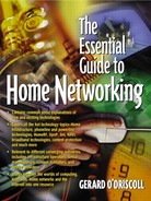
HomeRF sees SWAP-CA as one of several connectivity options in the home of the future. The relationship of SWAP-CA with other connection options is shown in Figure 8.2. In this scenario, the main home PC is linked to an Internet gateway that might be a 56K, xDSL, or cable modem. This link may be a simple cable, a wired network connection, or even a SWAP-CA network connection. This main home PC would likely have a variety of built-in or peripheral resources such as a printer, a scanner, a CD drive, a DVD drive, etc. For most home PCs today, and looking forward, it is likely that the USB would be the bus of choice for many peripherals that do not need to be mobile or remote from the PC. For video applications, which require connection to devices such as camcorders, the IEEE 1394 is the expected choice. For sharing resources among multiple PCs, options such as conventional 10/100 BaseT Ethernet, home phone line networks, and AC power line networks will exist. (This last option is particularly well suited for many home automation applications where very low data rates are acceptable). At this time, there are no viable RF alternatives at consumer price points that can be used as a wireless networking technology for home networks. The goal of the HomeRF Working Group is to fill this void. The SWAP-CA networking vision is apparent in Figure 8.2. The HomeRF technology supports both isochronous clients that are slaves to the main Home PC and an asynchronous network of peer devices that is effectively a wireless Ethernet. In most cases, the system starts with a connection point, usually connected to the main home PC via USB. This connection point is not absolutely necessary for devices in the asynchronous network of Figure 8.2, but even in that case it offers some interesting power-saving options for ultra-portable devices as described in the MAC overview section. The isochronous clients, such as cordless telephones, wireless headsets, or remote I/O devices to the home PC (a consumer Personal Information Manager or PIM) are always bound to the connection point, which assigns them guaranteed bandwidth for bounded latency communication. The asynchronous peers can also communicate with the main home PC as with any other peer device. We now consider three major applications for the HomeRF technology.
Figure 8.2. SWAP vision for home networking
Our first example is that of PC-enhanced cordless telephony. Today there are no standards-based digital cordless telephones for consumer use in the USA where interoperability of multiple vendors is enabled. HomeRF defines a new standard for interoperable digital cordless telephones both in the United States and globally. Furthermore, the SWAP specification includes a standard method for connecting the cordless telephone to the home PC software applications. Thus many new enhanced features are possible. For example, caller ID information could be sent to a PC application to look up the caller's name and then route the call to an individual handset (rather than a number) and display the caller's name on any given handset. For outbound calls, the PC could interpret a spoken destination name (e.g., "Call Mom") through voice recognition and then, based on date/time, determine the likely number for the person and route the call using the lowest cost approach (which might be IP telephony). The handset could be used to pick up voice mail for a specific user from the home PC call center.
With voice synthesis the handset could also be used to "listen" to e-mail. With more sophisticated application software, the handset could achieve PIM functionality by using voice or keypad I/O to store lists (e.g., "Add three quarts of milk to my shopping lists") or control home automation features (e.g., "Turn the temperature up three degrees"). All of these and undoubtedly much more creative features are possible because of the standard interoperable method of connecting to the Home PC. The cordless handsets themselves are slightly different but not substantially more complex or expensive than the existing "dumb" cordless handsets sold in multimillion unit volume today.
A second interesting example is a mobile viewer appliance. This could take many forms but fundamentally consists of a color LCD display (like that of a notebook computer) with some limited input device (such as a pen) and a SWAP-CA radio network connection. Such a device could be either an extension of the home PC (like an X-terminal) or simply a web-browsing extension of an Internet gateway. In either case the viewer communicates entirely through receiving and sending TCP/IP packets.
The third of many potential applications is resource sharing among multiple PCs in the same home. The resource to be shared could be a high quality printer, a back-up storage device, a file server, or an Internet connection. Another possibility for this is multiplayer gaming. Clearly these resource-sharing applications have received considerable attention from other home wiring-based alternatives to networking. It is important to note that the market for HomeRF is not strictly multi-PC homes. Any home with a modern home PC or an Internet gateway is a candidate for compelling mobile devices enabled by the SWAP-CA specification. Thus, the SWAP-CA protocol is a hybrid in several ways; it is client-server between the connection point and voice devices, but is peer-to-peer between data devices. The interactive voice transactions are circuit switched, but the asynchronous transactions are packet-switched. It is precisely this richness that gives SWAP-CA the capability to be broadly used in the home; it is not designed to support hundreds of users doing similar things in an enterprise, but rather the variety of applications that occur in a residential setting.
Before concluding this section, we briefly describe three usage scenarios that the SWAP-CA protocol was designed to enable. These were part of the marketing requirements document that the design team used as motivation for SWAP-CA. The primary focus in these scenarios is on the exchange of voice and data packets by portable devices within the home environment.
Scenario I: A Busy Family
Two children, sitting in different rooms, play interactive games with each other on their wirelessly connected handheld PCs. They talk to each other using the PC's mike and speakers.
A third child uses the Web for writing a school report from her room.
Mom listens to her phone messages, recorded by the PC answering machine application, while making dinner in the kitchen.
Dad completes an oil change in the garage. Using a handheld notepad, he enters the data into his car maintenance log, which he maintains on his desktop PC.
Scenario 2: A Montage of Voice Applications
Mom uses her personal handset to record a message for the kids to listen to when they return from school.
Dad asks for stock quotes from the Internet and gets an audio response through a TTS (text to speech) engine.
Dad checks the temperature in the bedroom and turns the space heater on via a voice command.
Uncle Ed listens to a soccer match on his wireless headset on the front porch. The match is being broadcast over the Web and transmitted by the PC to the headset.
Scenario 3: A Montage of Display Applications
While in the kitchen, Mom pulls up a recipe from the PC and adds oregano to the shopping list.
Dad updates the family financial portfolio.
Junior plays Tetris.
Daughter reads the latest online issue of Teen magazine while lying down on her bed.
In the scenarios described above, a common theme is tetherless multimedia connectivity between devices and to the Internet. Many companies are actively building SWAP-CA devices and software that will bring these envisioned scenarios to reality.
Network Architecture and Operation
In this section we describe the architecture of a SWAP-CA network and some of its key operational features.
The SWAP-CA network is designed to operate on the 2.4 GHz ISM band. The 2.4 GHz band is a nonlicensed frequency band that is available all over the world, ensuring that SWAP-CA devices would be operational globally. The protocol is unique in the way it combines with the ETSI Digital European Cordless Telephony (DECT) standard for carrying time-sensitive, real-time traffic.
Device Types
Four types of devices can operate in a SWAP-CA network:
A connection point (CP), which functions as the gateway between a SWAP-CA compatible device, the PSTN, and a personal computer (possibly connected to the Internet).
Isochronous nodes (I-nodes), which are voice-centric devices such as cordless phones and walkie-talkies.
Asynchronous nodes (A-nodes), which are data-centric devices such as handheld notepads and personal digital assistants.
Combined asynchronous-isochronous nodes (AI-nodes).
The connection point can either be a separate device, connected to the main (home) PC, typically via the USB connection, or can be an integral part of the PC. It can also have a direct connection to the PSTN. The CP is capable of performing data transfers to and from SWAP-compliant devices using both a contention-based and a contention-free protocol. When configured to do so, it can provide power management services to both A-nodes and I-nodes. Figure 8.3 shows an example of a typical SWAP-CA network consisting of two A-nodes, one I-node, and a connection point. .One of the A-nodes is a power-managed display pad whose communications traffic is managed by the PC so it can maximize battery life. Although not shown in this figure, the laptop A-node could also be power-managed. As this figure shows, SWAP-CA has a unique ability among networking protocols to mix intense, high-demand packet traffic with infrequent command and control traffic and high-quality real-time voice traffic. The personal computer is an integral part of the SWAP-CA system although peer-peer data networking is available even when the PC is inoperative. Every SWAP-CA device has a 48-bit IEEE MAC address, which is configured by the manufacturer prior to distribution.
Figure 8.3. SWAP network topology flexibility

Network Configuration
As shown in Figure 8.3, the HomeRF network is designed to operate in two basic modes: the network can be configured either as a managed network or as a peer-to-peer ad hoc network. In the managed network configuration, the network is explicitly under the control of a connection point, which is its gateway to other devices, the Internet, and the PSTN. Furthermore, it provides simultaneous support for both real-time audio traffic, such as interactive voice, and non-real time data traffic, such as traditional TCP connections. In the ad hoc network mode, the network provides traditional data networking support only and does not need a connection point for proper operation.
Multiple Overlapping Virtual Networks
Certain characteristics of radio frequency networks make them unique. One such characteristic is that radio frequency signals are not restricted to well-defined boundaries; consequently, a RF node can hear other RF nodes operating on the same frequency within its transmission range. It is likely that users of HomeRF equipment are interested in setting up their own independent networks with their own SWAP-CA nodes, but which happen to be within the range of other users'HomeRF equipment. Consequently, these networks may overlap
Scenarios like this can be fairly common in places such as an apartment complex where every apartment has a HomeRF network of its own, but since the apartments are close to each other, devices in one apartment are within range of devices in a neighboring apartment. Neighboring networks should in general not interfere and affect each other's performance. In SWAP-CA, a 24-bit network identifier (NWID) is used to separate the different overlapping virtual networks located in the same area of coverage. Devices having the same NWID are part of a logical network, and devices with a different NWID do not interact with one another. The network identifier is present as part of every data packet in the network. Depending on how a network device is configured, a node may either use the NWID assigned to it by the user, or alternatively, derive a NWID from a MAC address. For an existing network, new nodes can learn the NWID as they join the network. In general, different networks are not synchronized and use different frequency-hopping patterns.
Discovery and Creation of Networks
When a SWAP-CA node is turned on, it immediately enters into a network discovery phase in which it tries to determines if another node or connection point is present in its transmission range and if a network already exists that it can join. The node accomplishes its discovery phase by operating in a passive scanning mode. In passive scanning mode, the node listens on every channel within its operational frequency band for a specific amount of time, greater than a single superframe. "Listening" on a channel is accomplished by the physical layer, which forces the node to hop on a known scan pattern which is a good spread of the hopping patterns on all the channels of the network. During a scan, the node receives all network packets regardless of the NWID or destination address. These packets are analyzed by the node's MAC management module and a decision is made on whether or not to join the network. The scan can be terminated as soon as the first network is found, or when the management module so determines. When a network is found, the node sets its hopping pattern If the network identifier is known, SWAP-CA can join the known network by scanning all the channels for the NWID of interest and then locking-on to that channel. The scanning procedure is terminated as soon as the sought-after NWID is discovered. In case the node does not find a network with the particular NWID, it can either give up or start its own network. To start its own network, the node randomly selects an available hopping pattern, records the NWID as the network identifier, and starts transmitting synchronization signals. Not all nodes are allowed to create a network; specifically, a CP can create a managed network while an A-node can create a peer-to-peer ad hoc network. I-nodes do not create their own network. In a managed network, the CP is responsible for transmitting synchronization information, whereas in an ad hoc network all A-nodes participate in synchronization. Synchronization information contains the hopping pattern and the dwell time for the network and is transmitted by the CP as part of its beacon signal. A beacon signal is a broadcast packet transmitted by a node (a CP in a managed network) periodically. It contains information that the network devices need for proper operation within the network. When there are two or more devices in the network that are capable of CP functionality, the first one to join/create the network becomes the active CP while the remaining ones become passive CPs. When a passive CP does not hear 50 consecutive beacons from the active CP, it assumes that either the active CP has gone off-line or has moved out of range, and consequently creates its own network by transmitting synchronization information. If 100 or more simultaneous beacons are missed by the A-nodes in the network, they start the ad hoc network synchronization operation and create an ad hoc network. The entire process of scanning followed by either joining or forming a new network can take a few seconds.
Authentication and Privacy
As discussed, RF signals are not restricted to well-defined boundaries; consequently, unlike a wired network, an RF wireless network is difficult to secure. The transmission medium is open to anyone within range of the transmitter. Even when the physical layer of the network is based on spread-spectrum communication and different networks use different hopping patterns, the system is insecure as it is relatively easy for a malicious user to scan all channels and determine the hopping pattern and NWID of the target network. Thus, neighbors who receive RF signals from each other can conceivably "listen-in" on each other's conversations and intercept each other's data packets. This is clearly undesirable. Consequently, an encryption mechanism that provides security and privacy is clearly needed, and should be part of any wireless networking standard. Data privacy and authentication in a SWAP-CA network is accomplished by using a well-established shared-key encryption algorithm. Notably, all I-nodes follow the security model defined in the ETSI DECT specification. The authentication process in this model is split into a key generation process and the encryption process. The purpose for splitting this process is to support roaming of handsets between DECT base stations. HomeRF defines its authentication process in terms of the DECT security model. A node indicates that it supports encryption to the destination node as part of the capability exchange process. Data packets are encrypted only if the destination node can decrypt the message. The encryption algorithm takes a 56-bit key and a 32-bit initialization vector and uses these to convert unencrypted data (called plaintext) to encrypted data (called ciphertext). The initialization vector is a combination of the packet sequence number and a hash of the 48-bit MAC address of the source node. The sequence number keeps track of the number of packets the node has encrypted and prevents against replay attacks. A magic number, a byte containing all zeros, is appended to every packet before encryption. This allows the receiver to check, as it decrypts the packet, whether or not it has the right key. All A-nodes in the HomeRF network share a single common 56-bit key. The key may be entered though a Management Information Base (MIB), or computed dynamically. A MIB contains information that is used to manage the operation of a SWAP-CA node. This information can be used by higher-layer protocols to manage the node as well. A property of this algorithm is that the output ciphertext is of the same length as the input plaintext and the encryption algorithm is symmetric (i.e., decryption performs the same process as encryption). The core of the encryption algorithm is common to both asynchronous and isochronous data services. All multicast traffic is sent unencrypted.
Compression
An often-stated goal for wireless networking is to design a system that is bandwidth-efficient. One way to improve bandwidth utilization is to us compress the data before transmission. Data compression in a SWAP-CA network is optional and is left to the designer's discretion. It provides a trade-off between battery longevity and bandwidth. With data compression, nodes can transmit more data in a given amount of time than nodes that do not compress their data; however, compression consumes power and therefore contributes to battery drain for portable devices. Another issue to keep in mind is that data compression involves the reduction of redundancy in the data. Consequently, any corruption of the data is likely to have severe effects and be difficult to correct.
The recommended compression algorithm for a SWAP-CA network is a lossless compression algorithm that uses a combination of the LZ77 algorithm and Huffman coding, with efficiency that is comparable to the best currently available general-purpose compression methods. The data can be produced or consumed, for an arbitrarily long sequentially presented input data stream, and requires very few resources in terms of processing power and memory.
Compression is used only if the source node determines that the destination node is able to decompress the message. This can be determined during connection setup and capability exchange time.
Medium Access Control
The SWAP-CA medium access control protocol is optimized for the home environment. The protocol is derived from the ETSI DECT standard and from the popular wireless LAN standards such as IEEE 802.11. The MAC is designed to work over, and to take advantage of, the frequency-hopping radio subsystem. It includes a Time Division Multiple Access (TDMA) service for delivery of real-time isochronous data, and a Carrier Sense Multiple Access with Collision Avoidance (CSMA/CA) service for delivery of asynchronous data. The MAC's behavior depends on the devices that are in use in the network.
The highlights of the protocol are as follows:
Simultaneous support for both voice and data traffic using a unique combination of TDMA and CSMA/CA access mechanisms.
Support for four high-quality, 32-Kbps Adaptive Differential Pulse Code Modulation (ADPCM) voice connections.
Data throughput of about 1.6 Mbps.
Built-in power management capabilities for both isochronous and asynchronous nodes.
Multiple levels of data security—none/basic/robust levels of encryption.
Support for multiple networks in the same physical area with a 24-bit network identifier.
Figure 8.4 illustrates the protocol framing when the network is configured as a managed network. SWAP-CA defines a superframe, which is a periodic division of time. A superframe contains two contention-free periods (CFP1 and CFP2) and a contention period. The channel access mechanism used during the contention-free periods is TDMA and during the contention period is CSMA/CA. The duration of the superframe is fixed and a synchronization mechanism allows the nodes of the network to agree on the superframe timing. All nodes in the network hop together using the same hopping pattern and they hop to a different frequency at the start of every superframe. By hopping to a different frequency channel every superframe period, the dwell-time of the devices on a portion of the spectrum in which there may be high interference is reduced. This in turn reduces packet errors and packet loss, thus improving the overall throughput and reliability of the system. The start of a superframe is marked by a Connection Point Beacon (CPB) signal. The CPB is used for multiple purposes including: (1) maintaining network synchronization; (2) controlling the superframe; (3) managing the network during a contention-free period by indicating when each node should transmit and receive data—the CPB can include a list of active voice connections (and therefore slot assignments), retransmission slot assignments for the current connection status information, and paging information, and (4) providing power management services for isochronous and asynchronous nodes to maximize the battery life of portable devices. Slot assignment and synchronization information does not change on a per frame basis, so if a node misses a beacon it uses the information contained in the most recent valid beacon. All connection and paging status requests and information are repeated until they are acknowledged by the receiver.
Figure 8.4. SWAP frame description

Voice Encoding and Transmission
HomeRF uses a 32 Kbps ADPCM codec, defined in CCITT Recommendation G.726, as a baseline voice encoding mechanism. I-nodes process 20 msec. segments of 14-bit linear PCM audio samples, sampled at 8 Khz. These samples are compressed and encoded to a sequence of 4-bit ADPCM code words before being packetized and queued for transmission in chronological order. Encoded voice packets are transmitted during the contention-free period. The contention-free periods are divided into a number of pairs of fixed-length slots, two per voice connection. The first slot in each pair is used to transmit voice data from the connection point to a node (downlink) and the second is used to transmit voice data from a node to the connection point (uplink). CFP2 at the end of the superframe is used for the initial transmission of the voice data, while CFP1 at the start of the superframe is used for the optional retransmission of any voice packet which was not received or was incorrectly received in the previous transmission. Each voice packet transmitted by an I-node includes in the packet header a piggyback acknowledgment of the last voice data message received by the node. That is, in the uplink packet, the voice node acknowledges the downlink packet sent by the connection point. This system allows the connection point to determine prior to a hop which voice data transmissions were lost, and determine whether or not retransmissions are required. Retransmissions are advertised in the beacon at the start of the next superframe; each voice data packet can only be retransmitted once. The time between the first voice packet transmission during CFP2 and its re-transmission in CFP1 is a function of the voice codec and is fixed at 20 ms. This provides an acceptable performance with respect to latency. The length of the transmission period is equal to a single voice data message, containing 20 ms segments of ADPCM data (640 bits), which is equivalent to an extended DECT B-field and 56 bits of control data, and equivalent to the DECT A-field plus some additional addressing information. With a 20 ms superframe, SWAP-CA can support up to four voice connections simultaneously with full re-transmission possibility. An important design goal for SWAP-CA was to provide robustness against interference. By choosing CFP2 for the initial packet transmission and the following CFP1 for retransmission, the system provides both frequency and time diversity. This is particularly important given the potentially noisy environment in which the protocol operates. At the end of CFP1 there is space reserved for a service slot. I-nodes use the service slot to request a connection from the connection point. Since there is only one service slot. it is possible for two or more modes to transmit at the same time and for their transmission to collide.
Each management message is explicitly acknowledged by the connection point in the CPB, and if there is no acknowledgment a node performs a random back-off across a number of transmission periods before re-sending the message.
Data Transmission
For data traffic a CSMA/CA access mechanism is used during the contention period of the superframe. With this scheme, the protocol provides efficient data bandwidth even with concurrent active voice calls. Peak effective user throughputs of up to 1 Mbps are possible under lightly loaded conditions in the 1.6 Mbps mode. Furthermore, data transfer between nodes can occur even when four voice calls are active simultaneously. The CSMA/CA protocol attempts to avoid collision by sensing transmissions on the radio medium and starting transmission when there is no such activity. The mechanism is similar to Ethernet (IEEE 802.3), enabling easy integration with an existing TCP/IP protocol stack within a host platform; the main difference with Ethernet is the slotted contention mechanism and the addition of MAC level acknowledgment of unicast packets.
Power Management Services
Battery energy is a limited resource that is not expected to increase in potential more than 30% in the near future. Consequently, for portable battery-operated devices, this resource needs to be used carefully and efficiently. A wireless network transceiver can typically use anywhere from 15 to 30% of the power from a typical portable computer, the display being the only part that consumes more power. Most wireless network interface cards that are on the market today consume close to 12 times the power of a standard 10 Mbps Ethernet card, and the battery longevity for wirelessly connected portable devices is reduced by as much as 60%, i.e., from three hours of operation down to 45 minutes. It is therefore mandatory for any wireless standard to support power management functions and be "power aware." One of the primary design goals that influenced the design of SWAP-CA was to provide power management services at the MAC layer.
Physical Layer and Components
The physical layer specification for SWAP-CA was largely adapted from the IEEE 802.11 FH and OpenAir standards with significant modifications to reduce cost while maintaining more than adequate performance for home usage scenarios. The SWAP-CA PHY provides the transmission and reception of data packets in the 2.4 GHz ISM band, using a 2-level Frequency Shift Key (2-FSK) modulation scheme, for 0.8 Mbps raw data rate performance, and an optional 4-FSK, for 1.6 Mbps raw data rate performance. Some key features of the SWAP-CA physical layer specifications are:
Transmit power—up to +24 dBm (or nominally 100 mW-250mW)
Low power transmit mode (optional)—between 0 and +4 dBm (for portable devices with limited peak current capability)
Receiver sensitivity in 2-FSK (or 0.8 Mbps mode)—less than -80 dBm; in 4-FSK (or 1.6 Mbps) less than –70 dBm
Hopping time—300 us (to allow conventional synthesizers to be used)
Transceiver turnaround time—134 us (very easy to achieve with existing synthesizers)
Adjacent and alternate channel filtering—no requirement
The combination of the transmit power and the receiver sensitivity represent a typical range that should easily exceed 50 m in most home environments. In the optional low-power mode, reliable indoor range is expected to be 10 to 20 m (which covers the bulk of the interior of most homes). Although the PHY layer design is quite similar to the IEEE 802.11 FH and OpenAir design, the SWAP-CA requirements impose substantially lower cost constraints for three reasons.
First, the required sensitivity limit is relaxed by about 10 dB. Second, the greatly relaxed channel filtering specification causes dramatically less intersymbol interference due to filter group delay variations in the passband. And third, the SWAP-CA packet headers for 4-FSK add a special training sequence to allow optimum slicing threshold values to be determined for the changing propagation environment. Thus for use within most homes, the 1.6 Mbps data rate is really available with SWAP-CA and adds virtually no cost to the 0.8 Mbps solution.
Software Architecture
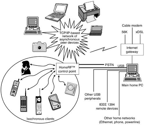
Due to the availability on a wide scale of the Microsoft Windows operating system and its use as a de facto standard for home PCs, the HomeRF working group has sought to streamline operation of SWAP-CA devices on these systems. In this section, we briefly describe how SWAP-CA devices operate in the context of a main-line operating system. A SWAP-CA node connected to a PC exposes three distinct types of interfaces: asynchronous data, isochronous data, and management. Figure 8.5 illustrates the three types of interfaces. The interface exposed to legacy data-centric applications and voice applications is a standard part of the Windows operating system. Information about the device not covered in the standard programming interface is exposed by a private interface that may be provided by the hardware vendors to application writers as needed.
Figure 8.5. Interfaces exposed by a SWAP-CA device
Windows defines a Network Device Interface Specification (NDIS) for programming networking hardware. The NDIS software library, which is the implementation of this specification, performs many of the functions that are common to device drivers of networking hardware, including synchronization, device mapping, interrupt handling, event logging, etc. Furthermore, it provides a standard interface for higher-level protocols and applications, which can be independent of the underlying hardware. Manufacturers of network adapters write a NDIS miniport driver that provides functionality specific to their hardware. Miniports of a given media type can be used by higher-level protocols knowledgable about that media type with no further modifications. Figure 8.6 illustrates how the various software modules fit together. The shaded blocks are provided as a standard part of the operating system and the miniport device drivers are supplied by the hardware vendor. Miniport drivers that are written to conform to the NDIS specification are guaranteed to work with the Windows operating system.
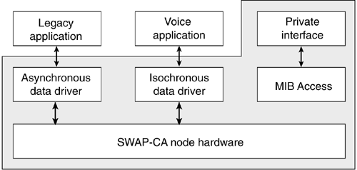
NDIS exports two distinct interfaces—a connectionless interface (used by broadcast media such as Ethernet) and a connection-oriented interface (used by media that have explicit connections between endpoints, such as in Asynchronous Transfer Mode network connections). Hardware manufacturers who produce A-node SWAP-CA devices are required to write a connectionless miniport device NDIS driver only that declares itself as a member of the Ethernet media type. To higher-level protocols and applications, SWAP-CA A-nodes are then indistinguishable from normal Ethernet adapters, allowing Ethernet-knowledgable applications to immediately function with SWAP-CA devices. This inheritance of applications was an important design goal. Hardware manufacturers who produce I-node devices create a miniport driver that declares itself as a member of the Ethernet media type and exposes a connection-oriented interface, not the connectionless interface traditionally used. In addition to the basic miniport functions, I-node drivers provide call management functions such as those required for setting up and terminating voice calls. Call control of SWAP-CA I-node adapters is managed by the Telephone Application Programming Interface (TAPI). TAPI is a simple, generic set of objects, interfaces, and methods for establishing connections between devices; TAPI communicates with NDIS via a TAPI service provider also called a TAPI proxy. TAPI applications set up, control, and tear down calls on SWAP-CA devices via the TAPI proxy. The various software modules are illustrated in Figure 8.7; once again the shaded regions are part of the operating system.
Figure 8.6. SWAP-CA A-node driver architecture

Some applications may wish to stream voice conversations between SWAP-CA adapters and another adapter within the PC in real time. An example scenario is that of a SWAP-CA I-node (a cordless phone) user communicating with a SWAP-CA connection point, which is part of the PC. This connection is forwarded on to another adapter in the PC, possibly a modem attached to a phone line or a sound card attached to speakers and a microphone. To implement this application, the voice data is streamed between the SWAP-CA adapters via the DirectShow Streaming module. The DirectX architecture was designed to accommodate real-time traffic within a PC. A DirectShow filter is plumbed from the data source (in this case, the SWAP-CA adapter) to the data sink (the modem or sound card). Voice streams coming in via NDIS are redirected to the Raw Channel Access (RCA) filter, which in turn sends them into DirectShow. The RCA filter is part of the operating system, so connection-oriented miniports are automatically voice stream-enabled.
Figure 8.7. SWAP-CA for isochronous service driver architecture
Positioning with Other Technologies
There are some wireless networking options that are either available today or will be available in the near future. Most have been designed for the enterprise market. Table 8.2 lists some of these options with a comparative overview of the HomeRF attributes to "similar" technologies. Comparisons are generally typically controversial. These technologies are really more complementary than competitive. IEEE 802.11 and HIPERLAN are effectively wireless Ethernet technologies developed for the enterprise network. Both support multiple "cell" hand-offs and roaming for coverage of entire campuses and together permit users to trade off data rate with cost and power consumption. Note that while HIPERLAN is legal in Europe only, similar technologies are likely in the recently created Unlicensed National Information Infrastructure (U-NII bands) located at 5.15-5.35 GHz and 5.725-5.825 GHz in the United States. The HomeRF and HomePNA technologies are very synergistic for home electronics manufacturers because they share much networking infrastructure even though the physical media are quite different. In both cases, these are simplified "single-cell" networks where voice to the PSTN and data to the Internet can be combined simultaneously. Finally, for in-room (or in-car) point-to-point or point-to-multipoint connectivity, the proposed Bluetooth protocol and the industry-proven IrDA standards (over 60 million units shipped) are most appropriate. Between these two technologies, Bluetooth offers far greater physical convenience in its usage model as it is not line-of-sight and can pass through minor obstructions. The IrDA standards are very hard to beat by any radio technology in terms of their data rate, cost, or physical size (but Bluetooth is getting closer than any protocol before it has).
Note that in Table 8.2, the standby current refers to the average current draw for the transceiver portion of portable devices while retaining full network availability for the given technology.
| Properties | HomeRF | Bluetooth | IEE 802.11 FH | HomePNA | IrDA | HIPERLAN |
|---|---|---|---|---|---|---|
| Operational spectrum | 2.404–2.478 GHz | 2.402–2.480 GHz | 2.40–2.4835 GHz | Phone line | Infrared | 51.15–5.3 GHz (& 17.1–17.3 GHz) |
| Physical layer | FHSS, 50 hops/sec, 2-FSK & 4-FSK | FHSS, 1600 hops/sec, GFSK | FHSS, 2-FSK, 4-FSK,… | ? | Optical | Differential GMSK |
| Channel access | CSMA/CA + TDMA | Master-slave, polling | CSMA/CA with RTS/ CTS | ? | Polling | EY-NPMA |
| Peak raw data rate | 0.8 & 1.6 Mbps | 0.721 Mbps | 1 & 2 Mbps | 10 Mbps | 16 Mbps (VFIR) | 23.5 Mbps |
| Range | <150 feet | <30 feet | <150 feet | Phone jack | ~3 feet | <90 feet |
| Standby & peak current | <1 mA & ~300 mA | <1 mA & ~60 mA | ~10 mA & ~400 mA | ? | <10 uA & ~300 mA | >2A |
| Data traffic | via TCP/IP | via PPP | via TCP/IP | via TCP/IP | via PPP | via TCP/IP |
| Voice traffic | via IP & PSTN | via IP & cellular | via IP | via IP & PSTN | via IP | via IP |
| Error robustness | CRC/ARQ Type 1 | 1/3 rate FEC, 2/3 rate FEC & ARQ Type 1 | CRC ARQ Type II | ? | ? | BCH (31,26) |
| Mobility support | NA | NA | Yes | NA | NA | Not specified |
| Energy conservation | Directory based | Yes | Directory based | No | No | Directory based |
| Guaranteed latency | <20 msec for voice | None | ? | ? | <10 msec for voice | |
| Speech coding | 32 Kbps ADPCM | 64 Kbps with CVSD/ logPCM | NA | ? | Not specified | 32 Kbps ADPCM |
| Security | 56-bit shared-key encryption | Stream cipher algorithm | 64-bit shared-key encryption | ? | ? | ? |
| Communications topology | Peer-to-peer, MS-to-BS | Master-slave | Peer-to-peer, MS-to-BS | ? | Master-slave | Peer-to-peer, multi-hop, MS-to-BS |
| Price point (estimate) | Medium | Medium | Medium/High | Medium/Low | Low | High |
HomeRF Products
Several companies are currently developing a range of end-user products that are based on the SWAP protocol. For instance, Proxim has recently announced that it will add SWAP 1.1 support into new members of its Symphony product family.
Proxim, Inc. is a leading supplier of 2.4 GHz wireless networking technology to both OEMs and end users worldwide. Details of other HomeRF-based products are shown in Table 8.3.
| Company Name | Product Description |
|---|---|
| Cayman | ADSL gateway |
| Compaq | Consumer desktop and mobile wireless products |
| Diablo Research | Consulting for HomeRF chip integration |
| IBM | Personal computing devices and peripherals |
| Intel | PC card/USB adapter/bridge products |
| LSI Logic | HomeRF ASIC |
| MobileStar | Hot-spot service for business travellers |
| Motorola | Multiuser wireless cable modem |
Furthermore, Siemens Communication Devices, a division of Siemens Information and Communication Products LLC, announced at CES 2000 that it will refine and deliver the voice communications element of the HomeRF networking specification.
With Siemens'addition of a voice component to home networks, consumers will enjoy greater convenience through wireless access to more voice, data, entertainment, and interactive services at affordable prices.
Future of HomeRF
The HomeRF organization is discussing a variety of future derivatives for the initial SWAP-CA specification. One possible derivative is simply to increase the data rate within the existing 2.4 GHz band while retaining full backward compatibility with the initial specification. The group is presently considering options in this regard that would scale SWAP-CA to 10 Mbps in the 2.4 GHz band.
In addition, HomeRF is also developing two major new market requirements documents. The first is SWAP-MM (for multimedia) which is looking at true video applications within the home enabled by wireless networking. This work will likely proceed to a formal technical proposal for the 5 GHz band. It is unclear at this point whether the SWAP-MM specification can ever be as near global as the 2.4 GHz SWAP-CA case. As with the SWAP-CA case, achieving consumer price points with a SWAP-MM solution will be critical. The other direction HomeRF is considering is an ultra-low-cost version called SWAP-lite that could be developed to be interoperable with future SWAP-CA devices while achieving much lower price and power consumption points. Keyboards, mouses, joysticks, remote controls, toys, etc. are the products that might use SWAP-lite. Clearly such a system overlaps in capability with infrared technology, which sets a tough measure to compete with in terms of price/ performance.