Example
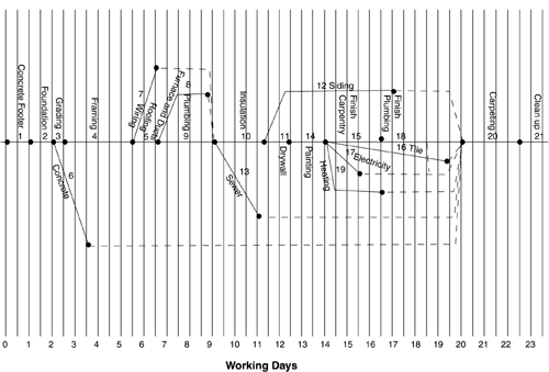
The project to be planned is to build a custom three-bedroom home according to specifications determined in a detailed set of architectural drawings. A good construction superintendent has reviewed these plans with the carpenter, mason, plumber, roofer, and construction foreman, and has listed tasks that need to be performed, their necessary sequence relationship, and the amount of time each task is expected to take (see Table 7-1). To be able to focus supervisory attention on tasks that are on the critical path, the superintendent laid out a critical path chart. This original rough charting and the final critical path chart are shown in Figures 7-4 and 7-5.
Figure 7-4.

Figure 7-5.

| Task | Necessary Preceding Task(s) | Time Required Estimate in Days |
|---|---|---|
| 1. Concrete Footer | 1 | |
| 2. Foundation | #1 | 1 |
| 3. Grading | #2 | .5 |
| 4. Framing | #3 | 2.6 |
| 5. Roofing | #4 | 1 |
| 6. Concrete Basement Floor | #2 | 1 |
| 7. Wiring | #4 | 1 |
| 8. Furnace & Ducts | #5 | 2.25 |
| 9. Plumbing | #5 | 2.5 |
| 10. Insulation | #7,8,9 | 2.25 |
| 11. Dry Wall | #10 | 1 |
| 12. Siding | #10 | 5.5 |
| 13. Sewer Lines | #9 | 2 |
| 14. Painting | #11 | 1.5 |
| 15. Finish Carpentry | #14 | 2.5 |
| 16. Tile | #14 | 5 |
| 17. Electrical Trim | #14 | 1.5 |
| 18. Finish Plumbing | #15 | 3.5 |
| 19. Heating Trim | #14 | 2.5 |
| 20. Carpeting | #6, 12, 13, 16, 17, 18, 19 | 2 |
| 21. Clean up | #20 | 2 |
The shaded line on the first draft chart represents the critical path. The construction superintendent chose to lay out the “concrete footer” and “foundation” tasks horizontally. When these tasks are completed, both “grading” and “concrete” then can begin.
“Grading” is laid out horizontally and “concrete” angles upward. Continuing like this, “framing” and “roofing” are laid out horizontally and “wiring” is laid out angled upward. Once the tasks of “roofing is completed, “furnace and ducts” and “plumbing” then can be started.
When laying out the critical path, you should either angle each of several Day 1 start tasks up or down, or start them at different vertical points on the Day 0 line.
The superintendent can redraw the chart, which becomes the second critical path chart draft. He or she shows each critical path task laid out horizontally. The slack, depicted by dots, is very easy to see on this chart. (These dots connect necessary predecessors to their successors, when another predecessor takes more time.)
Slack is selectively utilized to make the most efficient use of the resources. It may be advantageous, for example, to delay starting the wiring task by one day. This might be doable without delaying the overall project. The superintendent will not agree to use up all the slack on one task unless there is a serious necessity. Remember, using up the entire slack for a task makes the task critical.
We find the critical path arrow diagram extremely useful during a project's execution. We each prepare one for every project we lead, particularly the large ones.
Figure 7-2A and B show a Gantt chart representation of the “Build a House Project” using Microsoft Project 2002®. In these figures, the critical path tasks are represented with solid bars. Non-critical path tasks are shown with shaded bars.
