Learning the Bridge Pattern: An Example
To learn the thinking behind the Bridge pattern and what it is trying to do, I will work through an example from scratch. Starting with requirements, I will derive the pattern and then see how to apply it.
Perhaps this example will seem basic. But look at the concepts discussed in this example and then try to think of situations that you have encountered that are similar, having
Variations in abstractions of a concept, and
Variations in how these concepts are implemented.
You will see that this example has many similarities to the CAD/CAM problem discussed earlier. But rather than give you all the requirements up front, I am going to give them a little at a time, just as they were given to me. You can't always see the variations at the beginning of the problem.
Bottom line: During requirements definition, explore for variations early and often!
Suppose I have been given the task of writing a program that will draw rectangles with either of two drawing programs. I have been told that when I instantiate a rectangle, I will know whether I should use drawing program 1 (DP1) or drawing program 2 (DP2).
The rectangles are defined as two pairs of points, as represented in Figure 9-1. The differences between the drawing programs are summarized in Table 9-1.
Figure 9-1. Positioning the rectangle.

| DP1 | DP2 | |
|---|---|---|
| Used to draw a line | draw_a_line( x1, y1, x2, y2) | drawline( x1, x2, y1, y2) |
| Used to draw a circle | draw_a_circle( x, y, r) | drawcircle( x, y, r) |
My customer told me that the collection (the client of the rectangles) does not want to worry about what type of drawing program it should use. It occurs to me that since the rectangles are told what drawing program to use when instantiated, I can have two different kinds of rectangle objects: one that uses DP1 and one that uses DP2. Each would have a draw method but would implement it differently. I show this in Figure 9-2.
Figure 9-2. Design for rectangles and drawing programs (DP1 and DP2).

By having an abstract class Rectangle, I take advantage of the fact that the only difference between the different types of Rectangles are how they implement the drawLine method. The V1Rectangle is implemented by having a reference to a DP1 object and using that object's draw_a_line method. The V2Rectangle is implemented by having a reference to a DP2 object and using that object's drawline method. However, by instantiating the right type of Rectangle, I no longer have to worry about this difference.
Example 9-1. Java Code Fragments
class Rectangle {
  public void draw () {
     drawLine(_x1,_y1,_x2,_y1);
     drawLine(_x2,_y1,_x2,_y2);
     drawLine(_x2,_y2,_x1,_y2);
     drawLine(_x1,_y2,_x1,_y1);
   }
  abstract protected void
    drawLine ( double x1, double y1,
               double x2, double y2);
}

class V1Rectangle extends Rectangle {
  drawLine( double x1, double y1,
            double x2, double y2) {
    DP1.draw_a_line( x1,y1,x2,y2);
  }
}
class V2Rectangle extends Rectangle {
  drawLine( double x1, double y1,
            double x2, double y2) {
    // arguments are different in DP2
    // and must be rearranged
    DP2.drawline( x1,x2,y1,y2);
  }
}
|
Now, suppose that after completing this code, one of the inevitable three (death, taxes, and changing requirements) comes my way. I am asked to support another kind of shape—this time, a circle. However, I am also given the mandate that the collection object does not want to know the difference between Rectangles and Circles.
It occurs to me that I can simply extend the approach I've already started by adding another level to my class hierarchy. I only need to add a new class, called Shape, from which I will derive the Rectangle and Circle classes. This way, the Client object can just refer to Shape objects without worrying about what kind of Shape it has been given.
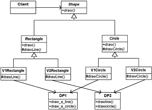
As a beginning object-oriented analyst, it might seem natural to implement these requirements using only inheritance. For example, I could start out with something like Figure 9-2, and then, for each kind of Shape, implement the shape with each drawing program, deriving a version of DP1 and a version of DP2 for Rectangle and deriving a version of DP1 and a version of DP2 one for Circle. I would end up with Figure 9-3.
Figure 9-3. A straightforward approach: implementing two shapes and two drawing programs.

I implement the Circle class the same way that I implemented the Rectangle class. However, this time, I implement draw by using drawCircle instead of drawLine.
Example 9-2. Java Code Fragments
abstract class Shape {
  abstract public void draw ();
}
abstract class Rectangle extends Shape {
  public void draw () {
    drawLine(_x1,_y1,_x2,_y1);
    drawLine(_x2,_y1,_x2,_y2);
    drawLine(_x2,_y2,_x1,_y2);
    drawLine(_x1,_y2,_x1,_y1);
  }
  abstract protected void
    drawLine(
      double x1, double y1,
      double x2, double y2);
}
class V1Rectangle extends Rectangle {
  protected void drawLine (
    double x1, double y1,
    double x2, double y2) {
      DP1.draw_a_line( x1,y1,x2,y2);
  }
}
class V2Rectangle extends Rectangle {
  protected void drawLine (
    double x1, double x2,
    double y1, double y2) {
    DP2.drawline( x1,x2,y1,y2);
  }
}
abstract class Circle extends Shape {
  public void draw () {
    drawCircle( x,y,r);
  }
  abstract protected void
    drawCircle (
      double x, double y, double r);
}
class V1Circle extends Circle {
  protected void drawCircle() {
    DP1.draw_a_circle( x,y,r);
  }
}
class V2Circle extends Circle {
  protected void drawCircle() {
    DP2.drawcircle( x,y,r);
  }
}
|
To understand this design, let's walk through an example. Consider what the draw method of a V1Rectangle does.
Rectangle's draw method is the same as before (calling drawLine four times as needed).
drawLine is implemented by calling DP1's draw_a_line.
In action, this looks like Figure 9-4.
Figure 9-4. Sequence Diagram when have a V1Rectangle.

Reading a Sequence Diagram.As I discussed in Chapter 2, “The UML—The Unified Modeling Language,” the diagram in Figure 9-4 is a special kind of interaction diagram called a Sequence Diagram. It is a common diagram in the UML. Its purpose is to show the interaction of objects in the system.
You read the diagram from the top down. Each numbered statement is a message sent from one object to either itself or to another object.
|
Even though the Class Diagram makes it look like there are many objects, in reality, I am only dealing with three objects (see Figure 9-5):
Figure 9-5. The objects present.

The client using the rectangle
The V1Rectangle object
The DP1 drawing program
When the client object sends a message to the V1Rectangle object (called myRectangle) to perform draw, it calls Rectangle's draw method resulting in steps 2 through 9.
Unfortunately, this approach introduces new problems. Look at Figure 9-3 and pay attention to the third row of classes. Consider the following:
The classes in this row represent the four specific types of Shapes that I have.
What happens if I get another drawing program, that is, another variation in implementation? I will have six different kinds of Shapes (two Shape concepts times three drawing programs).
Imagine what happens if I then get another type of Shape, another variation in concept. I will have nine different types of Shapes (three Shape concepts times three drawing programs).
The class explosion problem arises because in this solution, the abstraction (the kinds of Shapes) and the implementation (the drawing programs) are tightly coupled. Each type of shape must know what type of drawing program it is using. I need a way to separate the variations in abstraction from the variations in implementation so that the number of classes only grows linearly (see Figure 9-6).
Figure 9-6. The Bridge pattern separates variations in abstraction and implementation.

This is exactly the intent of the Bridge pattern: [to] de-couple an abstraction from its implementation so that the two can vary independently.[2]
[2] Gamma, E., Helm, R., Johnson, R., Vlissides, J., Design Patterns: Elements of Reusable Object-Oriented Software, Reading, Mass.: Addison-Wesley, 1995, p. 151.
Before showing a solution and deriving the Bridge pattern, I want to mention a few other problems (beyond the combinatorial explosion).
Looking at Figure 9-3, ask yourself what else is poor about this design.
Does there appear to be redundancy?
Would you say things have high cohesion or low cohesion?
Are things tightly or loosely coupled?
Would you want to have to maintain this code?
The overuse of inheritance.As a beginning object-oriented analyst, I had a tendency to solve the kind of problem I have seen here by using special cases, taking advantage of inheritance. I loved the idea of inheritance because it seemed new and powerful. I used it whenever I could. This seems to be normal for many beginning analysts, but it is naive: given this new “hammer,” everything seems like a nail. Unfortunately, many approaches to teaching object-oriented design focus on data abstraction—making designs overly based on the “is-ness” of the objects. As I became an experienced object-oriented designer, I was still stuck in the paradigm of designing based on inheritance—that is, looking at the characteristics of my classes based on their “is-ness.” Characteristics of objects should be based on their responsibilities, not on what they might contain or be. Objects, of course, may be responsible for giving information about themselves; for example, a customer object may need to be able to tell you its name. Think about objects in terms of their responsibilities, not in terms of their structure. Experienced object-oriented analysts have learned to use inheritance selectively to realize its power. Using design patterns will help you move along this learning curve more quickly. It involves a transition from using a different specialization for each variation (inheritance) to moving these variations into used or owned objects (composition). |
When I first looked at these problems, I thought that part of the difficulty might have been that I simply was using the wrong kind of inheritance hierarchy. Therefore, I tried the alternate hierarchy shown in Figure 9-7.
Figure 9-7. An alternative implementation.

I still have the same four classes representing all of my possible combinations. However, by first deriving versions for the different drawing programs, I eliminated the redundancy between the DP1 and DP2 packages.
Unfortunately, I am unable to eliminate the redundancy between the two types of Rectangles and the two types of Circles, each pair of which has the same draw method.
In any event, the class explosion that was present before is still present here.
The sequence diagram for this solution is shown in Figure 9-8.
Figure 9-8. Sequence Diagram for new approach.

While this may be an improvement over the original solution, it still has a problem with scaling. It also still has some of the original cohesion and coupling problems.
Bottom line: I do not want to have to maintain this version either! There must be a better way.
Look for alternatives in initial design.Although my alternative design here was not significantly better than my original design, it is worth pointing out that finding alternatives to an original design is a good practice. Too many developers take what they first come up with and go with that. I am not endorsing an in-depth study of all possible alternatives (another way of getting “paralysis by analysis”). However, stepping back and looking at how we can overcome the design deficiencies in our original design is a great practice. In fact, it was just this stepping back, a refusal to move forward with a known, poor design, that led me to understanding the powerful methods of using design patterns that this entire book is about. |
