
Unlike filters or generators, motion properties are already present on every clip. You can access them by loading a clip or sequence into the Viewer and then selecting the Motion tab.
A few of the controls you find on the Motion tab, such as Opacity, Crop, Distort, and Drop Shadow, don’t have any obvious connection to movement.
The first part of this chapter introduces motion properties as static image modification tools that can be used in either static or animated compositions. The second part of the chapter, “Animating Clip Motion with Keyframes,” discusses motion paths: the time-based uses of motion properties.
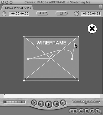
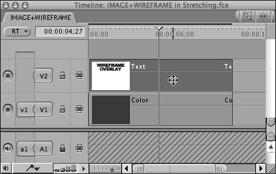
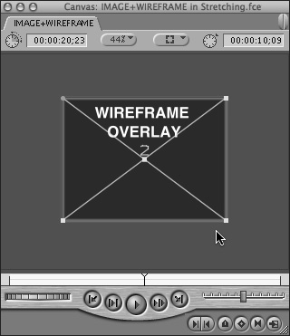
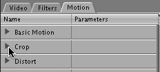
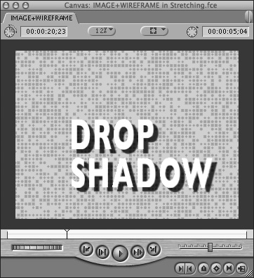
The motion properties listed here are present automatically on every clip, and their controls can be adjusted on the clip’s Motion tab in the Viewer (Figure 15.1) or on the clip’s Image + Wireframe mode overlay in the Canvas (Figure 15.2).
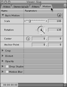
Scale: Adjusts the size of the clip to make it smaller or larger than the sequence frame size.
Rotation: Rotates the clip around its anchor point without changing its shape.
Center: The x,y coordinates specify the center point of the clip.
Anchor Point: The x,y coordinates specify another point relative to the clip’s center point to use as a pivot point for rotating, scaling, or animating the motion path of the clip.
Crop: Crops (removes) a portion of the clip from the side you specify.
Distort: Changes the shape of the clip by adjusting its corners. The Aspect Ratio parameter sets the clip’s height:width proportions.
Opacity: Makes a clip opaque or translucent; 100 percent is completely opaque, and 0 percent is completely transparent.
Drop Shadow: Places a drop shadow behind the selected clip, with a color, softness, and opacity you specify.
Motion Blur: Blurs moving images by a specified percentage, by combining the images of adjacent frames to create the effect.
Final Cut Express uses x,y coordinates to specify a clip’s position in the frame. For example, in the DV-NTSC frame size (720 by 480 pixels), you can specify locations outside the visible frame by using coordinate values greater than plus or minus 360 on the x axis, or plus or minus 240 on the y axis. You’ll often see x,y coordinates specified like this: (50,25). The first number (50) is the x coordinate; the second number (25) is the y coordinate. Figure 15.3 illustrates x,y coordinate locations in a DV-NTSC frame (720 by 480 pixels).
Motion Properties Modify an Image or Make It Move
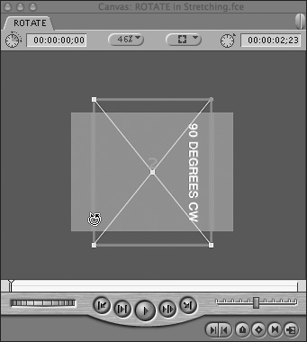
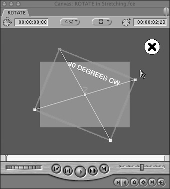
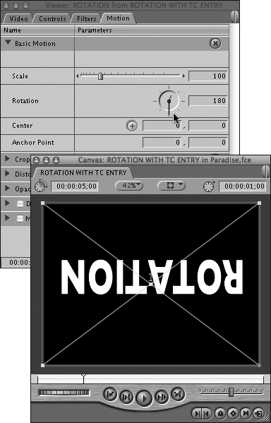
Motion properties perform basic image modifications when used as static composition tools, but they can also create motion effects when you adjust their values over time. For example, you might use the Rotation control as a static composition tool to display a title at a 90-degree angle (Figure 15.4) or animate rotation by setting incrementally increasing values over time (Figure 15.5).
Enabling Image+Wireframe mode in the Canvas or the Viewer activates a wireframe overlay that appears on your clip image. You must be in Image+Wireframe mode to graphically manipulate a clip’s motion properties in the Canvas or the Viewer.
The elements of the wireframe aren’t just indicators; they’re also controls you can use to manipulate the size, shape, and position of your clip’s image. Select the appropriate tool from the Tool palette; then drag a handle on the clip’s wireframe. Figure 15.6 offers a key to wireframe handles and tools.
Figure 15.6. To manipulate motion properties in Image+Wireframe mode, select a tool; then drag the appropriate handle on the clip’s wireframe.
Tip
While you work in Image+Wireframe mode, note that the selected track’s number appears just above the clip’s center point. The track number helps you remember which layer you’ve selected. If you’re working on an effects sequence with many layered elements, that’s a big help.
Wireframe mode uses green highlighting to indicate whether a keyframe is present on a frame and what type of keyframe it is (Figure 15.7).
To enable Wireframe mode:
Do one of the following:
Press W once to place the Viewer or the Canvas in Image+Wireframe mode. (Press W again to return to Image mode.)
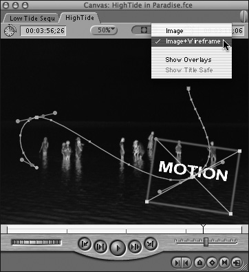
Choose Image+Wireframe from the View pop-up menu at the top of the Viewer or the Canvas (Figure 15.8).
Choose View > Image+Wireframe.
In Final Cut Express, when you want to make a clip’s image larger or smaller, tilted or skewed, opaque or transparent, you adjust the clip’s motion properties—even if the clip’s not moving. Not very intuitive, is it?
As long as you’re not animating the clip (changing the size and shape of the clip’s image over time), you don’t need to add any motion keyframes. Simply open the clip and adjust the clip’s default motion properties settings. FCE offers two ways to modify a clip’s motion properties: by adjusting the controls and entering numerical values on the clip’s Motion tab in the Viewer, or by using the Tool palette’s image modification tools to manipulate the clip’s image directly in the Canvas wireframe overlay. When you’re going for precision and consistency, you’ll probably end up working both numerically and graphically.
All operations described in this section can be performed in both places. Start each operation by following the general setup procedure for each respective mode; the setup tasks are described in the sections that follow.
To set up for motion properties adjustment in the Canvas Wireframe mode:
In the Timeline, select the clip you want to reposition (Figure 15.9). If you are working with a layered composition, be sure to choose the layer you want to affect.
From the Tool palette, choose the appropriate image modification tool for the motion property you want to adjust. Refer to the key to wireframe handles and tools in Figure 15.6.
If the Canvas’s Image+Wireframe mode is not already activated, press W to turn it on.
The outline of the wireframe overlay appears on the selected clip’s image (Figure 15.10).
To set up for motion properties adjustment on the Viewer’s Motion tab:
Double-click the clip in the Timeline or the Browser to open it in the Viewer.
In the Viewer, click the Motion tab.
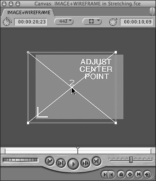
Clips start out positioned at the center of the Canvas or the Viewer. You can reposition a clip’s center point by dragging it to a new position in the Canvas or in the Viewer, or you can specify new center point coordinates on the clip’s Motion tab. You can position a clip partially or completely outside the sequence frame.
To adjust a clip’s center point using Wireframe mode:
Follow the setup steps for Wireframe mode presented earlier; then click anywhere inside the clip’s image and drag it to a new position (Figure 15.11).
To adjust a clip’s center point on the Viewer’s Motion tab:
Follow the setup steps for the Motion tab mode described earlier; then do one of the following:
Enter new x,y coordinates for the clip’s center location. Enter the x coordinate in the left value field and the y coordinate in the right value field.
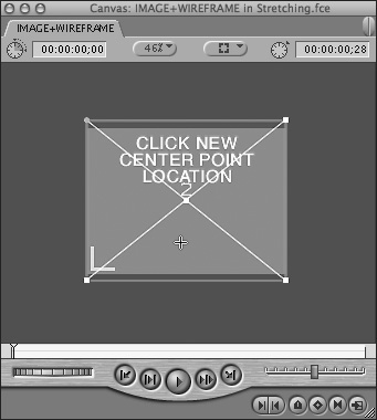
Click the Point Select (+) button (Figure 15.12) (located to the left of the Center value field) and then specify new center coordinates by clicking the new center location in the Canvas (Figure 15.13) or on the Video tab of the Viewer.
A clip placed in a Final Cut Express sequence plays at the same frame size at which it was captured, regardless of the sequence frame size. A clip whose native size is smaller than the sequence frame size appears in the center of the sequence frame; a clip whose native size is larger than the sequence frame size shows only the portion of the clip that fits inside the sequence frame dimensions.
You can adjust the scale of a clip to change its frame size (for the current sequence only). If you want to create a media file of your clip at a different size that does not need to be rendered before it can be played back, you should export a copy of the clip at the frame size you need.
To scale a clip in Wireframe mode:
Follow the setup steps for Wireframe mode presented earlier.
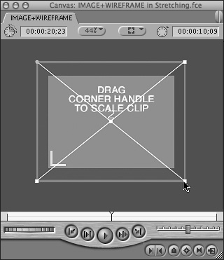
Drag a corner handle to scale a clip while maintaining its proportions (Figure 15.14).
Tips
Smooth your keyframes with Bézier curves when you animate scale. Curve type keyframes produce a change in the rate of scale at the beginning and the end of the scaling animation, making the movement less mechanical. To learn how to convert a keyframe to a Bézier curve type, see “To refine a motion keyframe” later in this chapter.
When you’re scaling a clip, it’s easy to drift away from the clip’s original aspect ratio, but not easy to find the control that resets your clip to its native proportions. Go to the clip’s Motion tab and scroll down to the Distort controls. That’s where you’ll find the Aspect Ratio parameter. Reset the value to 0, and you’ll restore height:width sanity to your scaled clip.
To scale a clip on the Viewer’s Motion tab:
Follow the setup steps for Motion tab mode presented earlier; then do one of the following:
Adjust the Scale slider (Figure 15.15).
Enter a percentage in the text field located to the right of the slider; 100 percent is equal to the clip’s native size.
Rotation is an important part of modern video effects (as you know if you’ve watched a TV commercial break recently).
A clip rotates around its anchor point. The default anchor point location matches the clip’s center point, but you can rotate a clip around a different pivot point by changing the location of the anchor point. You can position a clip at the edge of your sequence frame and rotate your clip partially or completely outside the Canvas, so it appears on the screen for only a portion of its rotation. You can also rotate a clip up to 24 revolutions in either direction or use the Rotation control to angle a clip as part of a static composition.
To adjust a clip’s rotation angle in Wireframe mode:
Follow the setup steps for Image+Wireframe mode presented earlier; then do one of the following:
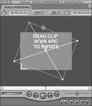
Click an edge of the border and drag in an arc around the clip’s center point (Figure 15.16).
Click a border edge and then drag farther away from the clip’s center point to get more precise control over the rotation.
Hold down the Shift key while dragging to constrain the rotation positions to 45-degree increments.
Drag around the clip multiple times without releasing the mouse to specify a number of rotations.
To adjust a clip’s rotation angle on the Viewer’s Motion tab:
Follow the setup steps for the Motion tab mode described earlier; then do one of the following:
Drag the black rotation needle around the dial to set a rotation position (Figure 15.17); the red needle indicates the number of complete revolutions.
Enter a new value in the text box.
The clip realigns at the new rotation angle for the selected frame.
Tip
To create an animated rotation effect on the Motion tab, you must set individual keyframes for each rotation angle value (see “Animating Clip Motion with Keyframes” later in this chapter).
You can crop a clip either by dragging with the Crop tool or by specifying the number of pixels to crop from the borders. Use the Edge Feather option to create a soft border at the crop line.
When you use the Crop tool to remove part of a clip’s image, the selected parts are hidden, not deleted. You can restore the cropped sections to view by clicking the Reset button next to the Crop controls on the Viewer’s Motion tab.
To crop a clip in Wireframe mode:
Follow the setup steps for the Image+Wireframe mode presented earlier; then select the Crop tool from the Tool palette.
Do one of the following:
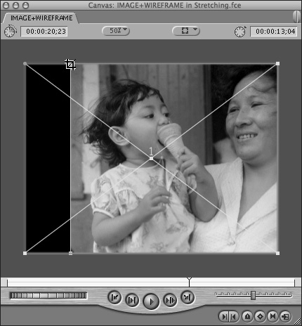
Drag from the edges of the clip to hide elements in the image (Figure 15.18).
Shift-drag to constrain the clip’s aspect ratio as you crop.
Command-drag to trim both horizontal edges or both vertical edges simultaneously.
Use Option in combination with Shift and Command to force rendering while you perform a crop operation.
To crop a clip on the Motion tab:
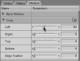
Follow the setup steps for the Motion tab mode described earlier; then open the Crop control bar by clicking the expansion triangle on the left (Figure 15.19).
To crop the clip from a specific side, do one of the following:
Drag the slider for that edge to a new value (Figure 15.20).
Enter a new value in the corresponding text field.
To soften the cropped edges of the clip, do one of the following:
Adjust the Edge Feather slider to specify the width of the feathered edge.
Specify a value in the Edge Feather text field.
Use the Distort tool to make independent adjustments to each corner point of a clip’s wireframe, or use the Viewer’s Motion tab to numerically specify x,y coordinates for the location of each corner point.
To distort the shape of a clip in Wireframe mode:
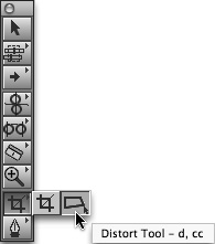
Follow the setup steps for the Wireframe mode presented earlier; then select the Distort tool from the Tool palette (Figure 15.21).
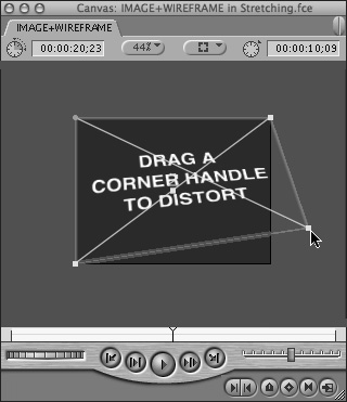
To distort the clip’s image, do one of the following:
Drag a corner handle of the clip’s wireframe (Figure 15.22).
Shift-drag to change the perspective of the image.
To distort a clip on the Viewer’s Motion tab:
Follow the setup steps for the Motion tab mode presented earlier; then open the Distort control bar by clicking the expansion triangle.
To specify new locations for the corner points, do one of the following:
Enter new values for the corner points you want to move.
Adjust the Aspect Ratio parameter to change the clip’s height:width ratio, relocating all four corner points. A clip’s original aspect ratio has a value of zero.
Final Cut Express clips start out 100 percent opaque (Figure 15.23). If you superimpose a clip over another clip in the base track of your sequence, the background image will be completely hidden until you adjust the opacity of the superimposed clip to less than 100 percent, making it semitransparent (Figure 15.24).
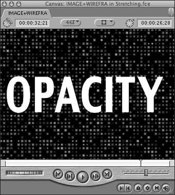
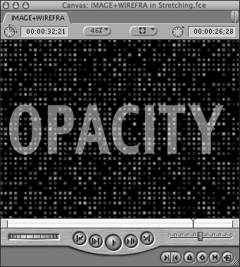
Figure 15.24. The superimposed title with opacity set to less than 100 percent appears semitransparent.
Layering multiple, semitransparent images is a basic compositing technique, and one you may be familiar with if you have ever worked with Adobe Photoshop.
You can adjust a clip’s opacity on the Viewer’s Motion tab or with the opacity clip overlay in the Timeline.
To set a clip’s opacity on the Viewer’s Motion tab:
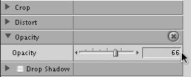
Follow the setup steps for the Motion tab mode described earlier; then open the Opacity control bar by clicking the triangle.
To set the opacity level, do one of the following:
Use the slider control.
Enter a value between 0 and 100 in the Opacity text field (Figure 15.25).
A clip’s opacity can be adjusted directly in the Timeline using the clip overlay for opacity, a level line graph that appears over the clip icon in the Timeline. To display clip overlays, click the Clip Overlays control in the lower-left corner of the Timeline.
For information on adjusting clip overlays in the Timeline, see “Working with Keyframes in the Timeline” in Chapter 14.
Use the Modify > Levels command to adjust opacity levels for a group of Timeline clips in a single operation.
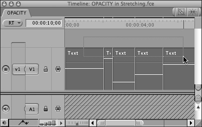
To adjust opacity levels on a group of clips:
In the Timeline, select a group of clips whose levels you want to adjust (Figure 15.26).
Choose Modify > Levels.
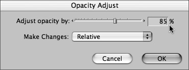
In the Opacity Adjust dialog box, do one of the following:
Choose Relative from the pop-up menu. Adjust each clip’s opacity relative to its current level by specifying a percentage value (Figure 15.27).
Choose Absolute from the pop-up menu; then set an absolute value for all clips’ opacity by specifying a percentage value.
Click OK.
Drop shadows add the illusion of dimensional depth to the 2D television screen (Figure 15.28). Titles pop out from the backgrounds, or clips softly float over other clips; complex silhouettes can add a special depth to your sequences. You can add a drop shadow to any clip whose display size is smaller than the sequence frame size.
You can apply drop shadows to clips that were captured at a smaller frame size and to clips that have been scaled, cropped, moved, or distorted. You can also add a drop shadow to a full-size clip with an alpha channel.
To add a drop shadow to a clip:
Double-click the clip in the Timeline or the Browser to open it in the Viewer.
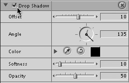
In the Viewer, click the Motion tab; then check the Drop Shadow check box (Figure 15.29).
To adjust your drop shadow settings, do any of the following:
Enter Offset settings to specify the shadow’s distance from the clip.
Enter Angle settings to specify the position of the shadow relative to the clip edge.
Enter Softness settings to specify the degree of blending in the shadow’s edge.
Enter Opacity settings to specify the shadow’s degree of transparency.
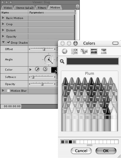
In the Color control bar, click the expansion triangle; then pick a color by doing one of the following:
Drag the hue, saturation, and brightness sliders to new values.
Enter numeric color values in the text fields.
Click the eyedropper and click in the Canvas to sample a color.
Click the color swatch and use one of the color pickers to choose the desired color (Figure 15.30).
The motion blur effect enhances the illusion of movement by compositing the images of adjacent frames (Figure 15.31). This is definitely one control to experiment with, particularly for creating interesting, animated, soft-focus background textures. If you’re using graphics or stills, you must combine motion blur with other motion effects—scaling, rotation, or motion paths, for example—to see the motion blur effect, but you can use it to create a lot of action in your composition, even with static elements (Figure 15.32).
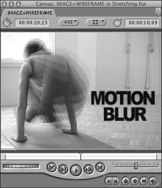
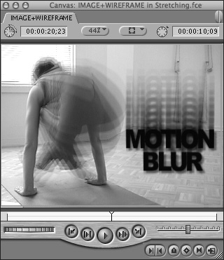
Figure 15.32. You can apply motion blur to a static graphic as well, but you must animate the graphic with a motion path first.
Tip
Nest a clip containing an element you want to blur. By increasing the frame size when you nest, you can create a roomier bounding box that will accommodate the larger size of your blurred element.
To add motion blur to a clip:
Double-click the clip in the Timeline or the Browser to open it in the Viewer.
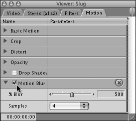
In the Viewer, click the Motion tab; then check the Motion Blur check box near the bottom of the tab (Figure 15.33).
Click the Motion Blur expansion triangle to reveal the controls for blurring motion.
Use the % Blur slider or enter a value in the text field. Values range from 1000%, which blurs a frame’s image across 10 frames, to 100%, which blurs the image on a single frame.
To change the quality of the motion blur, adjust the sample rate by choosing a value from the Samples pop-up menu (Figure 15.34).
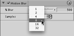
Figure 15.34. Specify a number of samples by selecting a value from the Samples pop-up menu. The sample rate changes the quality of the motion blur. Fewer samples creates more visible intermediate steps.
The sample rate is the number of in-between images FCE calculates when it compares two adjacent frames to calculate motion blur. A low sample rate produces more visible intermediate steps; a high sample rate produces a smoother look but takes longer to render.
The previous section explained how to use motion properties to alter a clip’s shape, size, and transparency in a static composition. In this section, you’ll finally learn how to use motion properties to actually move clips around.
The best place to use motion keyframes to animate a motion path is either the Canvas or the Viewer when it is in Image+Wireframe mode—all the operations described in this section are performed in Wireframe mode.
You can work with motion keyframes in both the Canvas and the Viewer, but because keyframing more commonly happens in the Canvas, the directions in this section mention only the Canvas.
To set a motion keyframe:
In the Canvas, position the playhead at the frame where you want to set the keyframe.
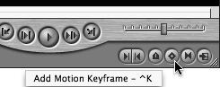
Click the Add Motion Keyframe button (Figure 15.35); or press Control-K.
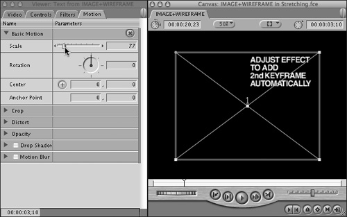
To set an additional keyframe, move the playhead to the next location where you want to set a keyframe; then do one of the following:
Add another keyframe; then adjust the Motion tab parameter control or make a graphical adjustment to the clip’s wireframe.
Make an adjustment to a Motion tab parameter control or make a graphical adjustment to the clip’s wireframe.
Final Cut Express adjusts the values and then automatically adds the keyframe (Figure 15.36).
Tip
Clicking the Add Motion Keyframe button in the Canvas sets a motion keyframe across all motion parameters for the current frame.
To navigate between motion keyframes:
Press Shift-K to move to the next motion keyframe.
Press Option-K to move to the previous keyframe.
The playhead moves to the next keyframe in the appropriate direction, and the Canvas updates to show the new position of the clip.
Tip
Toggle the Auto Select control off for any track you want to exclude from your keyframe review. FCE will ignore the keyframes on that track.
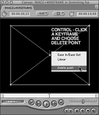
To delete a motion keyframe:
In the Canvas wireframe overlay, do one of the following:
Control-click the keyframe and choose Delete Point from the shortcut menu (Figure 15.37).
Option-click the keyframe with the Selection tool or the Pen tool (Figure 15.38).
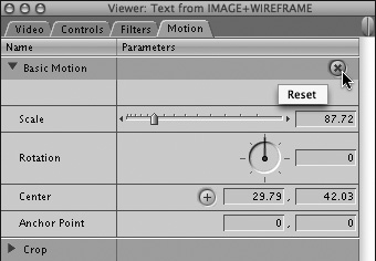
To delete all keyframes:
On the clip’s Motion tab, click the Reset button to delete all keyframes for that parameter and return the parameter to its original setting (Figure 15.39).
Control-click the keyframe and choose Ease In/Ease Out from the shortcut menu (Figure 15.40).
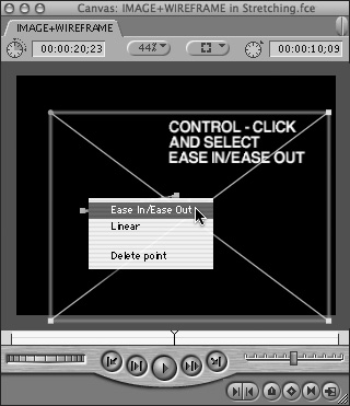
Figure 15.40. To smooth a corner type keyframe to a Bézier curve type, Control-click the keyframe and choose Ease In/Ease Out from the shortcut menu.
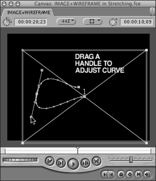
The keyframe changes into a curve type, and Bézier handles appear.
Drag the small blue circle at the end of the Bézier handle to adjust the motion path leading up to (or away from) the keyframe (Figure 15.41).
Tip
Refine opacity and audio level overlay keyframes in the Timeline by Control-clicking the overlay keyframe and selecting Smooth from the shortcut menu.
To move a motion keyframe:
In the Canvas wireframe overlay, click the motion keyframe with the appropriate selection tool and drag it to a new location.
Evenly spaced keyframes are essential for smooth, even changes in your effects and for precision synchronization to music or other effects. This is especially true for motion effects. When you animate a program element, using timecode ensures that your keyframes will be set at precise intervals. This task shows you how to rotate a clip using timecode entry to set keyframes.
To set keyframes using timecode entry:
In the Timeline, double-click the clip you want to rotate to open it in the Viewer.
In the Viewer, click the Motion tab; then press the Home key to jump the playhead to the first frame of your clip.
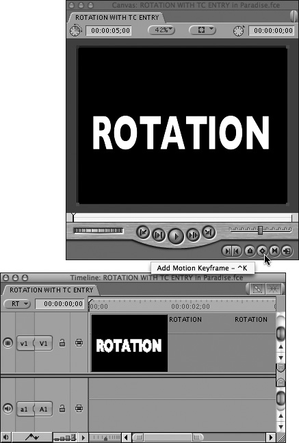
In the Canvas, click the Add Keyframe button (Figure 15.42); or press Control-K.
The clip’s first Rotation keyframe is set on the first frame.
Verify that the Rotation control is set to zero.
This establishes the clip’s orientation at the beginning of the rotation.
Click the Current Timecode field at the bottom left of the Motion tab; then type +30 to move the playhead 30 frames forward (Figure 15.43).
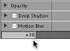
Figure 15.43. Click the Current Timecode field at the bottom left of the Motion tab; then type +30 to add 30 frames to the playhead location.
The playhead advances 30 frames.
Click the Add Keyframe button again; then do one of the following:
In the Rotation control dial, drag the needle clockwise to set the keyframe value to 180 (Figure 15.44).
Enter 180 in the Rotation text field.
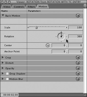
Repeat steps 5 and 6, increasing the Rotation value to 360.
You have set three keyframes, exactly 30 frames apart, causing your clip to complete one full 360-degree rotation in 2 seconds (Figure 15.45).
Press Option-K to step backward through your three keyframes, noting that the clip flips and the Rotation value updates at each keyframe. Press Shift-K to step forward through the keyframes.
You must render your rotating clip before you can play it back. Select the clip; then choose Sequence > Render Selection.
Play back your rotation effect.
Tip
Strictly speaking, it’s not necessary to click the Add Keyframe button to set the second and third keyframes; you need only change the keyframe’s value on the Motion tab. However, rotation keyframes don’t show up in the wireframe overlay even when they are present. Pressing the Add Keyframe button sets a keyframe across all motion parameters, so the green highlighting is visible.
If you are new to motion paths, try one—if your FCE system is powerful enough to support real-time previewing, you can play back a moving clip without rendering, and you will get a feel for how the Canvas function changes when you are working in Image+Wireframe mode. You can work in Image+Wireframe mode in the Viewer as well.
When you animate the center point, you move the whole clip. The following section explains the basic steps for animating a simple motion path.
Tip
Motion paths are limited to single sequence clips; you must nest sequence clips if you want to create a motion path that includes two or more clips that have been edited together. For more information on nesting items, see Chapter 4, “Projects, Sequences, and Clips.”
To create a motion path in the Canvas:
In the Timeline, select a sequence clip; then position the playhead on the first frame in your clip.
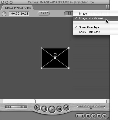
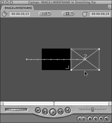
Make the Canvas active; then choose 12% from the Zoom pop-up menu and Image+Wireframe from the View pop-up menu (Figure 15.46).
To add the first keyframe, click the Add Motion Keyframe button in the Canvas.
Final Cut Express sets the first keyframe across all motion parameters for that sequence frame.
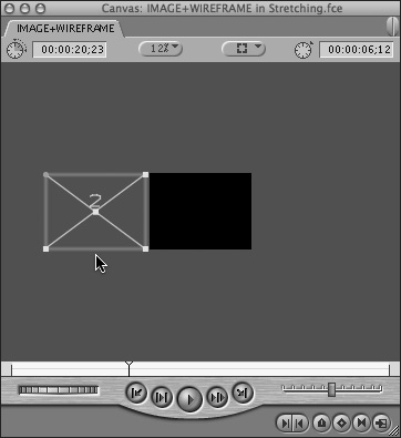
In the Canvas, drag the wireframe’s center handle to the left until the right side of the wireframe aligns with the left edge of the black background. Hold down the Shift key while you drag to constrain the motion path. This makes it easier to drag in a straight line.
Your clip is now positioned just off the screen, at the left (Figure 15.47).
In the Timeline, position the playhead on the last frame in your sequence clip.
In the Canvas, click inside the wireframe and Shift-drag the wireframe to the right. Drag the wireframe across the black background until its left side aligns with the right edge of the black background.
As you drag, the motion path appears across the center of the screen. The white line indicates the motion path of your clip’s center point (Figure 15.48).
To preview your motion path, hold down the Option key while you scrub the Canvas Scrubber bar from side to side.
If your computer supports real-time previewing, you can play your moving clip immediately. If not, you must render before playback. Select the clip; then choose Sequence > Render Selection > Video.
Tip
When your clips and motion paths are so spread out that you need to make the Canvas or the Viewer view smaller than the smallest level listed on the Zoom control (12%), choose Fit All, which will zoom the view out enough to fit all elements of your multilayered composited sequence within the window.
To add curves to a motion path:
If you don’t already have a sequence clip with a motion path applied, follow steps 1 through 6 in the previous task, “To create a motion path in the Canvas.”
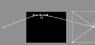
To create a curve in your straight motion path, click the motion path and drag in the direction you want the path to curve.
As you drag the motion path into a curve, additional keyframes appear on the motion path automatically; the keyframes have little handles, called Bézier handles, which you use to sculpt the motion path’s curves (Figure 15.49).
Click the Canvas Play button to play back the first draft of your edited motion path.
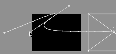
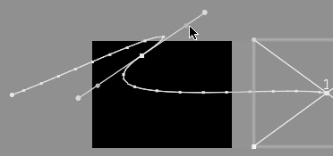
To adjust the curve, click a keyframe’s Bézier handle; then do any of the following:
Drag the handle away from the keyframe to deepen the curve.
Drag the handle toward the keyframe to reduce the curve.
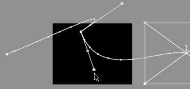
Rotate the handle to change the direction of the curve relative to that keyframe (Figure 15.50).
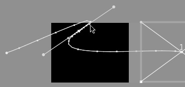
Command-drag to restrict rotation to one side of the curve (Figure 15.51). Release the Command key to set the new relationship between the two curves.
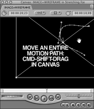
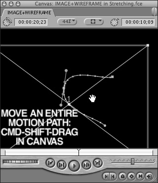
To reposition an entire motion path:
Choose the Selection tool from the Tool palette.
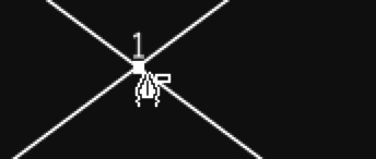
In the Canvas, hold down the Command and Shift keys; then place the pointer near the motion path that you want to reposition.
The Selection tool turns into a Hand pointer when you position it correctly (Figure 15.52).
Drag the motion path to a new position.
The entire motion path repositions but does not change its shape or timing (Figure 15.53).
Once you have created it, you can adjust a motion path directly in the Canvas (or Viewer) by moving or deleting motion path keyframes. When you’re working with a motion path in the Canvas, the playhead doesn’t need to be over a keyframe for you to move or delete it, nor does the playhead location prohibit you from adding a motion path keyframe.
Remember that a keyframe is like an edit point: It signals a change in an effect. In a motion path, keyframes are placed automatically only when a motion path changes direction. A straight motion path requires only two keyframes: a start keyframe and an end keyframe.
The two motion path variables you are adjusting are your clip’s speed of travel (determined by the ratio of duration to distance between keyframes) and the path’s route (indicated by the shape of the white line that connects the start and end keyframes). The little dots that appear between the keyframes indicate the duration between path points.
Final Cut Express features two types of motion path keyframes: corners and curves. The default motion path keyframe is a corner, which creates an instant change in direction. If you want a smoother motion effect, the curve keyframes have Bézier handles, which you can use to fine-tune the shape of the path’s curve, as well as ease handles, which you can use to fine-tune your clip’s speed immediately before and after the keyframe location.
You switch a corner type motion path keyframe to a curve type as the first step in smoothing your motion path and finessing its timing.
Tip
You can use the Shift and Command keys while dragging a Bézier or ease handle to influence the connections between the angles of the curve.
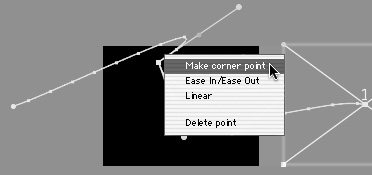
To toggle a keyframe between corner and curve types in Wireframe mode:
With your clip displayed in Wireframe mode in the Canvas, Control-click a keyframe and choose one of the following options:
Make Corner Point toggles the keyframe from a curve type to a corner type (Figure 15.54).
Ease In/Ease Out accesses the ease handles, which are discussed later in this section.
Linear applies a constant rate of speed to the path immediately before and after the keyframe location.
Delete Point deletes the keyframe.
You can increase the speed of a clip’s movement by shortening the timecode duration between two keyframes without changing their spatial coordinates. The clip’s speed increases, since it takes less time to travel between the two locations on your motion path. Or keep the time interval the same and move the keyframes farther apart on the motion path, so the clip travels farther in the same amount of time. Other timing factors in your sequence composition will dictate your choice.
Ease handles, located in the Canvas between the Bézier handles and the keyframe’s position point (Figure 15.55), fine-tune the rate of speed at which a clip approaches and leaves a curve keyframe. The default Ease In and Out setting slows the speed on the motion path by 33 percent before and after the keyframe, but you can customize that setting. Drag both handles to set the clip’s ease in and ease out to the same rate, or drag the handles separately to set different ease-in and ease-out rates.
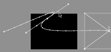
Figure 15.55. Ease handles are located about midway between the Bézier handles and the keyframe’s position point.
To make a clip ease in and out of a keyframe:
With the Canvas in Image+Wireframe mode, start with a curve motion path keyframe.
Choose the Selection tool.
Click the curve keyframe; then do one of the following:
Drag the ease handle away from the keyframe to increase the clip’s speed as it passes through the keyframe’s location on the motion path (Figure 15.56).
Drag the handle toward the keyframe to slow the clip’s speed as it passes through the keyframe’s location on the motion path (Figure 15.57).
Drag either ease handle to adjust the path’s timing on both sides of the keyframe equally.
Shift-drag one ease handle to adjust the path’s timing only on the selected side.
Play back in Image+Wireframe mode to see your results.
Tip
You can copy and paste motion paths between clips or sequences by using the Paste Attributes command on the Edit menu. Check the Scale Attributes box when you paste attributes onto your destination clip, and you can reuse a motion path on a different clip that’s shorter or longer than the original.