This chapter discusses how to design quality of service into a network, and includes the following sections:
This chapter introduces quality of service (QoS) models, tools, and design guidelines.
We first introduce what QoS is and why it is an important service in today’s networks. The QoS-related requirements for various types of traffic are described next. Two models for deploying end-to-end QoS in a network are then examined: Integrated Services (IntServ) and Differentiated Services (DiffServ). QoS tools, including classification and marking, policing and shaping, congestion avoidance, congestion management, and link-specific tools are explained. The Cisco Automatic QoS (AutoQoS) feature on routers and switches is introduced; this tool provides a simple, automatic way to enable QoS configurations in conformance with Cisco’s best-practice recommendations. We conclude with some QoS design considerations.
Note
Appendix B, “Network Fundamentals,” includes material that we assume you understand before reading the rest of the book. Thus, we encourage you to review any of the material in Appendix B that you are not familiar with before reading the rest of this chapter.
QoS can be defined as the “measure of transmission quality and service availability of a network (or internetworks).”[1] Another definition of QoS is that it “refers to the ability of a network to provide improved service to selected network traffic over various underlying technologies.”[2] The common theme here is that QoS ensures quality service to network traffic.
Recall from Chapter 1, “Network Design,” that QoS is an intelligent network service—a supporting, but necessary, service provided by the network. QoS is not an ultimate goal of a network; rather, it is a necessary service that enables network applications. In contrast, voice communication is an example of an intelligent network solution—a network-based application that requires the support of network services, including QoS.
A network within which no QoS strategy, tools, or techniques have been implemented treats all traffic the same way and is said to be offering a best-effort service—it does its best to send all packets and treats all packets equally. So, if a company’s CEO is on a voice call with an important client and someone starts to download a movie to watch over the weekend, the network treats both types of traffic equally and does not consider voice traffic any differently if contention for network resources exists. This is probably not the way the CEO imagined the network should work. The QoS strategies presented in this chapter can be used to ensure, for example, that voice traffic takes priority over movie downloads.
A converged network is one in which data, voice, and video traffic coexist on a single network. These diverse traffic types have different characteristics and hence different quality requirements. The QoS tools introduced in this chapter are designed to improve the QoS in networks with a variety of traffic types. Specifically, the QoS parameters affected are the factors that affect the quality of the service provided to the transmission of traffic: packet loss, delay, and jitter.
Packets are typically lost because of network congestion. The effect of the loss depends on the application being used. For example, loss of a single voice packet is not detrimental to the quality of the voice signal at the receiving end because it can be interpolated from other voice samples; loss of multiple voice packets, though, can cause the received message to be unintelligible. On the other hand, a packet sent through the Transmission Control Protocol (TCP) (for example, a file sent with a File Transfer Protocol [FTP] application) that is lost would amplify the congestion problem because it would have to be resent and would therefore consume more bandwidth.
Delay, also called latency, is the time it takes packets to travel through the network. Delay has two components: fixed and variable. These terms are described as follows:
Fixed delays are the predictable delays associated with preparing and encapsulating the data, transmitting it onto the wire, and having it travel to the receiver. Fixed delays can be further categorized as follows:
Processing or packetization delay—. The time it takes to create the data that is to be sent. For example, for voice traffic, the analog voice must be sampled, converted to digital data, and then encapsulated in packets.
Serialization delay—. The time it takes to transmit the data onto the wire. This delay is related to the speed of the physical link.
Propagation delay—. The time it takes the data to travel on the network. In most cases, propagation delay is small enough that it can be ignored.
Variable delays are the unpredictable delays that result from a packet waiting for other traffic that is queued on the interface to be sent. As more and larger packets are being sent, these delays increase.
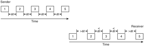
Jitter is the variation in the delay experienced by packets in the network. In the example of jitter illustrated in Figure 6-1, the sender sends the data out at consistent time intervals, Δt. The receiver is seeing a variation in the delay of received packets—some are greater than Δt while others are less than Δt. Jitter is usually not noticeable for applications such as file transfers. However, applications such as voice are sensitive to differences in packet delays—for example, a listener might hear silent pauses where none should exist.
Note
Special dejitter buffers are incorporated into voice-enabled routers to smooth out the differences in packet delays by converting the variable delay to a fixed delay. However, these dejitter buffers increase the overall delay in the network.
QoS allows you to control and predict the service provided by your network for a variety of applications. Implementing QoS has many advantages, including the following:[3]
Controlling which network resources (bandwidth, equipment, wide-area facilities, and so on) are being used
Ensuring that your resources are used efficiently by the mission-critical applications—those that are most important to your business—and that other applications get fair service without interfering with this mission-critical traffic
Creating a solid foundation for a fully integrated converged network in the future
Later in this chapter (in the “Classification and Marking” section), the Cisco QoS Baseline is presented, representing best-practice recommendations for how QoS should be implemented for various types of traffic. These recommendations are based on the requirements for that traffic, as described in this section.
Voice traffic (discussed in more detail in Chapter 7, “Voice Transport Design”) is sensitive to delays, variation in delays (jitter), and packet loss. The guidelines for ensuring acceptable voice quality are as follows:
The one-way delay should be no more than 150 milliseconds (ms).
The jitter should be no more than 30 ms.
No more than 1 percent of packets should be lost.
Note
While 150 ms is the standard for acceptable voice delay, tests have shown that a negligible quality difference is found with a 200-ms delay.
The bandwidth required for voice traffic varies with the algorithm that compresses the traffic and the specific Layer 2 frame type it is encapsulated in, as described further in Chapter 7. Call-signaling traffic requires at least 150 bps (not including Layer 2 overhead), depending on the protocols used.
Interactive video, or video conferencing, has the same delay, jitter, and packet loss requirements as voice traffic. The difference is the bandwidth requirements—voice packets are small while video conferencing packet sizes can vary, as can the data rate. A general guideline for overhead is to provide an additional 20 percent of bandwidth over that required by the data.
Streaming video has different requirements than interactive video. An example of the use of streaming video is when an employee views an online video during an e-learning session. As such, this video stream is not nearly as sensitive to delay or loss as interactive video is—requirements for streaming video include a loss of no more than 5 percent and a delay of no more than 4 to 5 seconds. Depending on the importance to the organization, this traffic can be given precedence over other traffic.
Note
When you start watching a video stream (a recording) on the Internet, you might see messages such as “Buffering x%” before the video starts in the application that you are running. This buffering is to compensate for any transmission delays that might occur.
Many other types of application data exist within an organization. For example, some are relatively noninteractive and therefore not delay sensitive (such as e-mail), while others involve users entering data and waiting for responses (such as database applications) and are therefore very delay sensitive. Data can also be classified by its importance to the overall corporate business objectives. For example, a company that provides interactive, live e-learning sessions to its customers would consider that traffic to be mission-critical, while a manufacturing company that is one of the e-learning company’s customers might consider that same traffic important, but not critical to its operations.
Traffic related to the operation of the network itself must also be considered. One example of this type of traffic is routing protocol messages—the size and frequency of these messages vary, depending on the specific protocol used and the stability of the network. Network management data is another example, including Simple Network Management Protocol (SNMP) traffic between network devices and the network management station.
Two models exist for deploying end-to-end QoS in a network for traffic that is not suitable for best-effort service: IntServ and DiffServ. End-to-end QoS means that the network provides the level of service required by traffic throughout the entire network, from one end to the other.
Key Point
With IntServ, an application requests services from the network, and the network devices confirm that they can meet the request, before any data is sent. The data from the application is considered to be a flow of packets.
In contrast, with DiffServ, each packet is marked as it enters the network based on the type of traffic that it contains. The network devices then use this marking to determine how to handle the packet as it travels through the network.
IntServ uses an explicit signaling mechanism from applications to network devices. The application requests a specific service level, including, for example, its bandwidth and delay requirements. After the network devices have confirmed that they can meet these requirements, the application is assumed to only send data that requires this level of service.
Applications in an IntServ environment use the Resource Reservation Protocol (RSVP) to indicate their requirements to the network devices. The network devices keep information about the flow of packets, and ensure that the flow gets the resources it needs by using appropriate queuing (prioritizing traffic) and policing (selectively dropping other packets) methods. Two types of services provided in an IntServ environment are as follows:
Guaranteed Rate Service—. This service allows applications to reserve bandwidth to meet their requirements. The network uses weighted fair queuing (WFQ) with RSVP to provide this service. (WFQ is described in the “Congestion Management” section, later in this chapter.)
Controlled Load Service—. This service allows applications to request low delay and high throughput, even during times of congestion. The network uses RSVP with weighted random early detection (WRED) to provide this kind of service. (WRED is described in the “Congestion Avoidance” section, later in this chapter.)
Because IntServ requires RSVP on all network devices, it is currently not used as much as DiffServ.
An application in a DiffServ environment does not explicitly signal the network before sending data. Instead, the network tries to deliver a specific level of service based on the QoS specified in the header of each packet. Network devices, typically on the edge of the network, are configured to classify and mark packets according to their source, the destination, or the type of traffic in them. Devices within the network then provide appropriate resources based on this marking. For example, packets that contain voice traffic are usually given higher priority than file transfer data because of the unique requirements of voice.
The Cisco Internet Operating System (IOS) incorporates QoS features that support DiffServ, as described in the following section.
Some of the various tools that implement QoS are described in this section and illustrated in Figure 6-2.
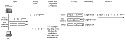
Many devices send data into a network. In the example shown in Figure 6-2, an IP phone produces packets that contain voice traffic, and a PC sends file transfer data. As the data enters the network, it is analyzed and classified according to how it should be dealt with in the network. After it is classified, the data is marked accordingly.
Key Point
Classification and marking form the basis for the rest of the QoS tools; it is here that business policies, priorities, and so forth are first implemented.
The markings can then be used by other tools. For example, packets can be dropped by policing tools so that the maximum rate on an interface is not exceeded. Or packets can be dropped by congestion-avoidance tools to avoid anticipated interface congestion. Remaining packets are then queued, again according to their markings, and scheduled for output on the interface. Other tools, such as compression, can be implemented on the interface to reduce the bandwidth consumed by the traffic.
The following sections explore these QoS tools:
Classification and Marking
Policing and Shaping
Congestion Avoidance
Congestion Management
Link-Specific Tools
AutoQoS
Before any traffic can be given priority over or treated differently than other traffic, it must first be identified.
Key Point
Classification is the process of analyzing packets and sorting them into different categories so that they can then be suitably marked; after they are marked, the packets can be treated appropriately.
Marking is the process of putting an indication of the classification of the packet within the packet itself so that it can be used by other tools.
The point within the network where markings are accepted is known as the trust boundary; any markings made by devices outside the trust boundary can be overwritten at the trust boundary. Establishing a trust boundary means that the classification and marking processes can be done once, at the boundary; the rest of the network then does not have to repeat the analysis. Ideally, the trust boundary is as close to end devices as possible—or even within the end devices. For example, a Cisco IP phone could be considered to be a trusted device because it marks voice traffic appropriately. However, a user’s PC would not usually be trusted because users could change markings (which they might be tempted to do in an attempt to increase the priority of their traffic).
Classification can be done based on data at any of the OSI layers. For example, traffic can be differentiated based on the Layer 1 physical interface that it came in on or the Layer 2 source Media Access Control (MAC) address in the Ethernet frame. For Transmission Control Protocol/Internet Protocol (TCP/IP) traffic, differentiators include the source and destination IP addresses (Layer 3), the transport (Layer 4) protocol—TCP or User Datagram Protocol (UDP), and the application port number (indicating Layer 7).
Some applications require more analysis to correctly identify and classify them. For these cases, the Cisco Network-Based Application Recognition (NBAR) classification software feature, running within the IOS on Cisco routers, can be used. NBAR allows classification (and therefore marking) of a variety of applications, including web-based and other difficult-to-classify protocols that use dynamic TCP/UDP port assignments. For example, Hypertext Transfer Protocol (HTTP) traffic can be classified and marked by specifying uniform resource locators (URLs) so that a customer who is accessing an online ordering page could be given priority over someone accessing a general information page. Support for new protocols can be easily and quickly added through downloadable packet description language modules (PDLMs).
Marking can be done either in the Layer 2 frame or in the Layer 3 packet.
For Ethernet frames, Layer 2 marking can be done using the following methods:[5]
For an Institute of Electrical and Electronics Engineers (IEEE) 802.1q frame, the three 802.1p user priority bits in the Tag field are used as class of service (CoS) bits. (Recall from Chapter 2 that 802.1q is a standard trunking protocol in which the trunking information is encoded within a Tag field that is inserted inside of the frame header itself.)
For an Inter-Switch Link (ISL) frame, three of the bits in the user field in the ISL header are used as CoS bits. (Recall from Chapter 2 that ISL is a Cisco-proprietary trunking protocol that encapsulates the data frame between a 26-byte header and a 4-byte trailer.)
No CoS representation exists for non-802.1q/non-ISL frames.
Because the CoS is represented by 3 bits, it can take on one of eight values, 0 through 7.
Key Point
Layer 2 markings are not useful as end-to-end QoS indicators because the media often changes throughout a network (for example, from Ethernet to a Frame Relay wide-area network [WAN]). Thus, Layer 3 markings are required to support end-to-end QoS.
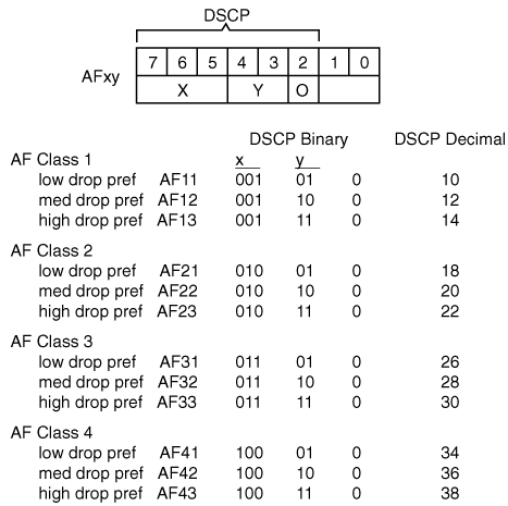
For IP version 4 (IPv4), Layer 3 marking can be done using the type of service (ToS) field in the packet header. Recall (from Appendix B) that this 8-bit field is the second byte in the IP packet header. (Figure B-11 illustrates all the fields in the IP packet header.) Originally, only the first 3 bits were used; these bits, called the IP Precedence bits, are illustrated in the middle of Figure 6-3. Packets with higher precedence values should get higher priority within the network. Because 3 bits again can only specify eight marking values, IP precedence does not allow a granular classification of traffic.
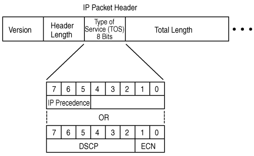
Thus, more bits are now used: The first 6 bits in the ToS field are now known as the DiffServ Code Point (DSCP) bits, and are illustrated in the lower portion of Figure 6-3. (The lower 2 bits in the ToS field are used for explicit congestion notification [ECN], which is described in the “Congestion Avoidance” section, later in this chapter.) With 6 bits, DSCP allows 64 marking values.
DSCP values can be expressed numerically (with binary values from 000000 through 111111 or decimal values from 0 through 63) or by using Per-Hop Behavior (PHB) values; PHBs are just keywords that represent some numeric DSCP values. (The name per-hop behavior indicates that each device, or hop, should behave consistently when determining how to treat a packet.)
Four PHB classes exist; they are described as follows:
Default or Best Effort (BE) PHB—. This PHB has a DSCP binary value of 000000 and represents the best-effort service.
Class Selector (CS) PHB—. This PHB has the lower three DSCP bits set to 000. Because this PHB uses only the upper 3 bits, it is compatible with the IP precedence values and is in fact written as CSx, where x is the decimal IP precedence value. For example, the CS PHB with the value 011000 represents IP precedence binary 011 or decimal 3; it is written as CS3.
Expedited Forwarding (EF) PHB—. This PHB represents a DSCP value of binary 101110 (decimal 46) and provides a low-loss, low-latency, low-jitter, and guaranteed bandwidth service. The EF PHB should be reserved for only the most critical applications, such as voice traffic, so that if the network becomes congested, the critical traffic can get the service it requires.
Assured Forwarding (AF) PHBs—. Four classes of AF PHBs exist, each with three drop preferences. These classes are represented as AFxy, where x is the class (a value from 1 to 4) and y is the drop preference (a value from 1 to 3). The AF class is determined by the upper 3 bits of the DSCP, while the drop preference is determined by the next 2 bits. (The lowest bit is always set to 0.) A drop preference of 1 is the lowest and 3 is the highest; this field determines which traffic should be dropped in times of congestion. For example, AF21 traffic would be dropped less often than AF22 traffic. Figure 6-4 illustrates the AF PHBs.
Key Point
We found that it is easy to get lost in the details of QoS markings, especially when the different PHBs, AF classes, and so forth are introduced.
To hopefully avoid this confusion, remember these key points about QoS DSCP markings:
The ToS field within an IPv4 packet header marks, or indicates, the kind of traffic that is in the packet. This marking can then be used by other tools within the network to provide the packet the service that it needs.
The first 6 bits in the ToS field are known as the DSCP bits.
DSCP values can be represented numerically (in binary or decimal) or with keywords, known as PHBs. Each PHB (BE, CSx, EF, and AFxy) represents a specific numeric DSCP value and therefore a specific way that traffic should be handled.
Cisco has created a QoS Baseline that provides recommendations to ensure that both its products, and the designs and deployments that use them, are consistent in terms of QoS. Although the QoS Baseline document itself is internal to Cisco, it includes an 11-class classification scheme that can be used for enterprises; this QoS Baseline suggestion for enterprise traffic classes is provided in Figure 6-5. This figure identifies the 11 types of traffic and the QoS marking that each type should be assigned. As described earlier, the QoS marking is either a Layer 2 CoS (specified within the 802.1q Tag field or ISL header) or a Layer 3 value marked in the IP packet header. The Layer 3 markings can either be done with a 3-bit IP precedence value (shown in the IPP column in Figure 6-5) or with a 6-bit DSCP value; both the numeric DSCP value and the PHB keyword representation of that value are shown in the figure.
![Cisco QoS Baseline Provides Guidelines for Classification and Marking[6]](http://imgdetail.ebookreading.net/design/12/1587052229/1587052229__campus-network-design__1587052229__graphics__06fig05.gif)
The classes of traffic in the QoS Baseline are defined as followed:
IP Routing class—. This class is for IP routing protocol traffic such as Border Gateway Protocol (BGP), Enhanced Interior Gateway Routing Protocol (EIGRP), Open Shortest Path First (OSPF), and so forth.
Voice class—. This class is for Voice over IP (VoIP) bearer traffic (the conversation traffic), not for the associated signaling traffic, which would go in the Call Signaling class.
Interactive Video class—. This class is for IP videoconferencing traffic.
Streaming Video class—. This class is either unicast or multicast unidirectional video.
Mission-Critical Data class—. This class is intended for a subset of the Transactional Data applications that are most significant to the business. The applications in this class are different for every organization.
Call Signaling class—. This class is intended for voice and video-signaling traffic.
Transactional Data class—. This class is intended for user-interactive applications such as database access, transactions, and interactive messaging.
Network Management class—. This class is intended for traffic from network management protocols, such as SNMP.
Bulk Data class—. This class is intended for background, noninteractive traffic, such as large file transfers, content distribution, database synchronization, backup operations, and e-mail.
Scavenger class—. This class is based on an Internet 2 draft that defines a “less-than-Best Effort” service. If a link becomes congested, this class will be dropped the most aggressively. Any nonbusiness-related traffic (for example, downloading music in most organizations) could be put into this class.
Best Effort class—. This class is the default class. Unless an application has been assigned to another class, it remains in this default class. Most enterprises have hundreds, if not thousands, of applications on their networks; the majority of these applications remain in the Best Effort class.
Key Point
The QoS Baseline does not mandate that these 11 classes be used; rather this classification scheme is an example of well-designed traffic classes. Enterprises can have fewer classes, depending on their specific requirements, and can evolve to using more classes as they grow. For example, at one point, Cisco was using a 5-class model (the minimum recommended in a network with voice, video, and data) on its internal network.[7]
Figure 6-6 illustrates an example strategy for expanding the number of classes over time—from a 5-class, to an 8-class, and eventually to the 11-class model—as needs arise.
![The Number of Classes of Service Can Evolve as Requirements Change[8]](http://imgdetail.ebookreading.net/design/12/1587052229/1587052229__campus-network-design__1587052229__graphics__06fig06.gif)
After traffic has been classified and marked and sent on its way through the network, other devices can then read the markings and act accordingly. The following sections examine the QoS tools that these devices can use.
Policing and shaping tools identify traffic that violates some threshold or service-level agreement (SLA). The two tools differ in the way that they respond to this violation.
Key Point
Policing tools drop the excess traffic or modify its marking.
Shaping tools buffer the extra data until it can be sent, thus delaying but not dropping it.
The difference between these tools is illustrated in Figure 6-7.
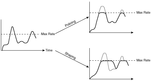
The diagram on the left in Figure 6-7 illustrates traffic that is being presented to an interface; note that some of the traffic exceeds the maximum rate allowed on the interface. If policing tools were configured on the interface, the excess traffic would simply be dropped, as indicated in the upper-right diagram. In contrast, the lower-right diagram shows that shaping tools would send all the data by delaying some of it until bandwidth is available.
The Cisco IOS traffic policing feature allows control of the maximum rate of traffic sent or received on an interface. It is often configured on interfaces at the edge of a network to limit traffic into or out of the network. Traffic that does not exceed the specified rate parameters is sent, while traffic that exceeds the parameters is either dropped or is sent with a lower priority.
Note
Committed access rate (CAR) is an older IOS policing tool that can be configured to rate-limit (drop) certain traffic if it exceeds a specified speed. It can also be configured to set or change the markings within the packet header for traffic, depending on whether it meets or exceeds the acceptable rate.
Traffic shaping allows you to control the traffic going out of an interface to match its flow to the speed of the destination interface or to ensure that the traffic conforms to particular policies. The IOS software supports the following QoS traffic-shaping features:
Generic Traffic Shaping (GTS)—. GTS provides a mechanism to reduce the flow of outbound traffic on an interface to a specific bit rate. You can use access lists to define particular traffic to be shaped. GTS is useful when the receiving device has a lower access rate into the network than the transmitting device.
Class-based shaping—. This type of shaping provides the means for configuring traffic shaping on a class of traffic, based on the marking in the packet header, rather than only on an access list basis. Class-based shaping also allows you to specify average rate or peak rate traffic shaping.
Distributed Traffic Shaping (DTS)—. DTS is similar to class-based shaping; however, DTS is used on devices that have distributed processing (such as the Cisco 7500 Versatile Interface Processor [VIP]) and don’t support class-based shaping.
Frame Relay Traffic Shaping (FRTS)—. Although GTS works for Frame Relay, FRTS offers the following capabilities that are more specific to Frame Relay networks:
Rate enforcement on a per–virtual circuit (VC) basis—. A peak rate can be configured to limit outbound traffic to either the committed information rate (CIR) or to some other defined value.
Generalized backward explicit congestion notification (BECN) support on a per-VC basis—. The router can monitor the BECN field in frames and throttle traffic if necessary.
Priority and custom queuing support on a per-VC basis—. This allows finer granularity in the queuing of traffic on individual VCs.
Note
Priority and custom queuing are described in the “Congestion Management” section, later in this chapter.
Key Point
Congestion-avoidance techniques monitor network traffic loads so that congestion can be anticipated and then avoided, before it becomes problematic.
If congestion-avoidance techniques are not used and interface queues get full, packets trying to enter the queue will be discarded, regardless of what traffic they hold. This is known as tail drop—the packets arriving after the tail of the queue are dropped.
In contrast, congestion-avoidance techniques allow packets from streams identified as being eligible for early discard (those with lower priority) to be dropped when the queue is getting full.
Congestion avoidance works well with TCP-based traffic; TCP has a built-in flow control mechanism so that when a source detects a dropped packet, the source slows its transmission.
Weighted random early detection (WRED) is the Cisco implementation of the random early detection (RED) mechanism. RED randomly drops packets when the queue gets to a specified level (in other words, when it is nearing full). RED is designed to work with TCP traffic: When TCP packets are dropped, TCP’s flow-control mechanism slows the transmission rate and then progressively begins to increase it again. RED therefore results in sources slowing down and hopefully avoiding congestion.
WRED extends RED by using the IP precedence in the IP packet header to determine which traffic should be dropped; the drop-selection process is weighted by the IP precedence. Similarly, DSCP-based WRED uses the DSCP value in the IP packet header in the drop-selection process. WRED selectively discards lower-priority (and higher-drop preference for DSCP) traffic when the interface begins to get congested.
Starting in IOS Release 12.2(8)T, Cisco has implemented an extension to WRED called explicit congestion notification (ECN), which is defined in RFC 3168, The Addition of Explicit Congestion Notification (ECN) to IP, and uses the lower 2 bits in the ToS byte (as shown earlier in Figure 6-3). Devices use these two ECN bits to communicate that they are experiencing congestion. When ECN is in use, it marks packets as experiencing congestion (rather than dropping them) if the senders are ECN-capable and the queue has not yet reached its maximum threshold. If the queue does reach the maximum, packets are dropped as they would be without ECN.
While congestion avoidance manages the tail, or back, of queues, congestion management takes care of the front of queues.
Key Point
As the name implies, congestion management controls congestion after it has occurred. Thus, if no congestion exists, these tools are not triggered, and packets are sent out as soon as they arrive on the interface.
Congestion management can be thought of as two separate processes: queuing, which separates traffic into various queues or buffers, and scheduling, which decides from which queue traffic is to be sent next.
Queuing algorithms sort the traffic destined for an interface. Cisco IOS Software includes many queuing mechanisms. Priority queuing (PQ), custom queuing (CQ), and weighted fair queuing (WFQ) are the three oldest. IP Real-Time Transport Protocol (RTP) priority queuing was developed to provide priority for voice traffic, but it has been replaced by class-based weighted fair queuing (CBWFQ) and low latency queuing (LLQ). These queuing mechanisms are described as follows:
PQ—. A series of filters based on packet characteristics (for example, source IP address and destination port) are configured to place traffic in one of four queues—high, medium, normal, and low priority. For example, voice traffic could be put in the high queue and other traffic in the lower three queues. The high-priority queue is serviced first until it is empty. The lower-priority queues are only serviced when no higher-priority traffic exists; these lower-priority queues run the risk of never being serviced.
CQ—. Traffic is placed into one of up to 16 queues, and bandwidth can be allocated proportionally for each queue by specifying the maximum number of bytes to be taken from each queue. CQ services queues by cycling through them in a round-robin fashion, sending the specified amount of traffic (if any exists) for each queue before moving on to the next queue. If one queue is empty, the router sends packets from the next queue that has packets ready to send.
WFQ—. WFQ classifies traffic into conversations and applies weights, or priorities, to determine the relative amount of bandwidth each conversation is allowed. WFQ recognizes IP precedence values marked in IP packet headers. For example, WFQ schedules voice traffic first and then fairly shares the remaining bandwidth among high-volume flows.
IP RTP priority queuing—. This type of queuing provides a strict priority-queuing scheme for delay-sensitive traffic. This traffic can be identified by its RTP port numbers and classified into a priority queue. As a result, delay-sensitive traffic such as voice can be given strict priority over other nonvoice traffic.
Note
RTP is a protocol designed to be used for real-time traffic such as voice. RTP runs on top of UDP (to avoid the additional overhead and delay of TCP). RTP adds another header that includes some sequencing information and time-stamping information to ensure that the received data is processed in the correct order and that the variation in the delay is within acceptable limits.
CBWFQ—. CBWFQ provides WFQ based on defined classes but does not have a strict priority queue available for real-time traffic such as voice. All packets are serviced fairly based on weight; no class of packets can be granted strict priority.
LLQ—. LLQ is a combination of CBWFQ and PQ, adding strict priority queuing to CBWFQ. This allows delay-sensitive data, such as voice data, to be sent first, giving it preferential treatment over other traffic.
Key Point
Link-specific tools are those that are enabled on both ends of a point-to-point WAN connection to reduce the bandwidth required or delay experienced on that link. The QoS tools available include header compression (to reduce the bandwidth utilization) and link fragmentation and interleaving (LFI) (to reduce the delay encountered).
Voice packets typically have a small payload (the voice data) relative to the packet headers—the RTP, UTP, and IP headers add up to 40 bytes. So, compressing the header of such packets can have a dramatic effect on the bandwidth they require. RTP header compression, called cRTP, compresses this 40-byte header to 2 or 4 bytes.
Note
Voice compression, which reduces the size of the voice payload while still maintaining the quality at an acceptable level, is described in Chapter 7.
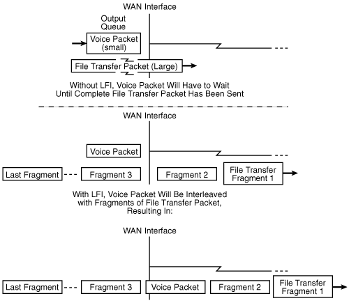
Even with queuing and compression in place, a delay-sensitive packet (such as a voice packet) could be ready to go out of a WAN interface just after a large packet (for example, part of a file transfer) has been sent on that interface. After forwarding of a packet out of an interface has begun, queuing has no effect and cannot recall the large packet. Therefore, a voice packet that gets stuck behind a large data packet on a WAN link can experience a relatively long delay and, as a result, the quality of the voice conversation can suffer. To counteract this, LFI can be configured on WAN links to fragment large packets (split them into smaller packets) and interleave those fragments with other packets waiting to go out on the interface. The smaller, delay-sensitive packets can travel with minimal delay. The fragments of the larger packets need to be reassembled at the receiving end, so the larger packets will experience some delay. However, because the applications sending these packets are not delay-sensitive, they should not be adversely affected by this delay. Figure 6-8 illustrates the LFI concept.
Note
Recall from Appendix B that the IPv4 packet header includes a 16-bit identification field consisting of 3 bits of flags and 13 bits of fragment offset. This field indicates whether the packet is a fragment and, if so, the offset of the fragment in the original packet. The receiving end can then reassemble the fragments to create the original packet.
The Cisco AutoQoS feature on routers and switches provides a simple, automatic way to enable QoS configurations in conformance with Cisco’s best-practice recommendations. Only one command is required. The router or switch then creates configuration commands to perform such things as classifying and marking VoIP traffic and then applying an LLQ queuing strategy on WAN links for that traffic. The configuration created by AutoQoS becomes part of the normal configuration file and can, therefore, be edited if required.
The first phase of AutoQoS, available in various versions of router IOS Release 12.3, only creates configurations related to VoIP traffic.
Note
The Cisco Feature Navigator tool, available at http://www.cisco.com/go/fn, allows you to quickly find the Cisco IOS and switch Catalyst Operating System (CatOS) Software release required for the features that you want to run on your network. For example, you can use this tool to determine the IOS release required to run AutoQoS on the routers in your network.
The second phase of AutoQoS is called AutoQoS Enterprise and includes support for all types of data. It configures the router with commands to classify, mark, and handle packets in up to 10 of the 11 QoS Baseline traffic classes. The Mission-Critical traffic class is the only one not defined, because it is specific to each organization. As with the earlier release, the commands created by AutoQoS Enterprise can be edited if required.
Note
Further information on AutoQoS can be found at http://www.cisco.com/en/US/products/ps6656/products_ios_protocol_opt and at http://www.cisco.com/en/US/tech/tk543/tk759/tk879/tsd_technology_support_protocol_home.html.
As discussed in Chapter 1, the first step in any design process is to determine the requirements that you are trying to meet. Only then should you attempt to design the network features to meet those requirements. Recall that this process is called a top-down approach. Compare this to a bottom-up approach, in which features (queuing, for example) are deployed on some interfaces without considering why they are being deployed.
Thus, when designing QoS features into your network, the QoS-related requirements of the network must be clearly defined. For example, if the network includes VoIP, video, or other delay-sensitive traffic, you need to determine whether that traffic is considered important enough to warrant providing it strict priority.
The number of classes of traffic that are to be used in the network and which applications are to be considered mission-critical need to be determined. In general, the number of applications in the Mission-Critical class should be minimized. If too many are considered critical, each one becomes just part of a large group and does not necessarily get the services it truly needs.
QoS can be considered “a system of managed unfairness”[9] in that some traffic is given less priority than other traffic, which might be seen by some users to be unfair. Thus, it is important to get agreements and buy-ins from high-level management about which data is considered critical to and within the organization, and to flow the QoS requirements from these agreements. Any complaints of unfairness can then be rebuked by referring to the agreements.
QoS tools can be used in all areas of the Enterprise Composite Network Model. As discussed earlier, the ideal trust boundary—where classification and marking of traffic are performed and trusted by the rest of the network—is as close to the end devices as possible. While the network administrator might not want to trust end users or their applications to set markings consistent with the network’s policy, the access switches to which the users’ PCs are connected could perform this task.
Using Layer 3 DSCP QoS markings allows QoS to be provided end to end throughout the network. If some access switches support only Layer 2 (CoS) markings, these markings must be mapped to the appropriate DSCP values; this would be a function performed by the distribution switches. These switches must also apply DSCP values to any traffic that has not been marked elsewhere. The campus core should not be involved in classifying and marking traffic; its role is to process the traffic quickly, based on previous markings.
Policing (dropping) traffic is best performed as close to the source of the traffic as possible, to avoid having the traffic travel through the network (and therefore consume resources such as bandwidth) unnecessarily. Again, within the campus infrastructure, policing should be performed on the access or distribution devices.
QoS tools can be enabled on either switches or routers. When performed in software however, QoS operations can consume considerable CPU resources, so ideally they should be enabled on devices that execute the necessary computations in hardware to achieve higher performance.
Although we typically think of applying queuing only to slow WAN links, LAN links can also be congested. For example, uplinks between switches that aggregate traffic from many other links are potential locations of congestion. Although this is less likely to occur than on WAN links, queuing should be deployed on any link that could potentially experience congestion, to provide the needed services to the network traffic. Queuing policies—in other words, how each traffic class is handled—should be consistent across the enterprise.
In this chapter, you learned about QoS models, tools, and design guidelines, including the following topics:
Why QoS is important in a converged network—one in which data, voice, and video traffic flows
The QoS-related requirements of various types of traffic
The two models for deploying end-to-end QoS: IntServ and DiffServ
The QoS tools available to implement QoS policies, including the following:
Classification and marking—. Analyzing packets and sorting them into different categories, and then putting an indication of the classification of the packet within the packet header itself
Policing—. Tools that drop the excess traffic or modify its marking
Shaping—. Tools that buffer extra data until it can be sent, thus delaying but not dropping it
Congestion avoidance—. Monitoring traffic loads so that congestion can be anticipated and then avoided, before it becomes problematic
Congestion management—. Controlling congestion after it has occurred
Link-specific tools—. Compression (to reduce the bandwidth utilization) and LFI (to reduce the delay experienced)
AutoQoS—. A simple, automatic way to enable QoS configurations in conformance with the Cisco best-practice recommendations
The Cisco QoS Baseline guidelines for classifying traffic
QoS design guidelines
| 1. | “Enterprise QoS Solution Reference Network Design Guide, Version 3.1,” June 2005, http://www.cisco.com/univercd/cc/td/doc/solution/esm/qossrnd.pdf. |
| 2. | “Cisco IOS Quality of Service Solutions Configuration Guide, Release 12.2.” http://www.cisco.com/en/US/products/sw/iosswrel/ps1835/products_configuration_guide_book09186a00800c5e31.html. |
| 3. | Ibid. |
| 4. | “Network-Based Application Recognition and Distributed Network-Based Application Recognition.” http://www.cisco.com/en/US/products/ps6350/products_configuration_guide_chapter09186a0080455985.html. |
| 5. | “QoS Classification and Marking on Catalyst 6500/6000 Series Switches Running CatOS Software.” http://www.cisco.com/en/US/products/hw/switches/ps700/products_tech_note09186a008014f8a8.shtml. |
| 6. | Adapted from “QoS Best Practices” session at Cisco Technical Symposium 2004, Tom Szigeti, October 5, 2004, Toronto, and Szigeti and Hattingh, End-to-End QoS Network Design: Quality of Service in LANs, WANs, and VPNs, Indianapolis, Cisco Press, 2004. |
| 7. | “QoS Best Practices” session at Cisco Technical Symposium 2004, Tom Szigeti, October 5, 2004, Toronto. |
| 8. | Ibid. |
| 9. | Szigeti and Hattingh, End-to-End QoS Network Design: Quality of Service in LANs, WANs, and VPNs, Indianapolis, Cisco Press, 2004. |