
2D Wireframe Geometry
|

Two dimensional wireframe geometries are points, lines, and planar curves. 2D wireframe geometry is stored in a sketch, which is represented by the Sketch class (Section 8.202). From a sketch, solids and surfaces can be created.
The creation of a sketch can be divided into three steps:
1. Creating sketch references and sketch objects
2. Creating sketch geometry
3. Creating constraints between the geometric elements in a sketch

A sketch reference is a plane or planar surface on which the 2D wire geometry of a sketch lies. By using a sketch reference, a sketch is positioned in space. Commonly used sketch references are origin planes (Section 3.2) or user-created planes (Section 6.4).
A sketch is always assigned to a body or geometrical set. This must be declared or created (Section 3.3) before a sketch can be created. If a body or geometrical set already exists, the Sketches property of the Body class (Section 8.9) or the HybridSketches property of the HybridBody class (Section 8.50) can be used to derive a list of all the sketches in a body.
The Sketches class (Section 8.204) enables the Add method to add another sketch to the sketch list. A sketch always needs a sketch reference. A plane or planar surface is used for a sketch reference. The result of this method is a sketch whose origin corresponds to the sketch references. All position values are based on the sketch’s origin.
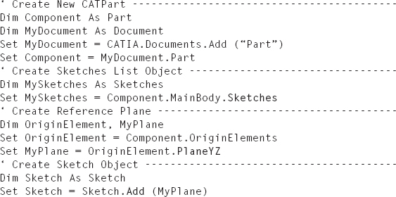
Example 5.1: Creating a Sketch
A sketch is created in the PartBody in a new CATPart. The reference of the sketch is the YZ plane. The result is shown in Figure 5.1.
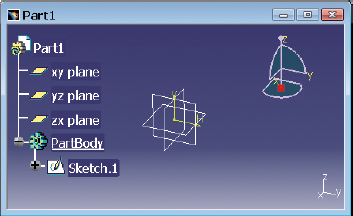
FIGURE 5.1 Result of the example “Creating a Sketch”

A sketch has a two-dimensional axis system with an H- and a V-axis that lie at the origin of the sketch. The orientation of the axes is based on the reference sketches. The axis system can be derived with AbsoluteAxis property of the Sketch class (Section 8.202).
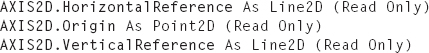
The Axis2D class (Section 8.7) has the HorizontalReference, Origin, and Vertical-Reference properties to read out the origin and the axes of a coordinate system. The origin elements of a sketch are often used to define constraints.
The axes of a sketch “Sketch” are read, and the objects “HAxis” and “VAxis” are assigned.
The Sketch class offers more than the possibility of the SetAbsoluteAxisData method to change the axis system of a sketch.
“Axis3D” is a field that is composed of nine values :
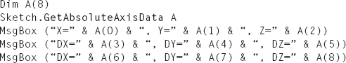
If the origin and the orientation of a sketch are to be read, the GetAbsoluteAxisData method is used.
Example 5.3: Reading the Data of a 2D-Axis System
The origin and orientation of the axes of a sketch “Sketch” are read and displayed in a output window.
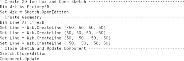
The points, lines, and curves of a sketch are created with the help of a 2D toolbox. A 2D toolbox is an object of the Factory2D class (Section 8.35) that provides the methods for defining geometry. A 2D toolbox is declared with the OpenEdition method of the Sketch class (Section 8.202). The method also opens a sketch for editing.
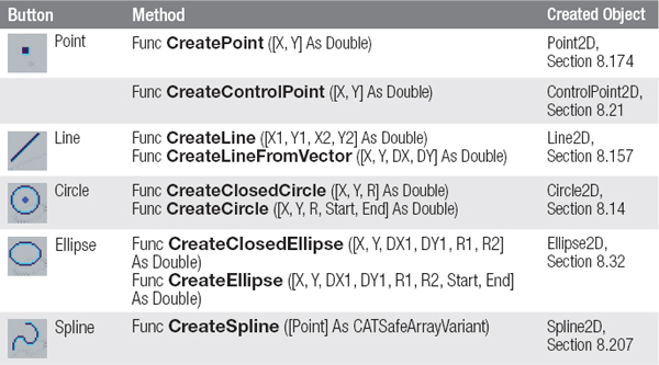
2D geometric elements can be created with a toolbox. An overview of the key elements and their methods is given in Table 5.1. The “X” and “Y” parameters always refer to the origin of a sketch.
TABLE 5.1 Overview of the Methods of the “Factory2D” Class (For details of the methods Factory2D, see Section 8.35.)
Once the geometric elements of a sketch are created, the sketch is closed with the CloseEdition method of the Sketch class, and the CATPart is recalculated with the Update method of the Part class (Section 8.168).
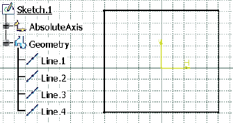
Example 5.4: Creating a Square
A sketch has been declared as an object “Sketch” and as a part “Component.” In the sketch, a square with an edge length of 100 mm is drawn symmetrically about the origin of the sketch (Figure 5.2).
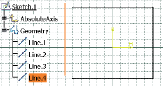
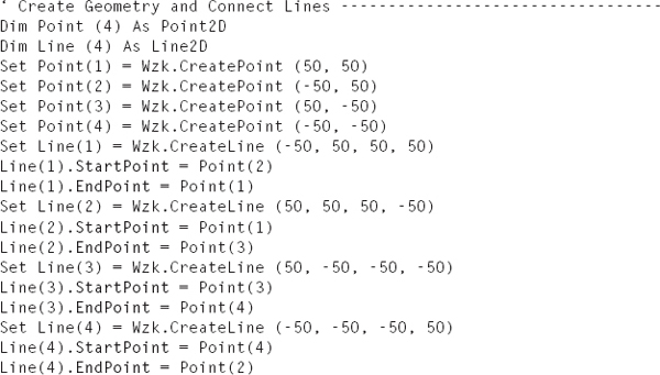
The result is a square whose lines have no relation to each other. In Sketcher, the lines can be moved using the arrow pointer (Figure 5.3). A relation between two lines can be prepared by the start and end points of both lines, and the created lines can be assigned. A start and end points can be assigned to a line with the Start-Point and EndPoint properties of the Curve2D class (Section 8.22). Curve2D is a parent class of the Line2D class.
The expanded macro reads:
If you now move a point or a line with the arrow pointer, the lines move together (Figure 5.4).

FIGURE 5.4 Square with associated lines
A construction element is a 2D geometric element that is not used for creating geometry but is used as a positioning aid for other 2D geometric elements. A construction element is represented by dashed lines in a sketch.
A rotation axis is the line that is defined as an axis of rotation for a revolved surface or revolved solid. A rotation axis is represented as dotted lines in a sketch.

The definition, whether the 2D geometry element is a standard or construction element, is performed with the Construction property of the Geometry2D class (Section 9.46). Since each 2D geometry element of the Geometry2D class has a parent class, it has this property. To declare an element as a construction element, the property is set to “True.”

The rotation axis of a sketch can be defined using the CenterLine property of the Sketch class (Section 8.202).
Example 5.5: Standard Element, Construction Element, and Rotation Axis
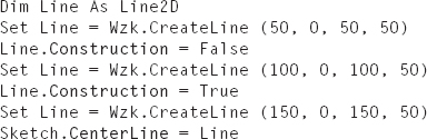
In a sketch “Sketch” that was opened with the toolbox “Wzk,” three lines are created. The first line is a standard element, the second is a construction element, and the third is a rotation axis in the sketch (Figure 5.5).
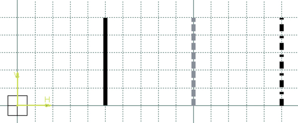
FIGURE 5.5 Result of the example “Standard Element, Construction Element, and Rotation Axis”
A constraint associates geometric elements of a sketch and allows a user to quickly modify the sketch. A constraint is represented by an object of the Constraint class (Section 8.19) and is stored in a list object of the Constraints class (Section 8.20). The list object is declared with the Constraints property of the Sketch class (Section 8.20.2) :
A constraint is created using the AddMonoEltCst, AddBiEltCst, and AddTriEltCst methods of the Constraints class. The methods differ by the number of references (Section 3.5) they process: “Mono” for one, “Bi” for two, and “Tri” for three references. A sketch in which a constraint is to be created must be opened with OpenEdition (Section 5.2).
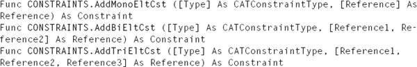
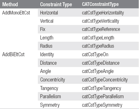
The parameter “Type” defines the type of constraint and is designated by a CATConstraintType identifier. An overview of the types of constraints is given in Table 5.2. A complete list can be taken from the Type property of the Constraint class.
TABLE 5.2 Important Constraint Types and Their Methods
In many cases, when a length, radius, distance, or angle is created, it should also be assigned a value. Access to the value of a measurement is allowed through Dimension property of the Constraint class (Section 8.19) :
The Dimension class (Section 8.24) offers a measurement with a value to be assigned because of the parent classes of the Value property.
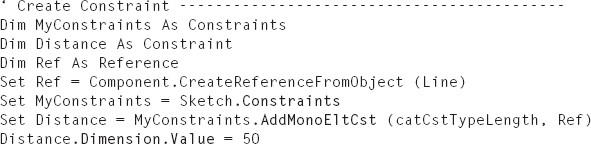
Example 5.6: Create Constraint
In a sketch, a line exists. The sketch and line are declared in a macro as the objects “Sketch” and “Line.” The line receives a length constraint with a value of 50 mm.
..................Content has been hidden....................
You can't read the all page of ebook, please click here login for view all page.