CHAPTER FIVE
PALLETS: PALLET STORAGE AND HANDLING SYSTEMS
5.3 Pallet Storage and Handling Systems Selection
We begin our RightHouse taxonomy (Figure 5.1) of pallet storage and handling systems by classifying the systems into (1) pallet storage systems and (2) pallet handling systems. Although the two subsystems work hand in hand, selection of the storage system is driven primarily by the desire to improve storage density and is dictated by the on-hand inventory and turnover of the items in pallet storage. The choice of the handling system is driven primarily by the desire for high handling productivity and tradeoffs in required capital investment.
Figure 5.1 RightHouse taxonomy of pallet storage and handling systems.

5.1 Pallet Storage Systems
Pallet storage systems fall into three subcategories based on the nature of the racking type: (1) pallet stacking systems, (2) static racking systems, and (3) dynamic racking systems. Each alternative is described in this section.
Pallet Stacking Systems
Pallet stacking systems have pallets stacked on top of each other, hence the name pallet stacking system. There are two types of pallet stacking systems—block stacking, often referred to as floor storage, and stacking frames.
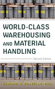
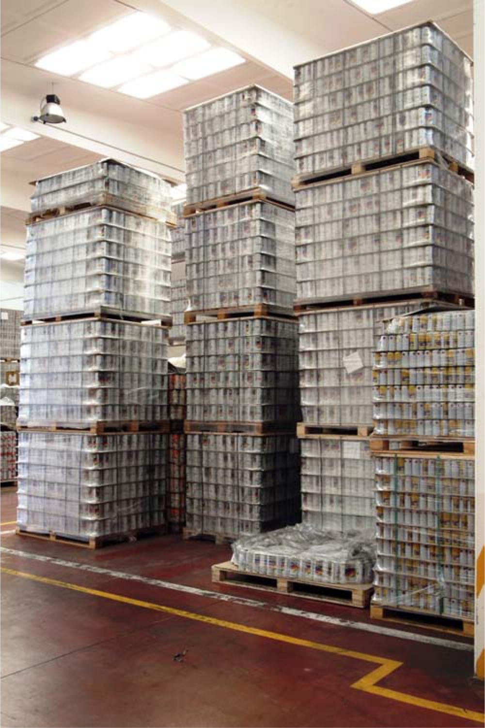
Block Stacking Block stacking (Figures 5.2 through 5.4) refers to unit loads stacked on top of each other and stored on the floor in storage lanes (blocks) typically 3 to 10 loads deep. Block stacking is particularly effective when there are multiple pallets on-hand per stock-keeping unit (SKU) and when several loads of the same SKU are received and/or withdrawn at one time. Because no racking is required, the investment in block stacking is low. Block stacking is easy to implement, and it allows near-infinite flexibility for floor-space configuration. Loads in a block are retrieved last in, first out (LIFO). Hence, if highly restrictive first in, first out (FIFO) requirements are in place, block stacking is not a feasible storage method (Figures 5.2 through 5.4).
Figure 5.2 Block stacking at a Coca-Cola plant warehouse North Carolina. Note that loads are stacked one high, two high, two and a half high (by straddling adjacent stacks), and three high depending on the weight of the product.

Figure 5.3 Floor storage may be the only reasonable pallet storage alternative in a warehouse with low clearings. Such was the case at this Japanese beverage wholesaler’s multi-story distribution center.
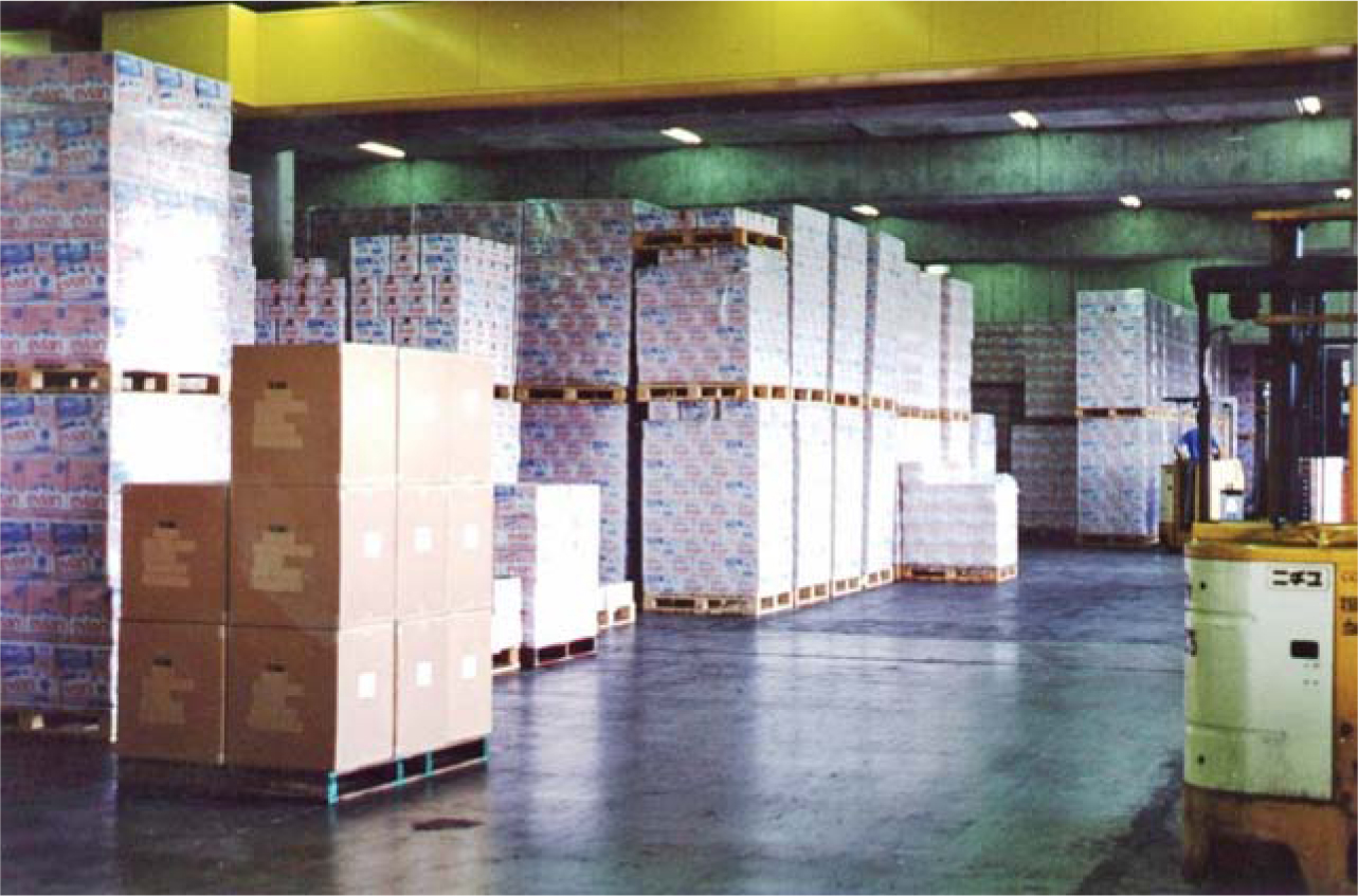
Figure 5.4 Block stacking with case picking front at a Coca-Cola warehouse.
Stack Height Constraints The storage density in block stacking systems is determined by two factors—the depth of the storage lane and the stacking height. Stacking height is constrained and determined by a mix of the following factors:
![]() Load surface shape. Irregularly shaped product does not stack efficiently.
Load surface shape. Irregularly shaped product does not stack efficiently.
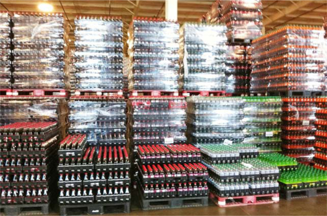
![]() Load weight. Heavy loads may crush one another (Figures 5.5 and 5.6).
Load weight. Heavy loads may crush one another (Figures 5.5 and 5.6).
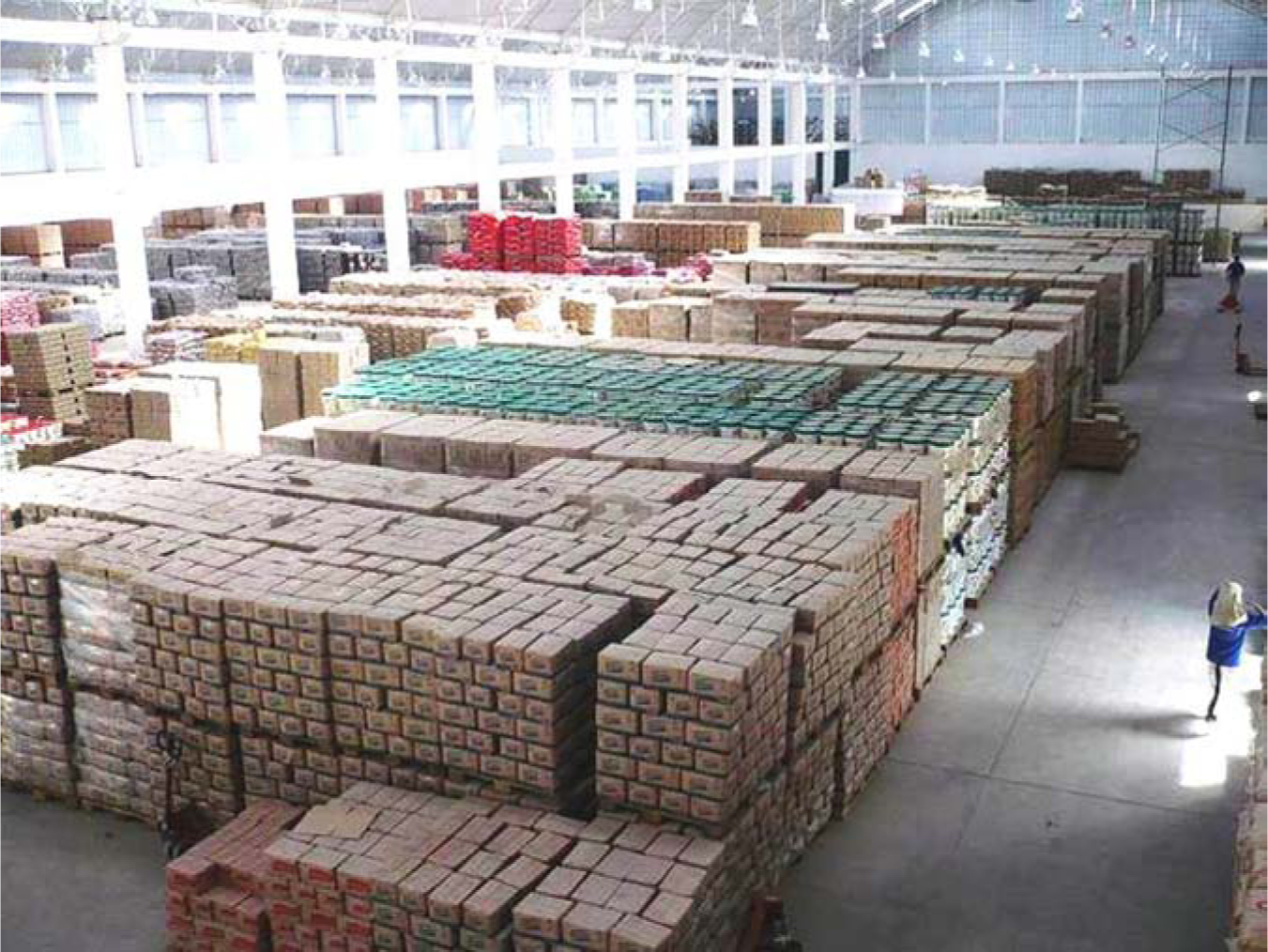
Figure 5.5 The height of block stacking in this cement manufacturer’s warehouse is constrained by product weight and shape.
Figure 5.6 Block stacking in an aluminum can plant. Lightweight and uniform loads permit four-high stacking.
![]() Packaging strength. Weak packaging will not support stacked loads.
Packaging strength. Weak packaging will not support stacked loads.
![]() Pallet condition. Poorly maintained pallets will not stack properly and may damage stacked product.
Pallet condition. Poorly maintained pallets will not stack properly and may damage stacked product.
![]() Floor loading restrictions. Some floors are not rated to support heavy loads (Figure 5.7).
Floor loading restrictions. Some floors are not rated to support heavy loads (Figure 5.7).
Figure 5.7 Block stacking in a raw materials warehouse (Lima, Peru).
![]() Weather. High humidity diminishes packaging strength.
Weather. High humidity diminishes packaging strength.
![]() Vehicle lift-height capacity. Obviously, loads may not be stacked higher than the lift-height capacity of the pallet-handling vehicle.
Vehicle lift-height capacity. Obviously, loads may not be stacked higher than the lift-height capacity of the pallet-handling vehicle.
![]() Building clear height. Even more obviously, loads may not be stacked higher than the ceiling clear height.
Building clear height. Even more obviously, loads may not be stacked higher than the ceiling clear height.
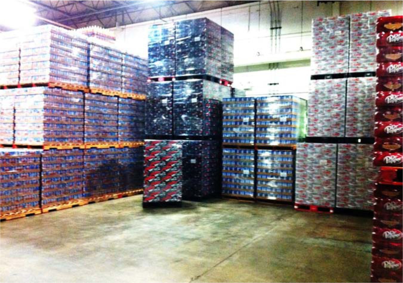
Honeycombing and Lane Depth Optimization Because only one SKU should be stored in a lane or stack, empty pallet spaces are created that cannot be used effectively until an entire lane is emptied. A ceiling view of a typical block stacking configuration with full, partially full, and empty lanes and stacks looks somewhat like a honeycomb—hence the term honeycombing references the loss of pallet storage capacity in block stacking (Figure 5.8). If lanes are too deep, the floor space in front of the back pallets is underutilized. If lanes are too short, too large a portion of the floor space is devoted to aisles. If the pallets are not easily stackable, too much of the available clear height is not useable.
Figure 5.8 Honeycombing at a large beverage distribution center.
Therefore, to maintain high utilization of the available storage positions, the lane depth must be carefully determined.
A lane-depth optimization analysis developed for a large consumer products company is shown in Figure 5.9. The lane depth yielding the lowest floor-space requirement for each item is recommended by the analysis.
Figure 5.9 RightLanes lane-depth optimization for a large consumer products company.
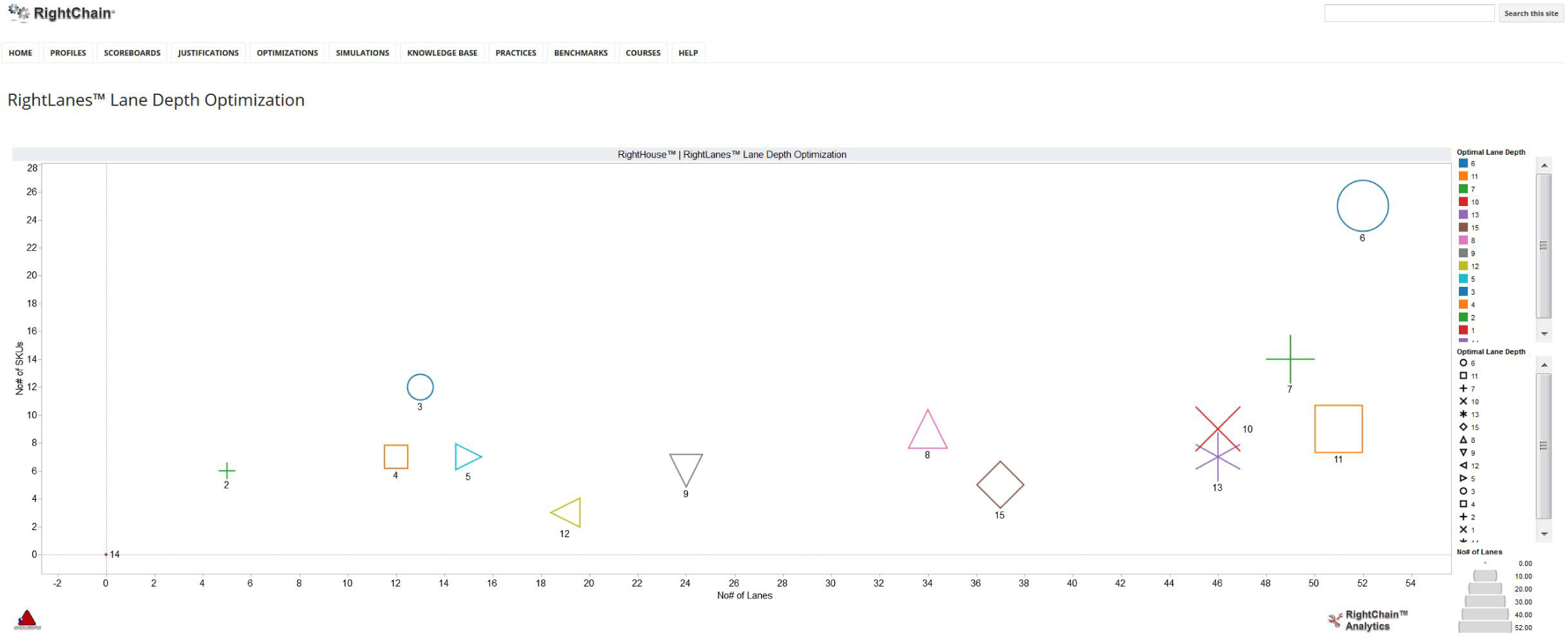
We use lane-depth optimization to minimize honeycombing. Our lane-depth optimization takes into account pallet dimensions, aisle dimensions, stack heights, and occupancy costs when computing an optimal storage lane depth for each SKU. An estimate of the optimal lane depth can be calculated with the following formula:
Optimal lane depth = [(aisle width × lot size)/(2 × load length × stack height)]1/2
In addition to optimizing lane depth, the following operating rules help to improve floor-space utilization in block stacking:
1. Retrieve from the most depleted lane first.
2. Rewarehouse when necessary.
3. Design lanes with access from both sides.
4. Mix lane depths within a bay.
Pallet Stacking Frames Pallet stacking frames (Figures 5.10 and 5.11) are either frames attached to standard wooden pallets or self-contained steel units made up of decks and posts. Stacking frames are portable and enable the user to stack material several loads high. When not in use, the frames can be disassembled and stored in a minimum amount of space.
Figure 5.10 Pallet stacking frames at NTT, (Tokyo, JAPAN).
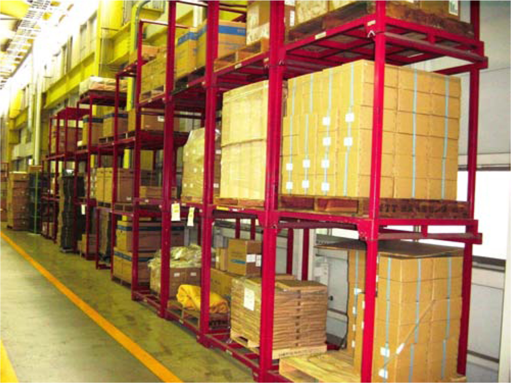
Figure 5.11 Inbound pallet stacking frames arriving to a Ford warehouse Georgia.
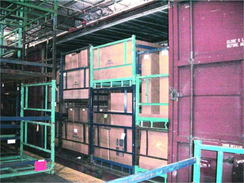
Stacking frames are commonly used when loads are not stackable and when other racking alternatives are not justifiable. In addition, because stacking frames can be leased, they are popular when there is a short-term spike in inventory. The storage-density losses due to honeycombing described earlier for block stacking also apply to stacking frames.
Static Racking Systems
Static racking systems include single-deep pallet racks, double-deep pallet racks, drive-in racks, and cantilever racks.
Single-Deep Pallet Racks Single-deep pallet racks (Figures 5.12 to 5.14), also called selective pallet racks, are a simple construction of metal uprights and cross-members providing immediate (pick-face) access to each load (i.e., no honeycombing). Because racking is supporting every load, stacking height is not limited by the stackability and/or crushability of the loads, and multiple SKUs can be stacked in the same vertical column of storage space.
Figure 5.12 Single-deep pallet racks at the American Cancer Society’s National Logistics Center Georgia. Note that the racks are four levels high; the top two levels are devoted to full-pallet reserve storage for the bottom two levels, which are devoted to case picking. Note also that as many cases as possible are positioned at the front of the case picking face to minimize lifting strain and improve productivity.
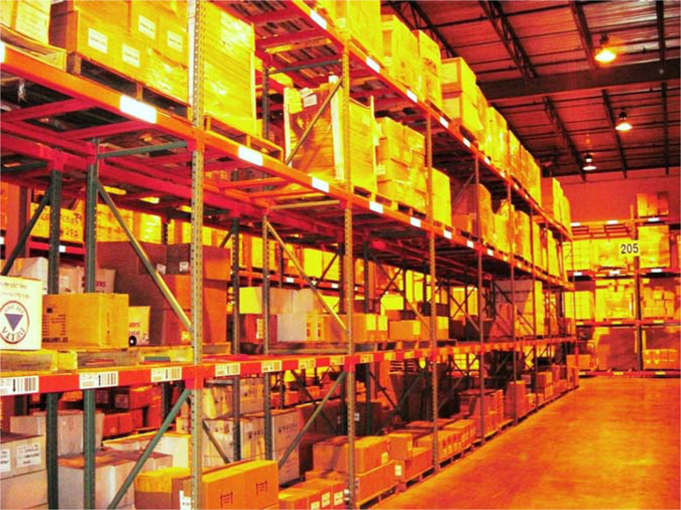
Figure 5.13 Single-deep pallet racks with pallet staging bays (London, England).
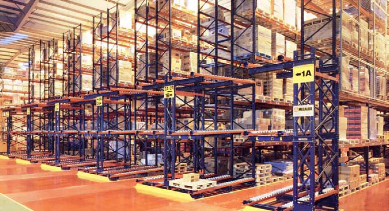
Figure 5.14 Single-deep pallet racks with all-clear aisle lights (Munich, Germany).
The major advantage of single-deep racks is the full access to all unit loads. The major disadvantage is the amount of space devoted to aisles—typically 50 to 60 percent of the available floor space. As a result, in cases where three or more pallets of a SKU are on hand, a storage method that houses at least two pallets perpendicular to the storage aisle may be preferable.
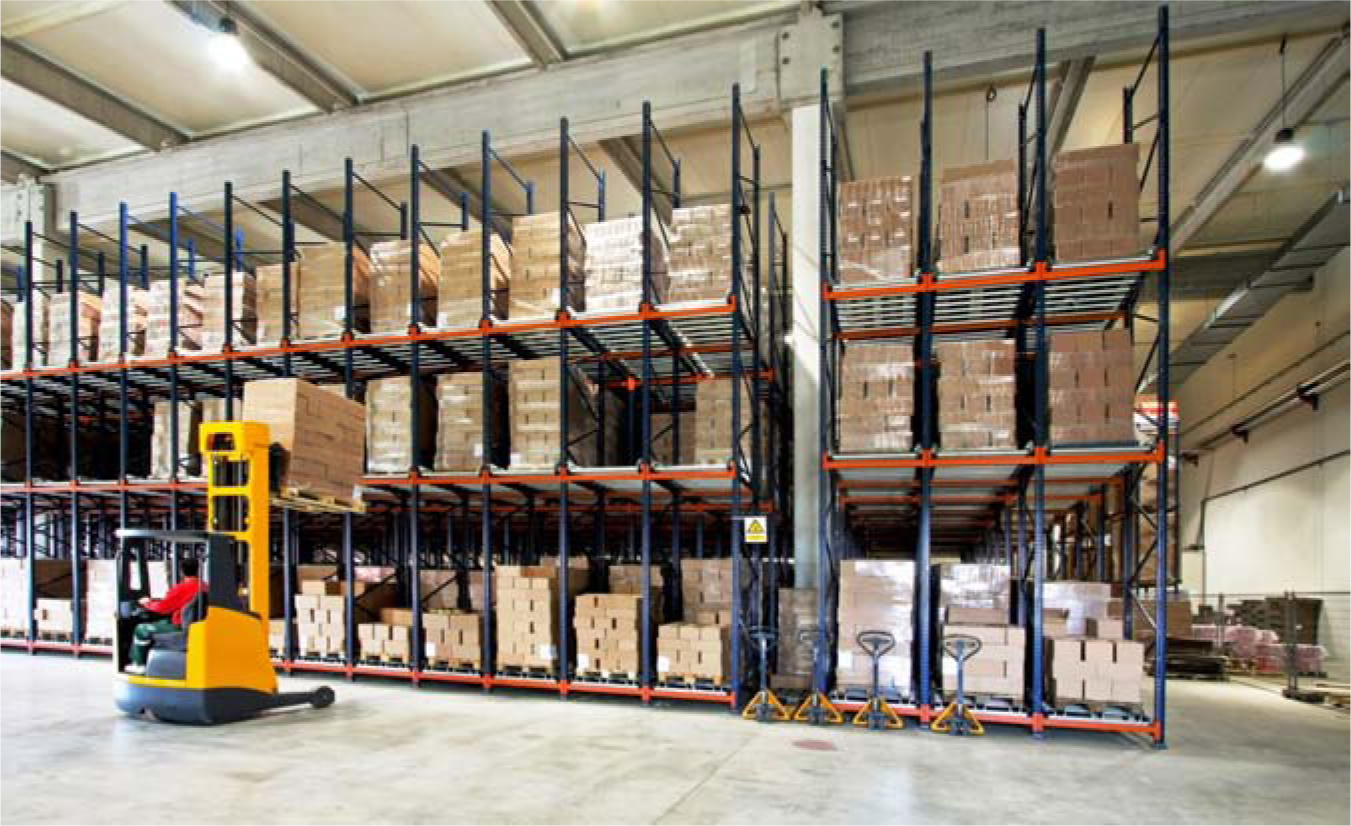
Double-Deep Pallet Racks Double-deep pallet racks are selective racks that are two pallet positions deep (Figure 5.15). The advantage of two-deep rack facings (perpendicular to the aisle) is that less aisle space is required. In most cases, a 50 percent aisle space savings is achieved versus single-deep selective racks.
Figure 5.15 Double-deep pallet racks. (London, England).
Double-deep racks are typically used when the storage requirement for a SKU is three pallets or greater and when product is received and picked frequently in multiples of two pallets. (Assigning SKUs with only a single pallet on hand to double-deep racking is wasteful because one of the two positions in a facing is automatically wasted.) Because pallets are stored two deep, a double-reach forklift or reach truck is required for storage/retrieval (Figure 5.16).
Figure 5.16 Double-deep pallet rack accessed via a double-deep reach truck.
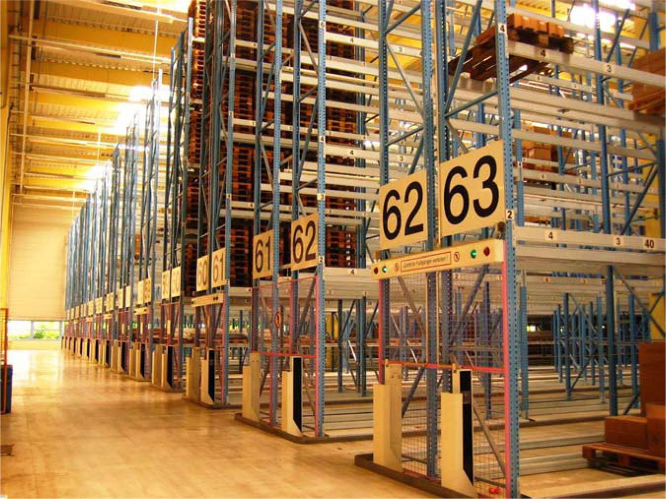
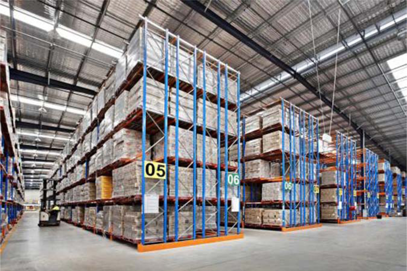
Drive-In/Through Racks Drive-in racks (Figure 5.17) extend the reduction of aisle space begun with double-deep pallet racks by providing storage lanes 5 to 10 loads deep. Drive-in racks allow a reach truck or forklift to drive into the rack to store and retrieve pallets. The rack consists of upright columns with footings as opposed to beams to support pallet storage.
Figure 5.17 Drive-in racks at a Honda parts distribution center.
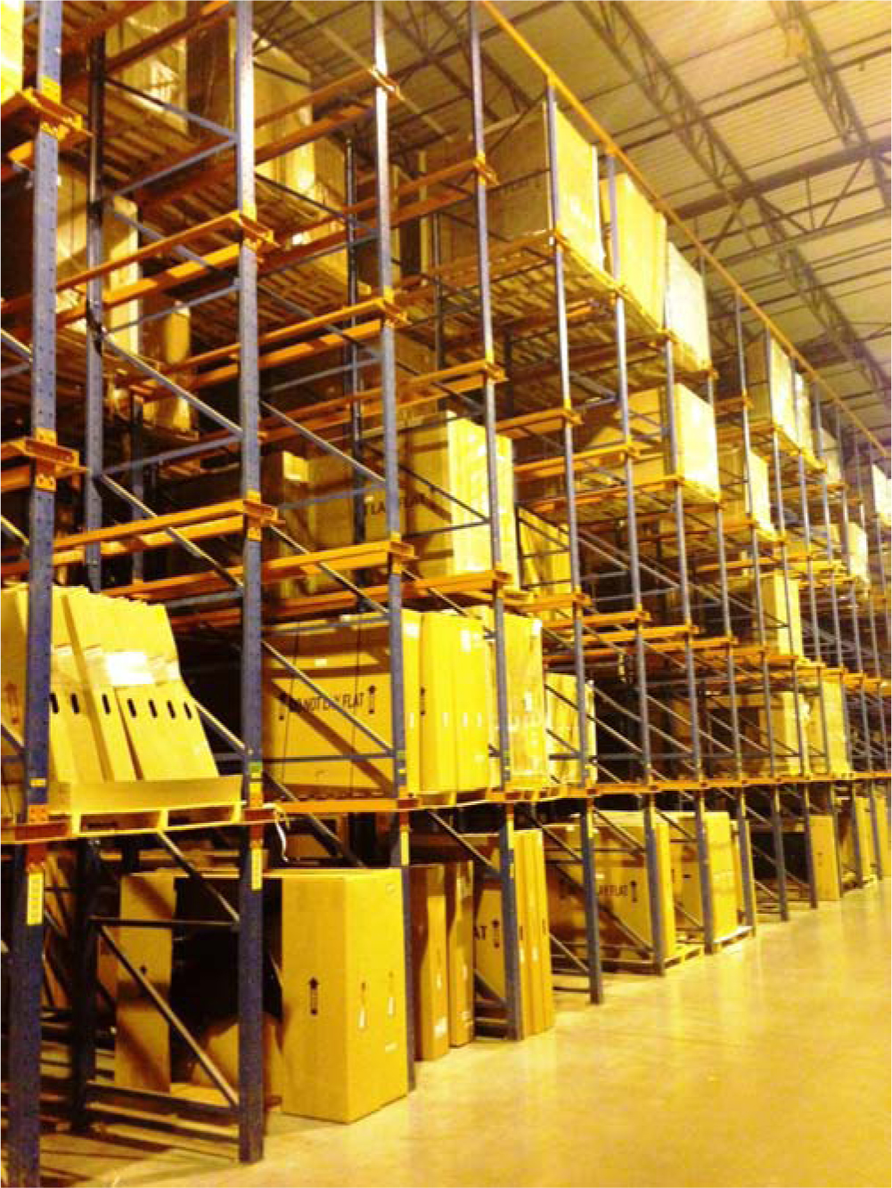
One drawback of drive-in racks is the reduction in vehicle travel speed needed for safe navigation within the confines of the rack. Another drawback is the honeycombing losses because no more than one SKU should be housed in a lane. As a result, drive-in racks are best used for slow- to medium-velocity SKUs with several pallets on hand. As was the case with block stacking, loads are retrieved with a LIFO discipline and with a retrieval approach that frees up each lane as quickly as possible.
Drive-through racks are merely drive-in racks that are accessible from both sides of the rack. These racks are often used for staging loads in a flow-through fashion where a pallet is loaded at one end and retrieved at the other end. The same considerations for drive-in racks apply to drive-through racks.
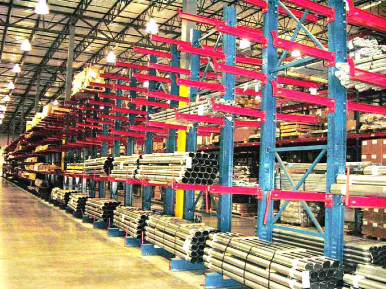
Cantilever Racks Cantilever racks (Figure 5.18) are commonly used to house long objects such as bar stock, lumber, and pallets. They are typically accessed via a side-loader truck.
Figure 5.18 Bar stock in a cantilever rack at Aurora, Indianapolis, Indiana.
Dynamic Racking Systems
Dynamic racking systems are so called because either pallets move within the rack, as is the case with pallet flow racks and pushback racks, or the rack itself moves, as is the case with mobile pallet racks.
Pallet Flow Racks In pallet flow racks (Figures 5.19 through 5.21) loads are conveyed (FIFO) on skate-wheel conveyors, roller conveyors, or rails from the back of a storage lane to the front. As a load is removed from the front of the storage lane, gravity advances the next load to the pick face. The main benefits are high throughput, good space utilization, and the separation of the picking from the replenishment activity. Pallet flow racks are best used for items with high pallet inventory turnover with several pallets on hand.
Figure 5.19 Pallet flow rack (rear view).
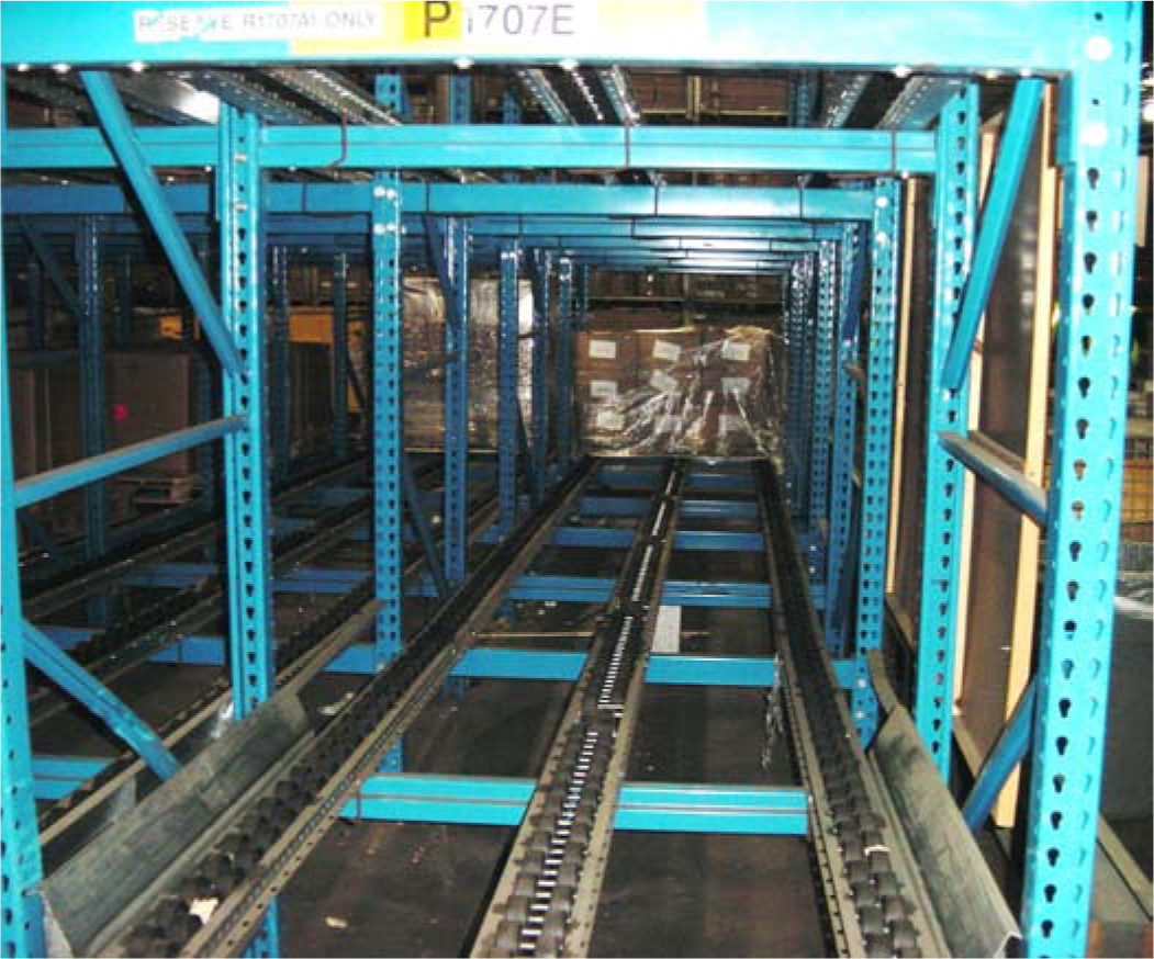
Figure 5.20 Pallet flow rack (new installation).
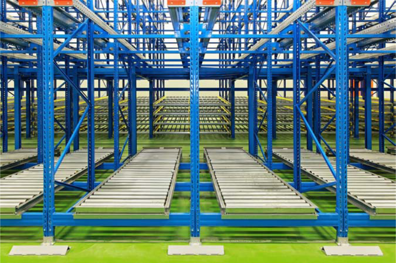
Figure 5.21 Pallet flow rack replenishment.
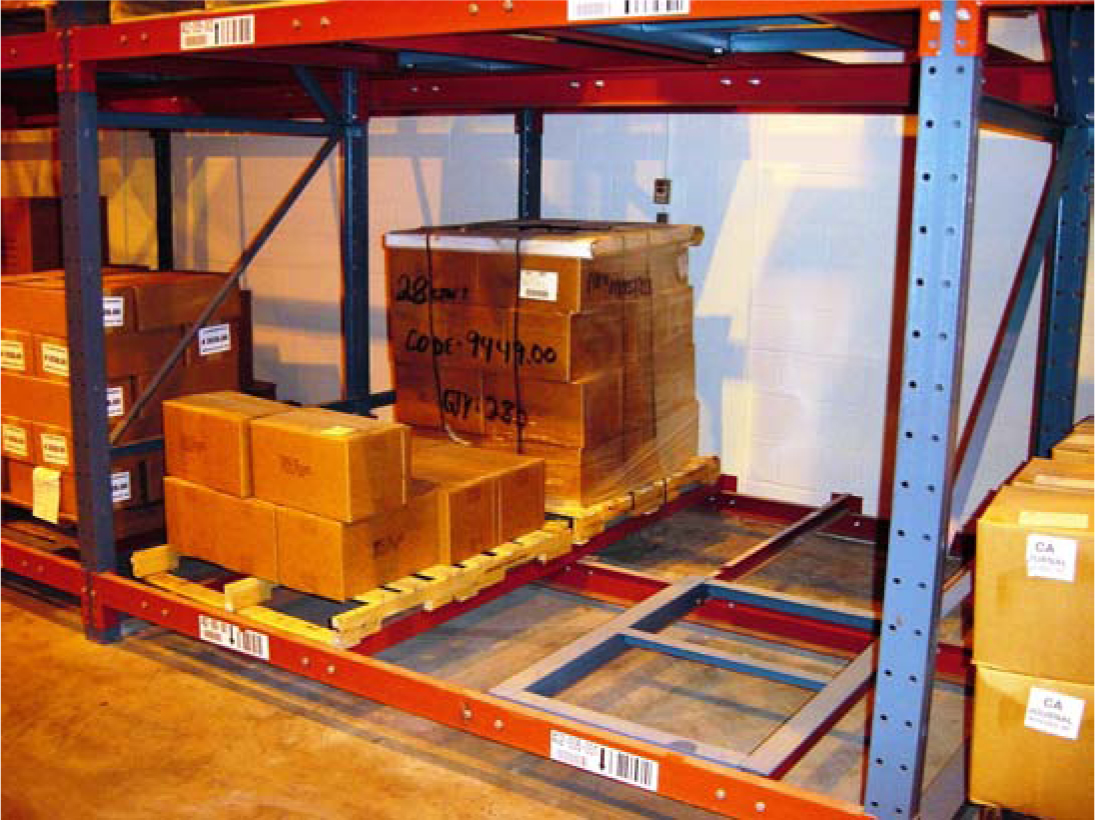
Push-Back Racks Push-back racks (Figures 5.22 and 5.23) provide LIFO deep-lane storage (typically two to five pallets deep) employing a rail-guided carrier for each pallet load. As a load is placed into storage, its weight and the force of the put-away vehicle push the other loads in the lane back into the lane to create room for the additional load. As a load is removed from the front of a storage lane, the weight of the remaining loads gravitationally advances remaining loads to the rack face. Hence, every SKU/lane has a load that is immediately accessible along the aisle. In addition, because all the put-away and retrieval take place at the rack face, there is no need for special lift truck attachments, Push-back racks are appropriate for medium- to fast-moving SKUs with 3 to 10 pallets on hand (Figures 5.22 and 5.23).
Figure 5.22 Push-back racks at a Honda parts distribution center, Georgia.
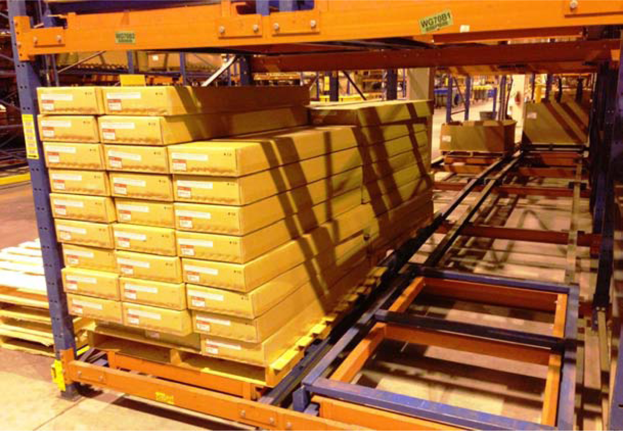
Figure 5.23 Two-deep push-back rack up against at the American Cancer Society’s National Logistics Center, Georgia.
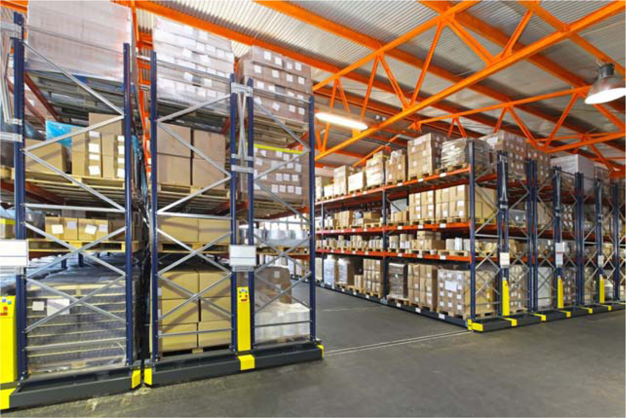
Mobile Pallet Racks Mobile pallet racks (Figures 5.24 and 5.25) are essentially single-deep pallet racks on wheels or tracks permitting aisles to be created on-demand when are where they are needed. Aisles are created by moving (mechanically or manually) the adjacent row and creating an aisle in front of the desired row. As a result, less than 10 percent of floor space is devoted to aisles, and storage density is the highest of any of the pallet storage alternatives. Unfortunately, pallet-retrieval productivity is the lowest of any of the alternatives we have considered. Hence mobile racks are justifiable when space is scarce and expensive and for slow-moving SKUs with one to three pallets on hand.
Figure 5.24 Mobile pallet racks are most easily justified in situations where occupancy costs are extremely high and throughput requirements are fairly low, as is the case at Scroll’s slow-mover’s warehouse. (Tokyo, Japan)
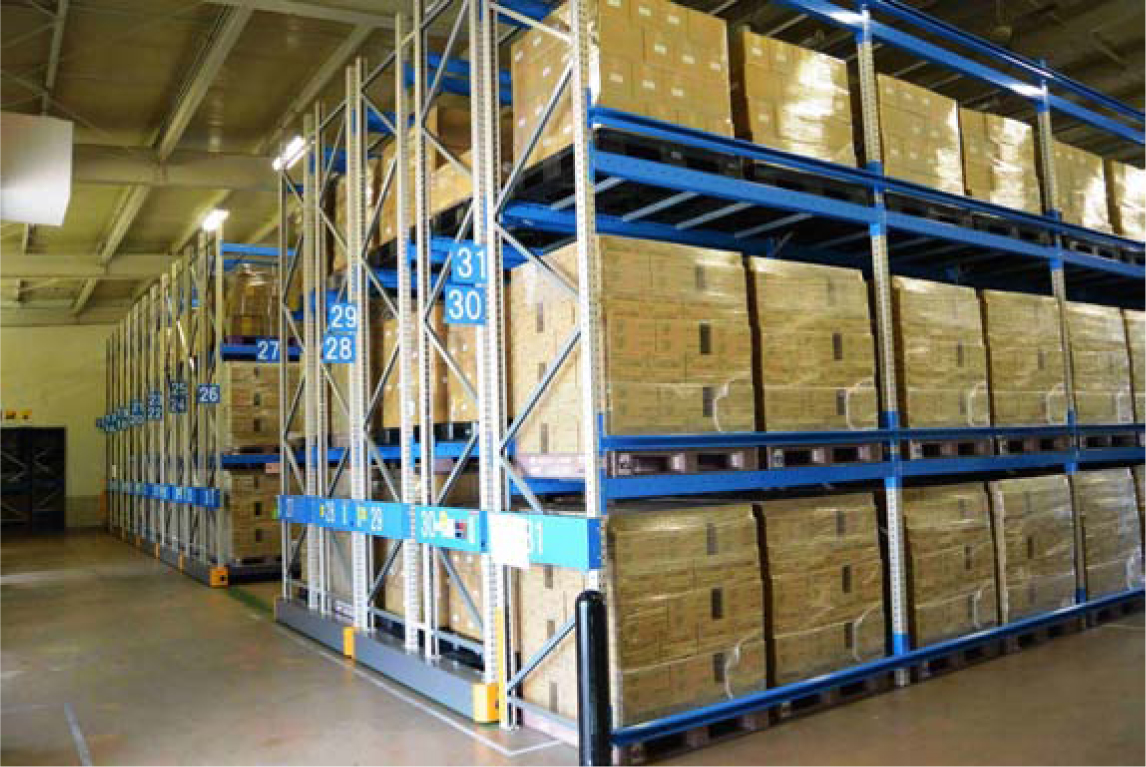
Figure 5.25 Mobile pallet rack installation.
Pallet Storage System Selection
The key to selecting the appropriate pallet storage system is to assign each SKU to a pallet storage system whose storage and productivity characteristics match the activity and inventory profile of the SKU. Table 5.1 summarizes the key features of each pallet storage system, including storage density, load accessibility, throughput capacity, inventory and location control, FIFO maintenance, load size variability, and ease of installation.
Table 5.1 Pallet storage system comparison.
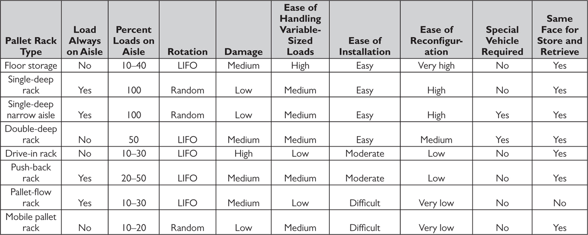
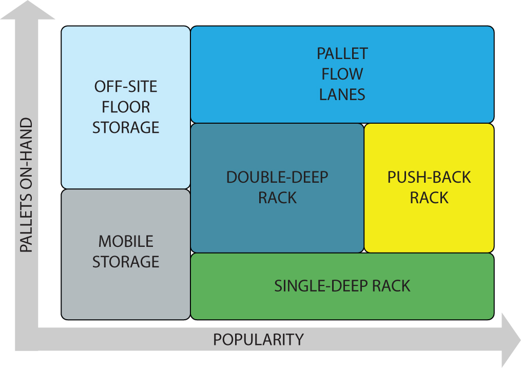
Figure 5.26 illustrates an example pallet storage mode analysis. The example is taken from a particular case and cannot be generalized because the preference regions vary widely as a function of the cost and availability of labor and space. The analysis indicates the most economically appropriate assignment of popularity-inventory families to pallet storage modes.
Figure 5.26 Example pallet storage mode optimization for a large grocer.
5.2 Pallet Handling Systems
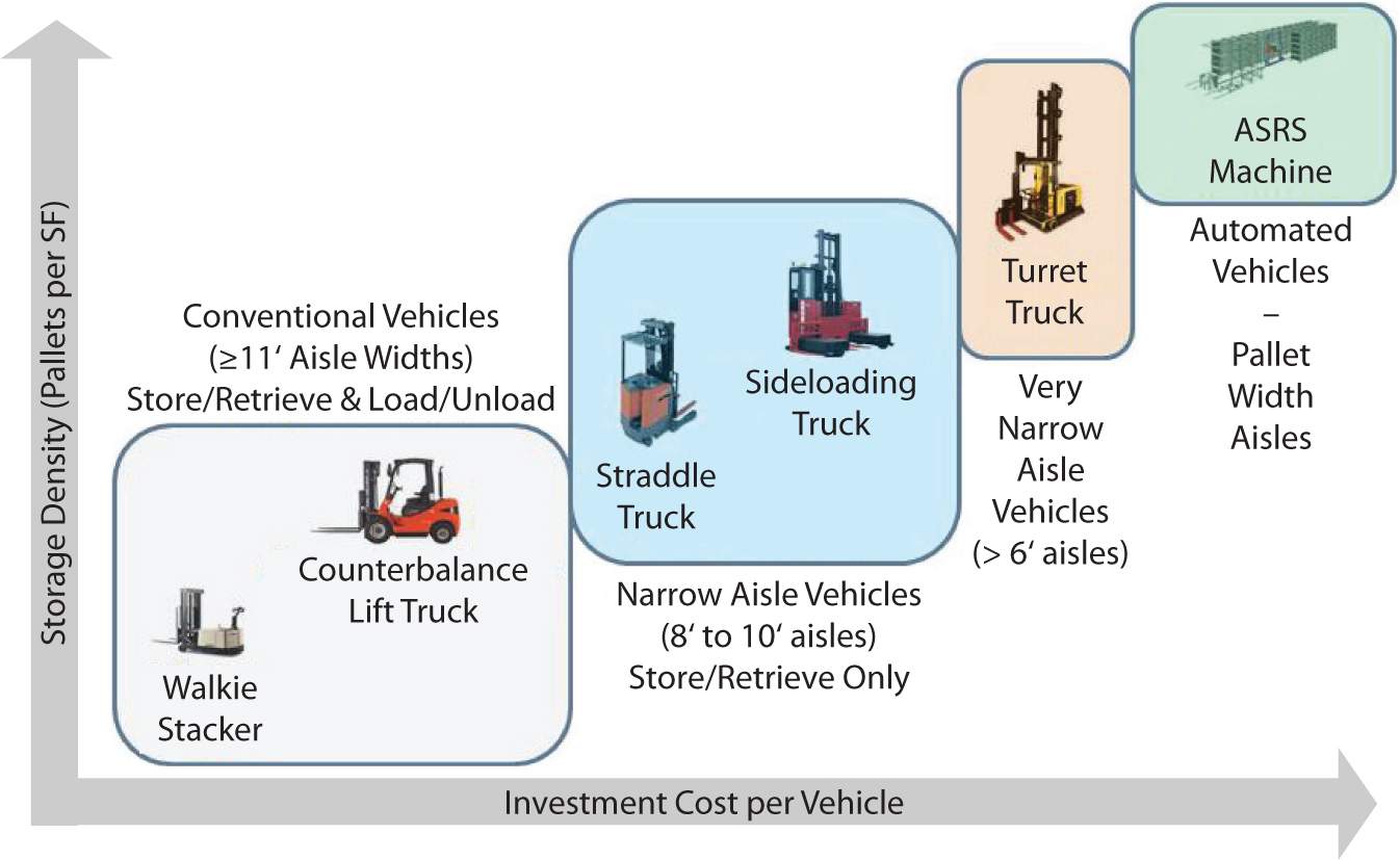
In rank order from least to most expensive and simplest to most complex, the most popular pallet handling systems (Figure 5.27) include
Figure 5.27 Pallet handling systems comparison.
![]() Conventional vehicles
Conventional vehicles
![]() Walkie stackers
Walkie stackers
![]() Counterbalance lift trucks
Counterbalance lift trucks
![]() Sit-down counterbalance lift trucks
Sit-down counterbalance lift trucks
![]() Stand-up counterbalance lift trucks
Stand-up counterbalance lift trucks
![]() Driverless counterbalance lift trucks
Driverless counterbalance lift trucks
![]() Straddle trucks
Straddle trucks
![]() Straddle reach trucks
Straddle reach trucks
![]() Side-loader trucks
Side-loader trucks
![]() Very narrow-aisle vehicles
Very narrow-aisle vehicles
![]() Turret trucks
Turret trucks
![]() Swing-fork turret trucks
Swing-fork turret trucks
![]() Swing-mast turret trucks
Swing-mast turret trucks
![]() Hybrid trucks
Hybrid trucks
![]() Automated vehicles
Automated vehicles
![]() Automated storage and retrieval machines
Automated storage and retrieval machines
![]() Automated guided storage and retrieval vehicles
Automated guided storage and retrieval vehicles
The applications, pros and cons, and related costs of each system are described next.
Conventional Vehicles
Walkie stackers and counterbalance lift trucks make up the class of conventional pallet handling systems.
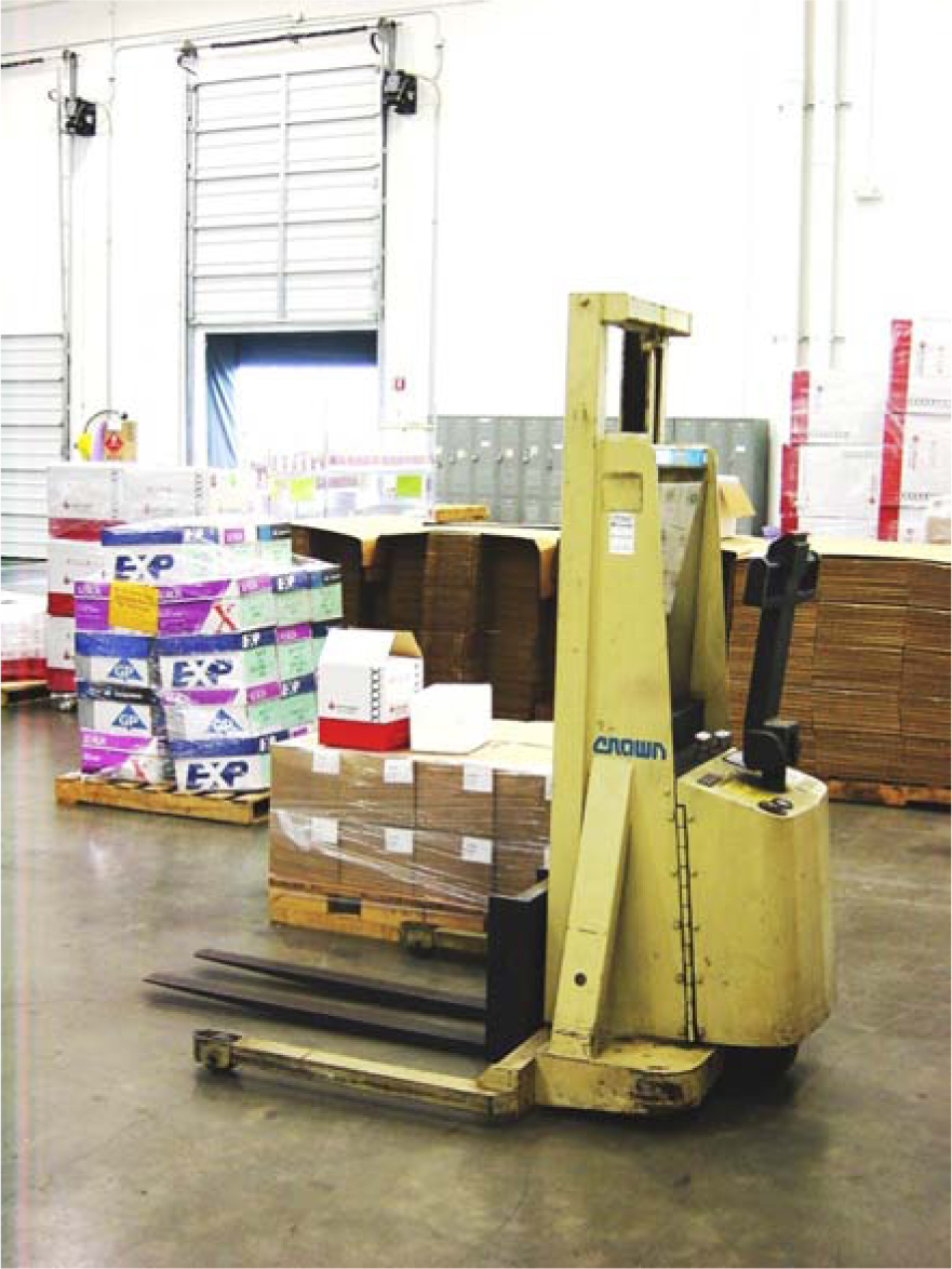
Walkie Stackers A walkie stacker (Figure 5.28) lifts, transports, and stacks. An operator steers from a walking position behind the vehicle. Where there is low throughput, short travel distances, and low storage height, and a low-cost solution is desired, Walkie stackers are appropriate. A typical walkie stacker can stack loads a maximum of three loads high and offers the dual purpose (no handoff required) of pallet retrieval/put-away and truck loading/unloading.
Figure 5.28 Walkie stacker in receiving operations for a large biotech firm.
Counterbalance Lift Truck As the name implies, counterbalance lift trucks (Figures 5.29 through 5.33) employ a counterbalance in the back of the truck to stabilize loads carried and lifted on a mast in the front of the truck. Besides forks, other attachments may be used to lift unique load configurations. The lift height limitation is around 25 feet. Counterbalance trucks are available with operating capacities of up to 100,000 pounds.
Figure 5.29 Sit-down counterbalance lift truck.

Figure 5.30 Stand-up counterbalance lift truck Georgia.
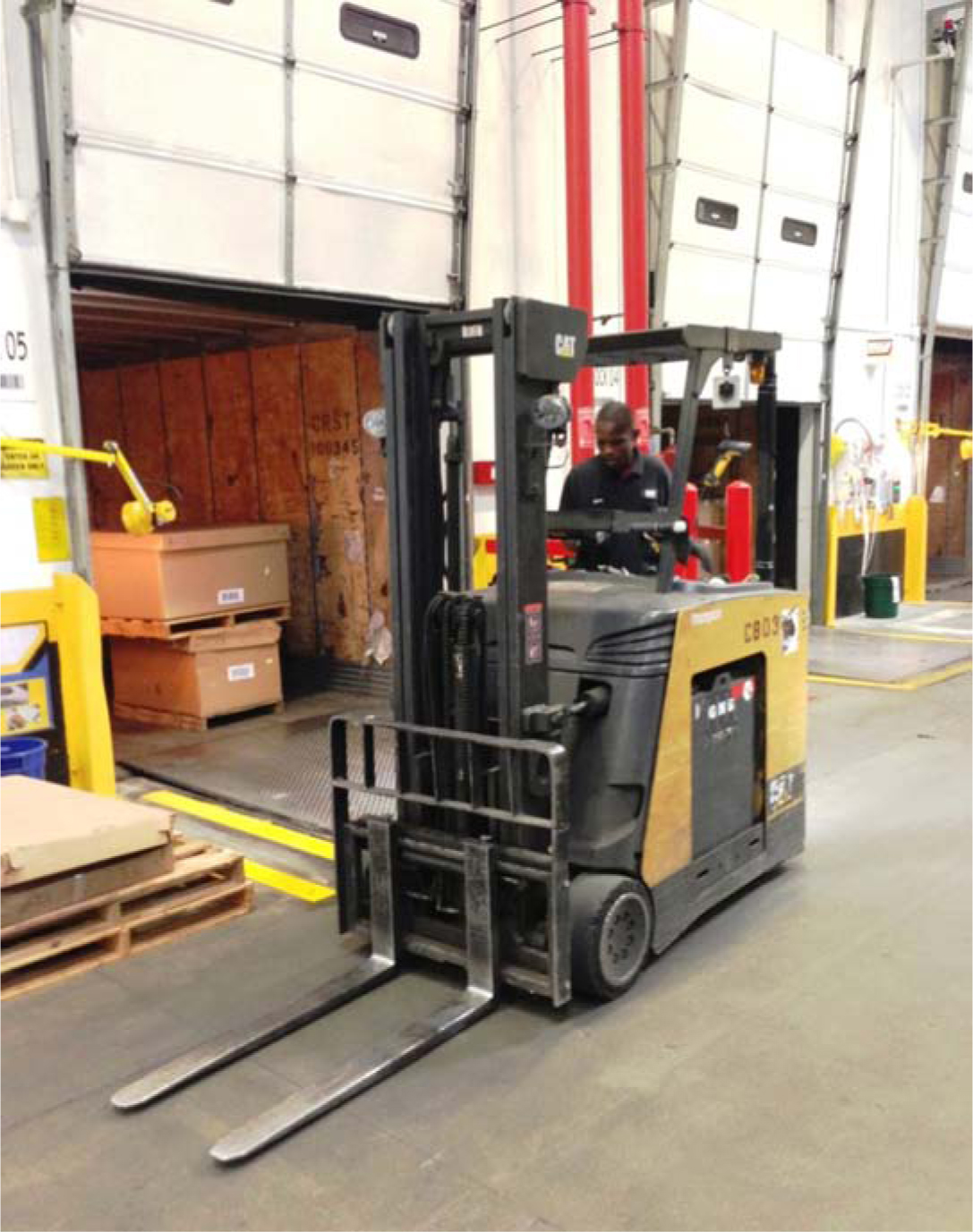
Figure 5.31 Sit-down counterbalance lift truck with ram attachment Georgia.
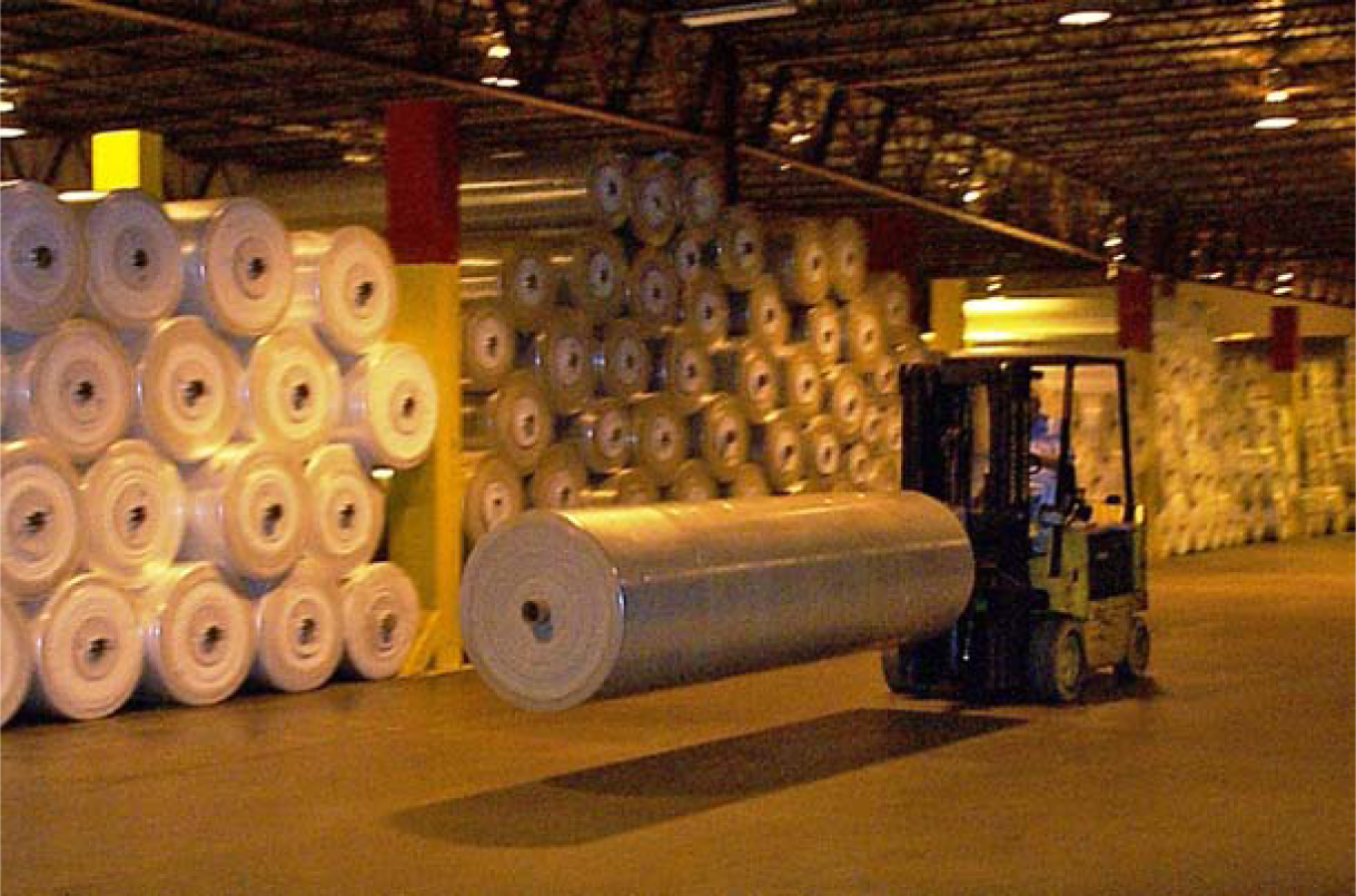
Figure 5.32 Stand-up counterbalance lift truck at NTT (Tokyo, Japan).
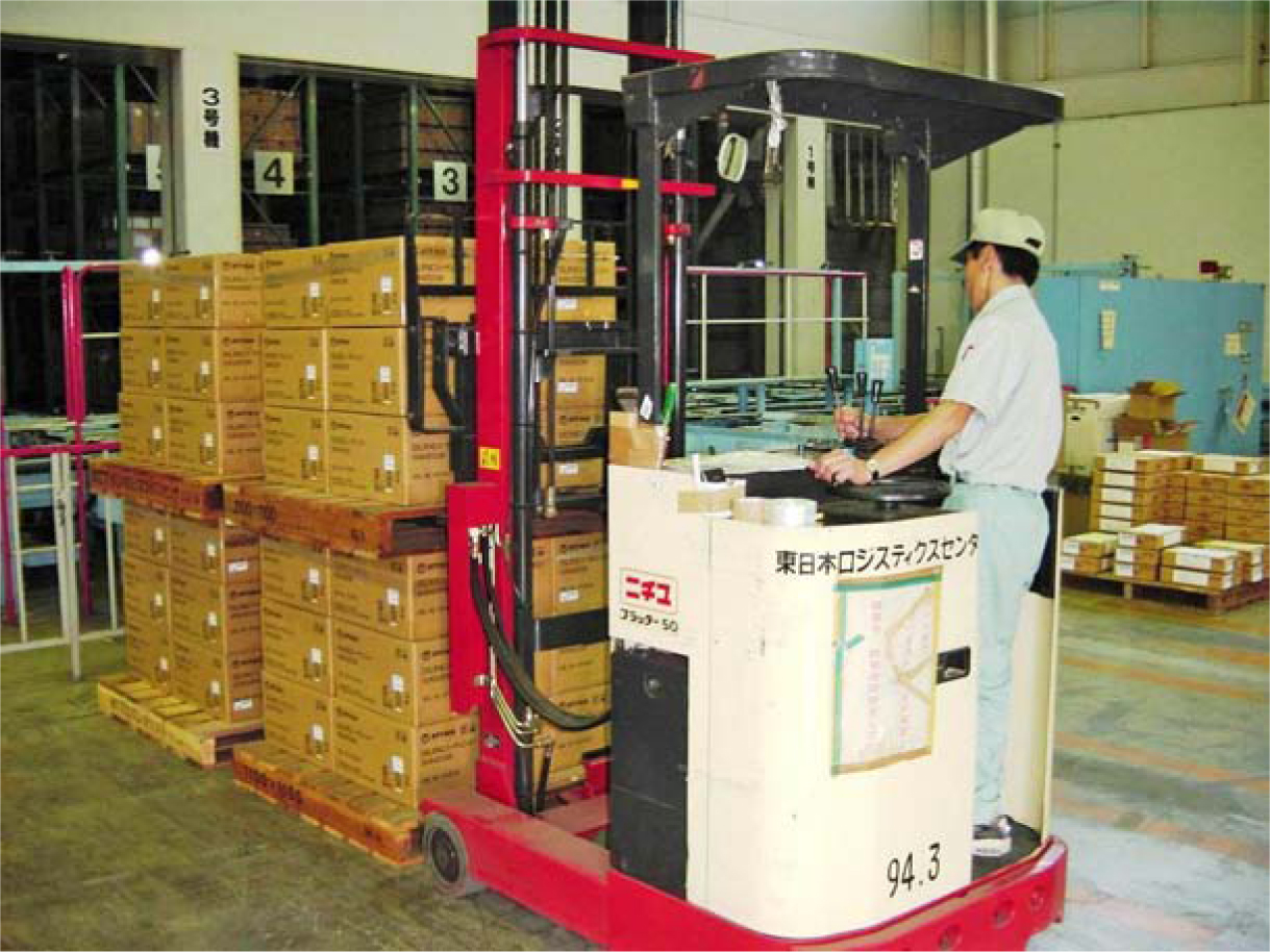
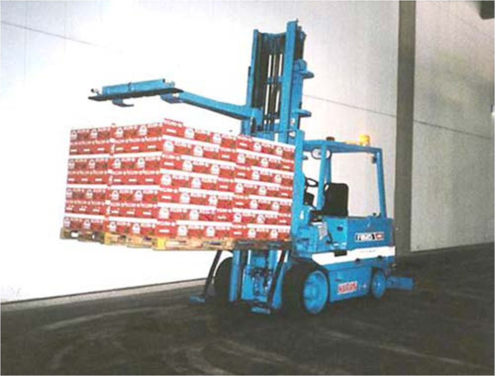
Figure 5.33 Multiload counterbalance truck at Suntory (Nagoya, Japan).
Because the operator rides (seated, or standing in the case of stand-up counterbalance trucks) on the vehicle, counterbalance trucks can be used for longer moves than walkie stackers. Counterbalance trucks also offer the flexibility to retrieve/put away a pallet and load/unload a truck in the same move. This flexibility, coupled with the vehicle’s relatively low cost, makes the counterbalance lift truck the benchmark for all other pallet-retrieval vehicles. Multiload counterbalance trucks (Figure 5.33) can be used to increase the overall productivity of lift truck operations.
The major drawback of counterbalance lift trucks is its wide turning radius. As a result, an 11- to 12-foot storage aisle width is typically required.
The aisle width requirement is the justification focus of alternative vehicles. As we proceed through the remaining list, the vehicles operate in progressively narrower aisles (hence the reference to narrow-aisle vehicles) and progressively taller reach heights. At the same time, the vehicles are progressively more expensive, and none offers the retrieval/put-away and load/unload flexibility that the counterbalance truck offers. Hence the incremental space cost savings must be sufficient to pay for the incremental vehicle cost and loss of handling flexibility.
Narrow-Aisle Vehicles
Straddle trucks, straddle reach trucks, and side-loader trucks are classified as narrow-aisle vehicles.
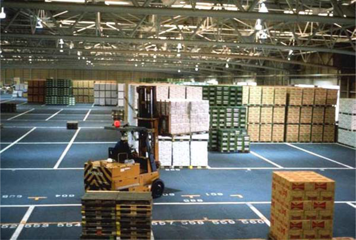
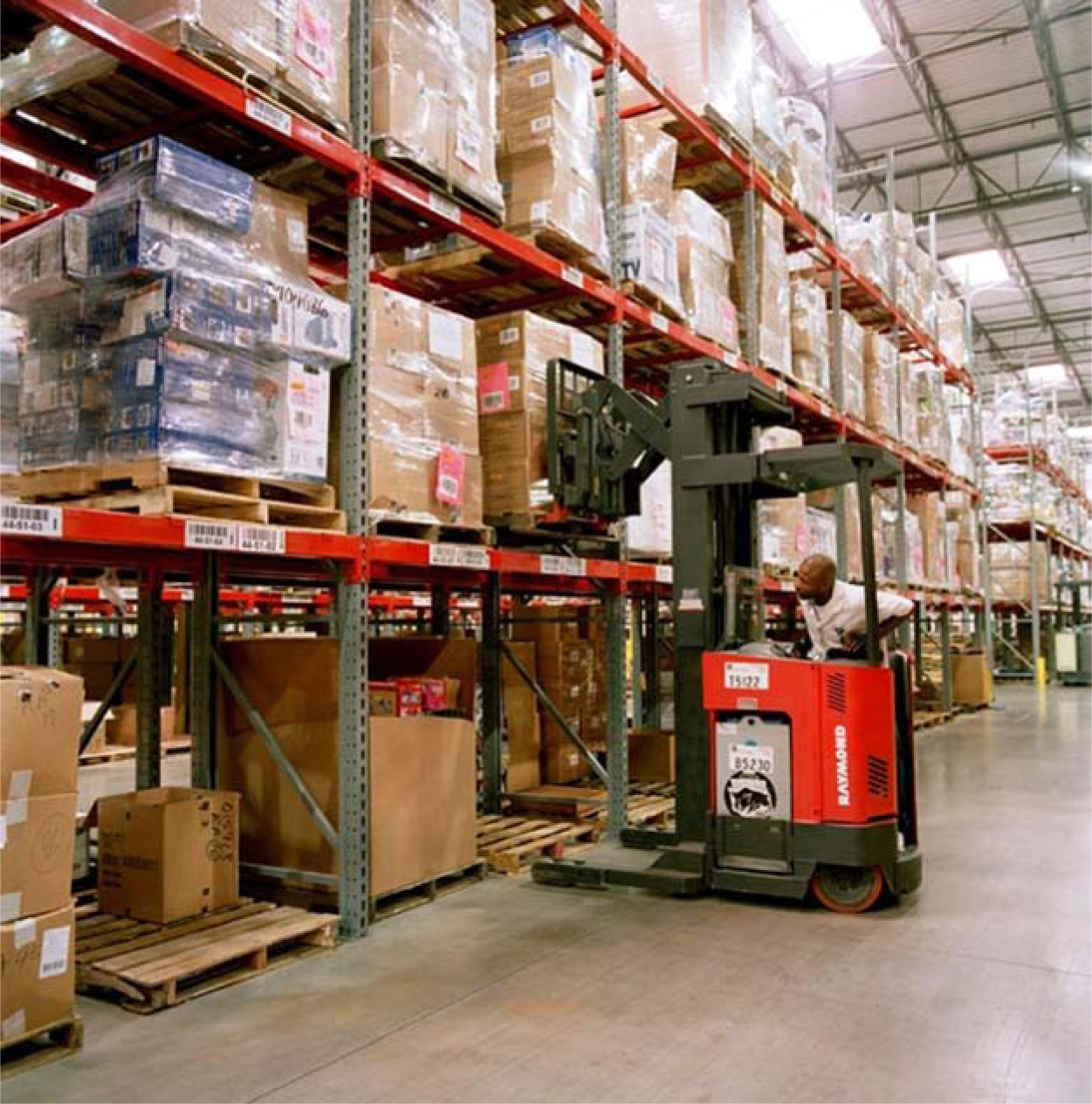
Straddle Trucks A straddle truck (Figures 5.34 and 5.35) provides load and vehicle stability using outriggers to straddle the pallet load instead of a counterbalanced weight. As a result, the aisle width requirement is 8 to 10 feet as opposed to the 11 to 12 feet required by a counterbalance truck. To access loads in storage, the outriggers are driven into the rack, allowing the mast to come flush with the pallet face. Hence it is necessary to support the floor-level load on rack beams.
Figure 5.34 Straddle truck in a Caterpillar DC. Georgia.
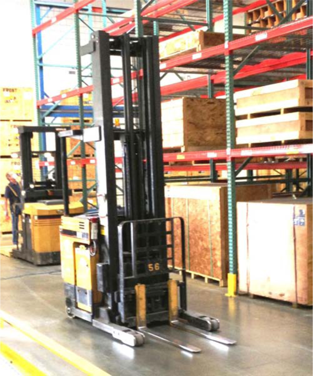
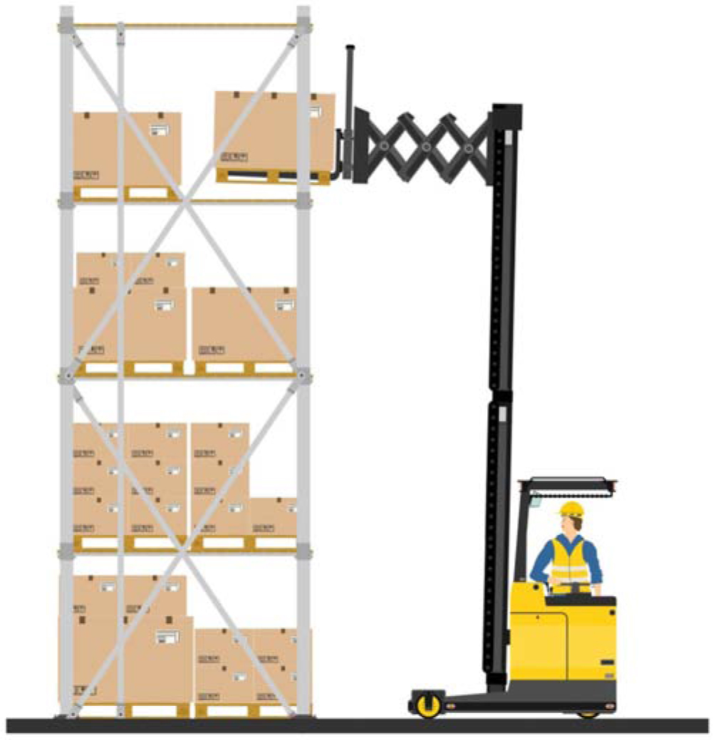
Straddle Reach Trucks Straddle reach trucks (Figures 5.36 and 5.37) were developed from conventional straddle trucks by shortening the outriggers on the straddle truck and attaching a scissors reach mechanism. In so doing, the outriggers do not have to be driven under the floor-level load to allow access to the storage positions. Hence no rack beams are required at floor level, conserving rack cost and vertical storage space.
Figure 5.36 Straddle reach truck.
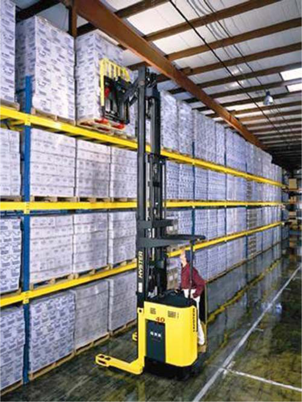
Figure 5.37 Straddle reach truck in a Sear’s DC Georgia.
Side-Loading Trucks A side-loading truck (Figure 5.38) loads and unloads from one side, thus eliminating the need to turn in an aisle to access storage positions. There are two basic side-loader designs. Either the entire mast moves on a set of tracks transversely across the vehicle, or the forks project from a fixed mast on a pantograph.
Figure 5.38 Side-loading truck.

A typical aisle would be 6½ feet wide, rail or wire-guided. Side loaders generally can access loads up to 40 feet high.
The major drawback of a side-loading truck is the need to enter the correct end of the aisle to access a particular location, thus adding to the time and complexity involved in truck routing.
The vehicle’s configuration particularly lends itself to storing long loads in cantilever racks.
Very Narrow-Aisle Vehicles
Turret trucks and hybrid storage retrieval vehicles are classified as very narrow-aisle vehicles.
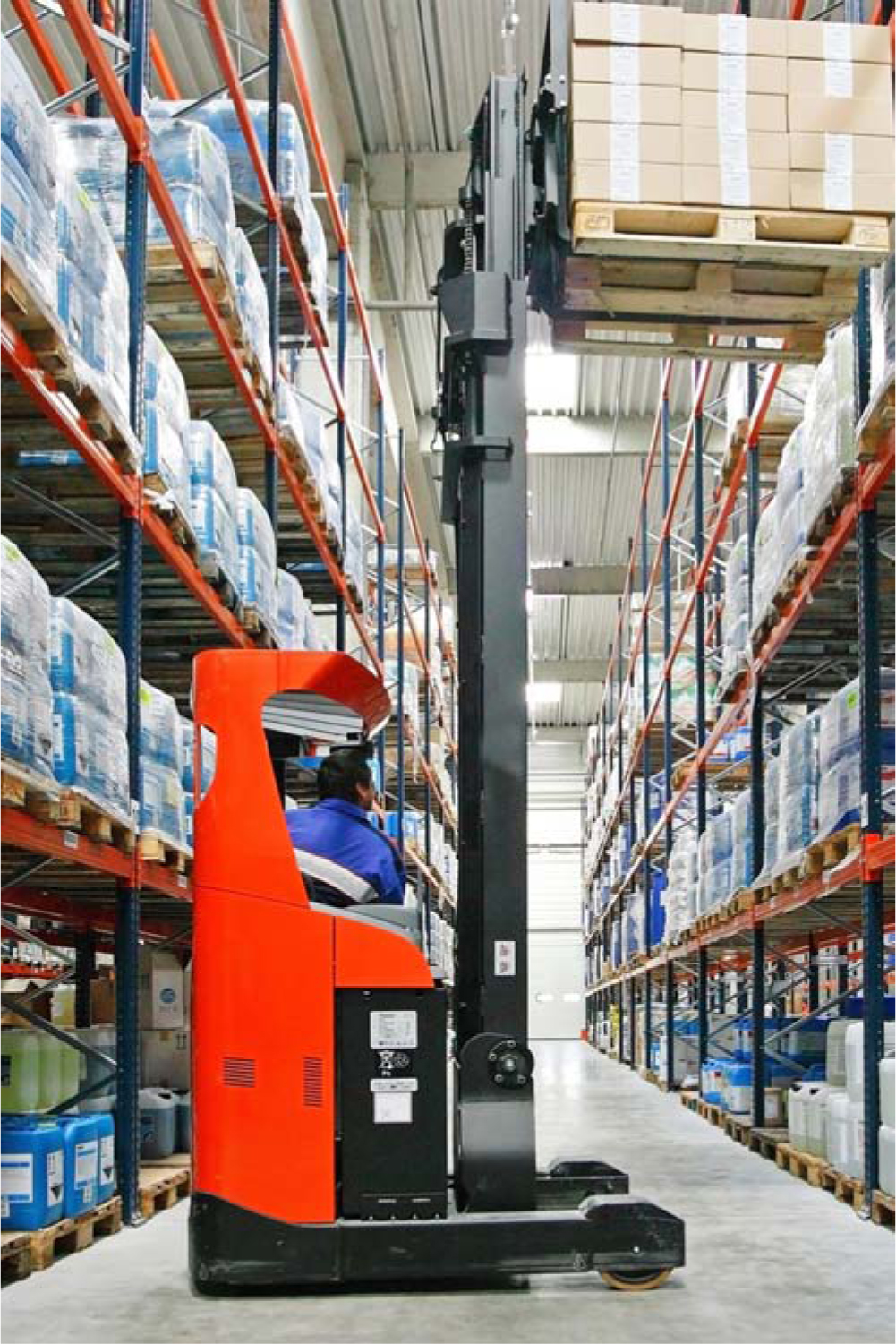
Turret Trucks Turret trucks (Figures 5.39 and 5.40) do not require the vehicle to make a turn within the aisle to store or retrieve a pallet. Rather, the load is lifted either by forks that swing on the mast, a mast that swings from the vehicle, or a shuttle fork mechanism.
Figure 5.39 Wire-guided turret truck in a Verizon distribution center Georgia.
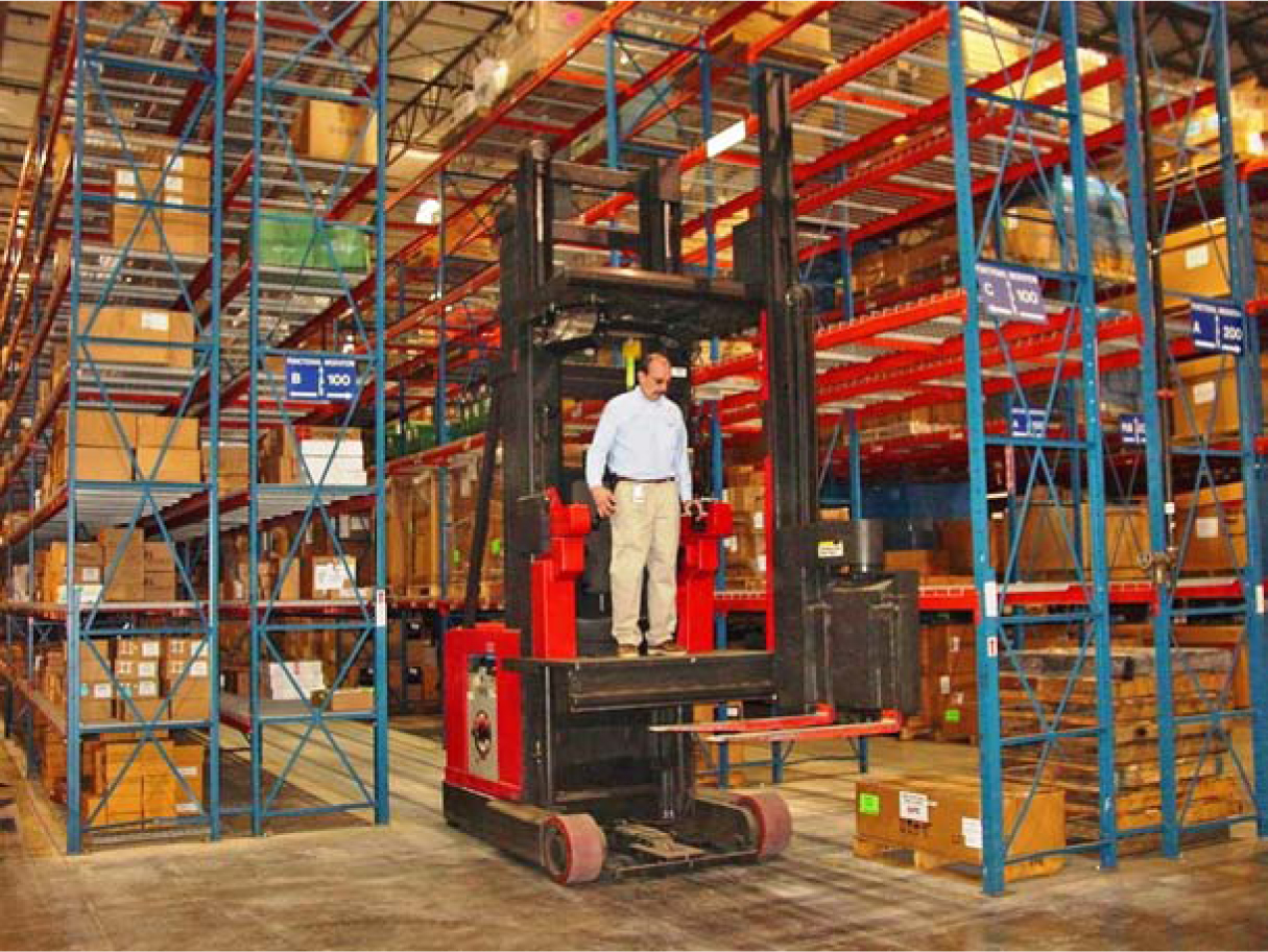
Figure 5.40 Counterbalance turret trucks operate in very narrow aisles and are a hybrid of a traditional counterbalance lift truck with a turret front end. They are less expensive than conventional turret trucks but cannot operate at the reach height of conventional turret trucks.
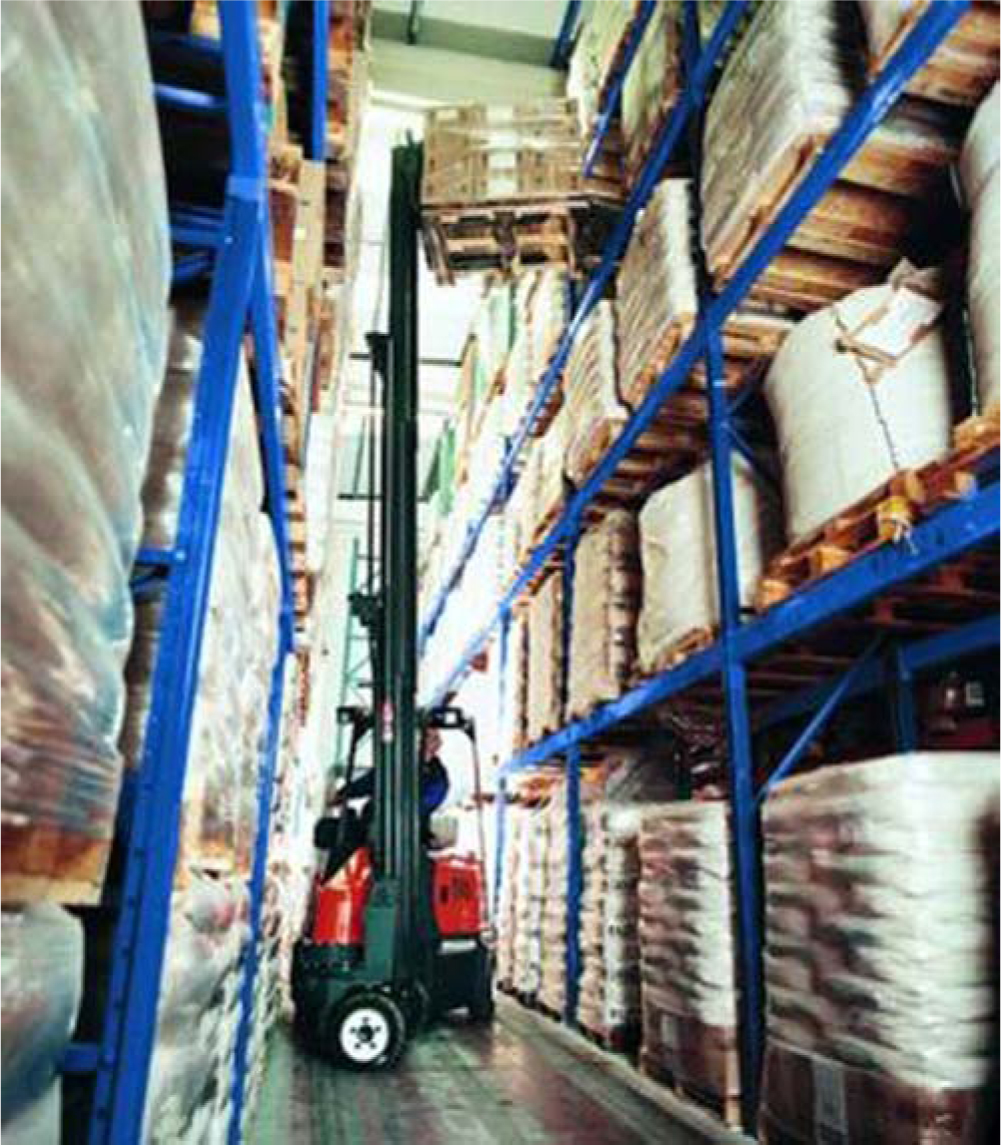
Turret trucks provide access to load positions at heights up to 50 feet, and operate in aisles 5 or 6 feet wide, further increasing storage density. Turret trucks generally have good maneuverability outside aisles, and some with telescoping masts may be driven into trailers. The vehicle may be wire or rail guided.
Hybrid Storage/Retrieval Vehicles A hybrid storage/retrieval vehicle (Figure 5.41) evolved from the design of an automated storage and retrieval machine used in automated storage/retrieval systems. Unlike the automated machine, the hybrid truck is not captive to an aisle but may leave one aisle and enter another. Present models are somewhat clumsy outside aisles, but they operate within aisles at a high throughput rate.
Figure 5.41 Hybrid storage/retrieval truck at the U.S. Defense Logistics Agency Pennsylvania.
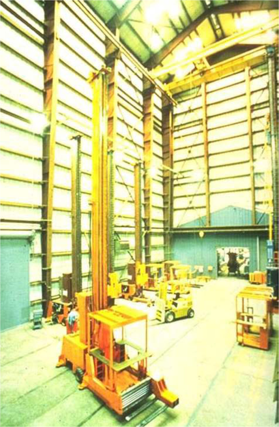
Hybrid storage/retrieval vehicles operate in aisle widths ranging from 5 to 7 feet and access rack storage up to 60 feet high in a rack-supported building. The lack of flexibility, the high capital commitment, and the high dimensional tolerance in the rack are the disadvantages of hybrid storage/retrieval vehicles.
Automated Vehicles
Automated pallet handling systems include automated storage and retrieval systems (ASRSs) and automated guided storage and retrieval vehicles (AGSRVs).
Automated Storage/Retrieval Systems An automated storage/retrieval system (Figures 5.42 through 5.45) for pallets is commonly referred to as a unit-load ASRS. It is defined by The Material Handling Institute as a storage system that uses fixed-path storage and retrieval machines running on one or more rails between fixed arrays of storage racks (Figures 5.42 through 5.45).
Figure 5.42 Automated storage and retrieval systems in Argos’ London distribution center.
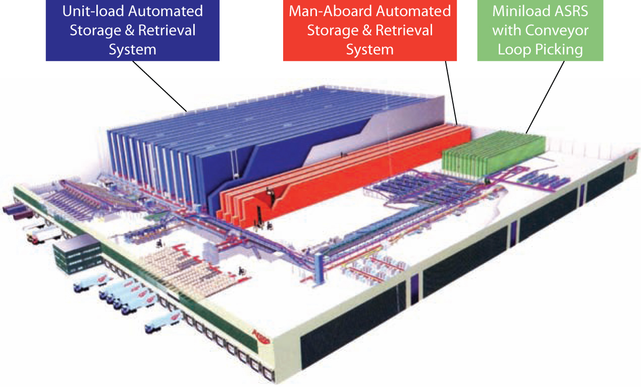
Figure 5.43 ASRS input-output front end in a Netto warehouse (Copenhagen, Denmark).
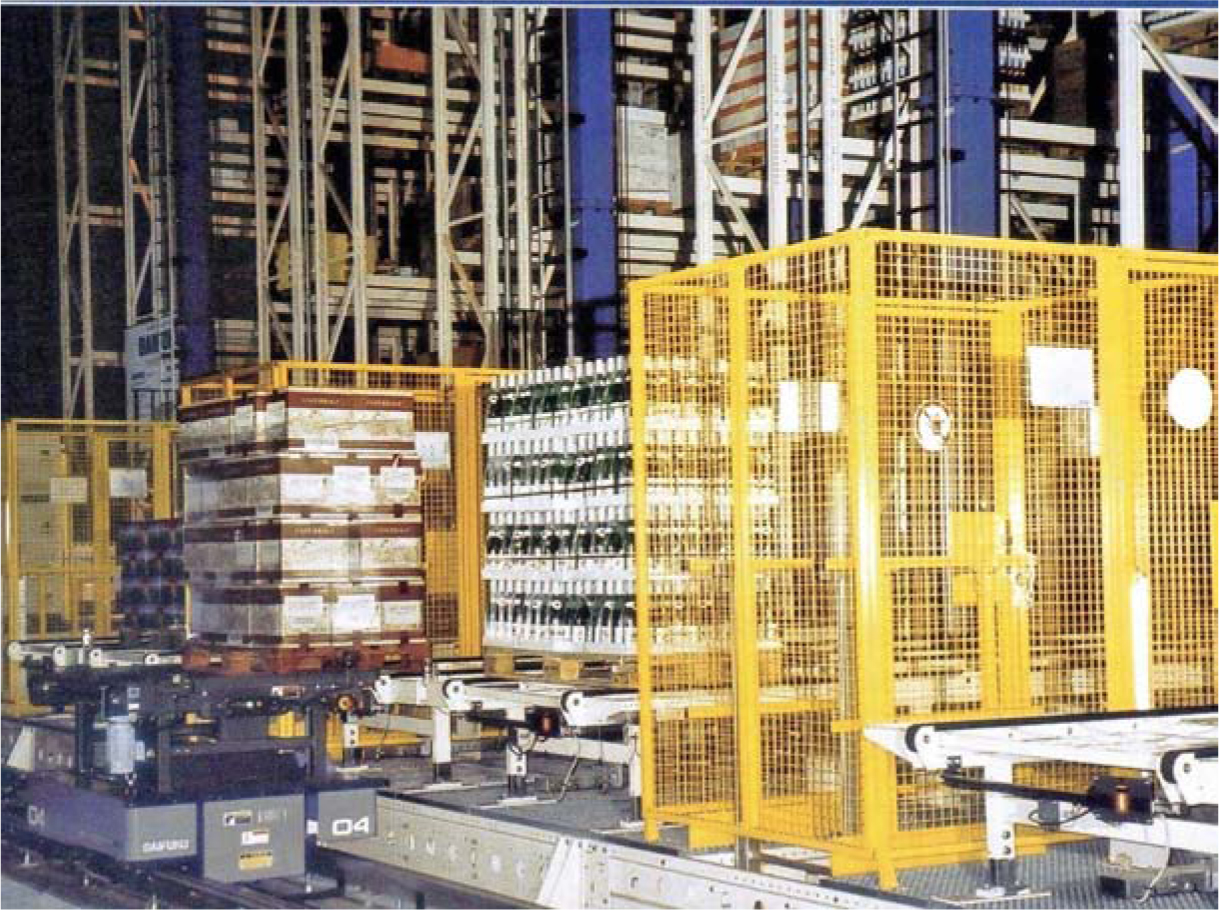
Figure 5.44 Rack-supported ASRS building at Rittal, Ohio.
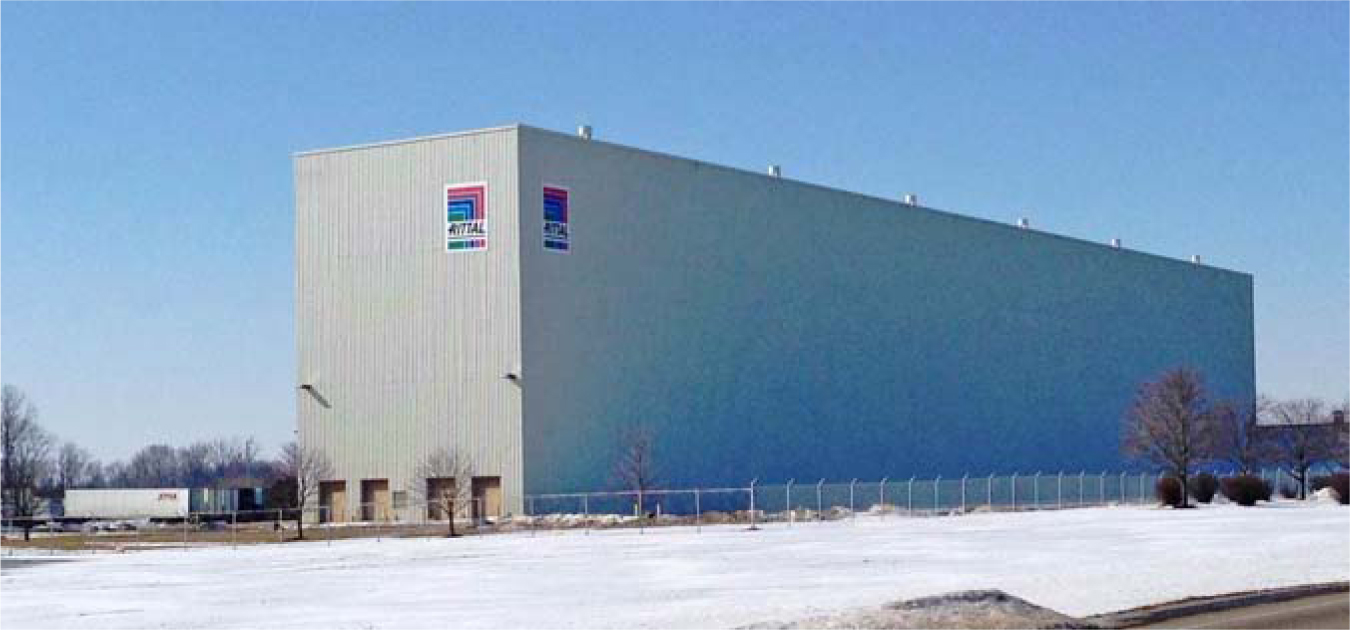
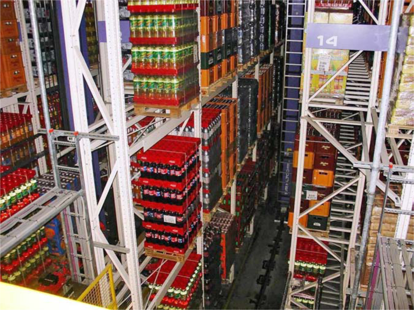
Figure 5.45 A peek down the aisle of a pallet automated storage and retrieval system.
A unit-load ASRS usually handles loads in excess of 1,000 pounds and is used for raw materials, work-in-process, and finished goods. A typical ASRS operation has the storage/retrieval machine picking up a load at the front of the system, transporting the load to an empty location, depositing the load in the empty location, and returning empty to the input-output (I/O) point. These single command operations accomplish either a storage OR a retrieval between successive visits to the I/O point. A dual command has the storage/retrieval machine picking up a load at the I/O point, traveling loaded to an empty location (typically the closest empty location to the I/O point), depositing the load, traveling empty to the location of the desired retrieval, picking up the load, traveling loaded to the I/O point, and depositing the load. In a dual-command operation, two operations, a storage and a retrieval, are accomplished between successive visits to the I/O point.
A unique feature of storage/retrieval machine travel is that vertical and horizontal travel occurs simultaneously. Consequently, the time to travel to any destination in the rack is the maximum of the horizontal and vertical travel times required to reach the destination from the origin.
The typical unit-load ASRS configuration, if there is such a thing, would include unit loads stored one deep (i.e., single deep) in long, narrow aisles, each of which contains a single storage/retrieval machine. The one I/O point would be located at the lowest level of storage and at one end of this system.
More often than not, one of the parameters defining the system is atypical. The possible variations include the depth of storage, the number of storage and retrieval machines assigned to an aisle, and the number and location of I/O points.
Automated Guided Storage/Retrieval Vehicles Automated guided storage/retrieval vehicles are essentially driverless counterbalance trucks (Figures 5.46 and 5.47). Automated storage/retrieval vehicles receive communication through and run on a grid of wires buried a fraction of an inch beneath the surface of the warehouse floor. Automated storage/retrieval vehicles are rare but can be justified when wage rates are high, when labor is scarce, and when move rates are high and stable, over predictable paths.
Figure 5.46 Automated storage/retrieval vehicle.
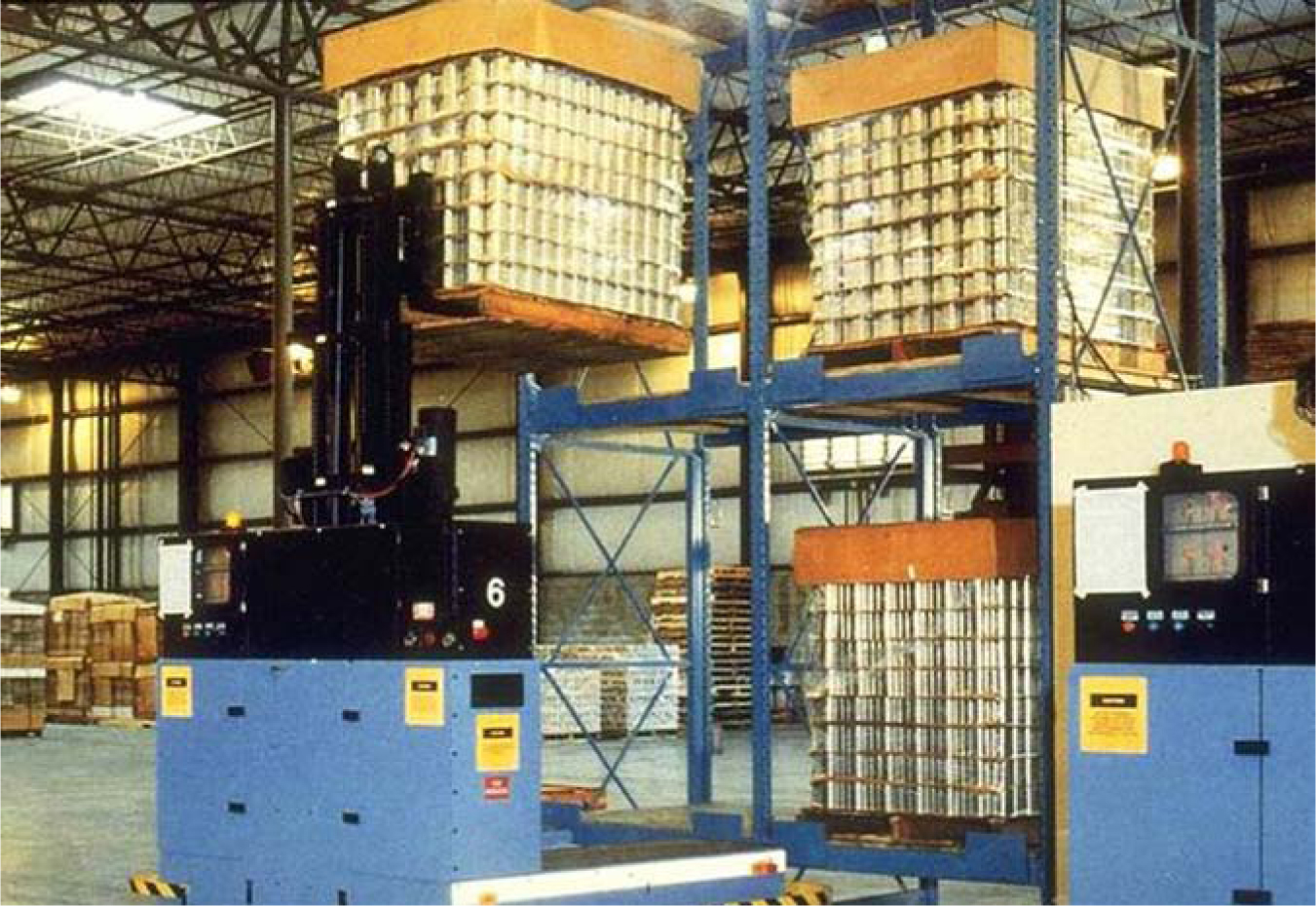
Figure 5.47 Driverless counterbalance lift truck at Kirin (Osaka, JAPAN).
Pallet Handling Systems Comparison and Selection
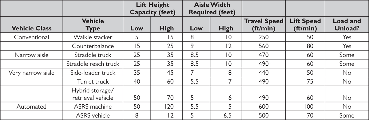
Table 5.2 presents a summary comparison of the key features of pallet handling systems.
Table 5.2 Pallet Handling Systems Comparison.
5.3 Pallet Storage and Handling Systems Selection
Pallet storage and retrieval systems should be selected in conjunction with one another to provide high-storage density and high storage/retrieval throughput capacity. Because each item has unique demand and dimensional profiles, and because each storage/retrieval system provides different storage/handling capabilities, the key is to optimally determine the proper storage/retrieval combination for each item. To assist our clients in making this determination, we developed the RightStore Pallet Optimization, which computes the lowest cost storage/retrieval alternative for each item in the warehouse, taking into consideration the cost of space, labor, racking, and equipment. An example analysis from a recent client engagement is provided in Figure 5.48. The RightStore™ solution yielded $847,000 in annual savings; a 28% reduction in total storage cost.
Figure 5.48 This RightStore pallet optimization completed for a large consumer products company recommends sit-down counterbalance trucks, stand-up counterbalance trucks, and ASRS machines, as opposed to the company’s straddle-reach trucks. For storage we recommend a mix of floor storage and single-deep, six-high storage as opposed to the company’s current double-deep storage configuration.
