
Design Approach, Philosophy, and Normal Approach Design Model
Abstract
This chapter is an analytical approach to the design process, considering firstly the attributes required of the designer, then the evolution from project design specification to final design and product specification. It then covers in detail the phases typical of the design process, from solution generation through to detailed drawings, parts lists and parts procurement information.
2.1 That “Eureka” Moment
It is probably built into the human condition that from time to time there is a “eureka” moment, sometimes called a “light-bulb moment.” In a moment of clarity, a person is struck by a bright idea. This phenomenon is part of the inventive process and has its place in the development of new products and services. Indeed, a whole industry is devoted to processing and developing inventions.
It has been said that inventors are “2% technical and 98% enthusiasm.” This view can be explained by understanding that inventors are often free-thinking individuals who are not tied by the bounds of engineering discipline. Inventors often believe that their “invention” is something that the world cannot do without, and it is going to make them millions. The drawback is that inventors often fail to perform the proper marketing and patents research. They believe so much in their invention that they may spend a huge amount of money in development only to find that someone has developed exactly the same product or perhaps that it has already been patented. After spending a lot of money, the “inventor” may even find that her intervention does not work.
In most cases, an “invention” is merely conceptual and requires proper engineering development and marketing to make it a viable product. The odds of an invention making it to market are massively stacked against success. It is estimated that only one in every 5,000 ideas [7] ever reaches the prototype stage, and even then many prototypes are never developed into marketable products, simply due to the cost of development or lack of design expertise. The development of even the smallest product often swallows up an alarming amount of money.
Almost by definition, engineers and designers who are disciplined in their field are rarely called inventors. A distinction needs to be drawn between inventors and engineering designers. The latter normally approach the design of a new product in a disciplined fashion, having also performed due process in terms of market research and patent searches.
2.2 An Historical Approach to Design
Ever since early humans created the first tools, an element of design has existed. Those early attempts were often by trial and error, which these days we would call iteration, and the design concept was in the mind of the person who was doing the manufacturing. This was a general method, but most things were made by hand unless some form of planning was required, usually with large buildings. The pyramids would have to have been designed and planned in order to achieve straight lines, geometric accuracy, and specific alignment to the heavens.
Those people who manufactured were called artisans. They were masters of their crafts and could manufacture a chair, a cooking vessel, or a cartwheel without recourse to drawings. The expertise was in the mind and the skill of the artisan. This design approach, with a few notable exceptions, was still prevalent until the advent of the Industrial Revolution in Britain. Although the actual manufacturing and production processes were still very much manual, requiring hundreds of workers, the machines that assisted the manufacturing process were complicated and themselves required designing prior to being built. The concepts were usually drawn by a visionary, such as Richard Trevithick, James Watt, Isambard Kingdom Brunel, and other notaries, and then given to the artisans to manufacture and fit together.
Toward the end of the 19th century the design process gradually became more sophisticated, and more accurate design drawings were made so that there was increasingly less reliance on the skills of the artisans. A huge step toward more sophisticated design occurred when Samuel Colt, who founded Colt’s Manufacturing Company in Connecticut, made mass production of the revolver commercially viable for the first time. Colt’s manufacturing methods were directed at beating his competition and were at the forefront of the U.S. Industrial Revolution. He was the first industrialist to successfully employ the assembly line and to use interchangeable parts. This fact alone meant that production and manufacturing had to be planned and “designated.” The “artisans” on the production line would have been less artisans and more machine tool operators. The design function had arrived. The use of interchangeable parts meant that tolerances and surface finish were employed, and these would have been specified by the designers.
Though the design function in the Colt factory was in its infancy, it was nevertheless a glimpse of the future of the design element in an engineering context.
Around the same time as Colt in Connecticut, Joseph Whitworth in Manchester, England, proposed a standardized thread system called the British Standard Whitworth (BSW). This became British Standard thread and was designated BS 84 and, later, BS 84:1956. In 1830 a skilled mechanic could be expected to work to an accuracy of 1/16 of an inch (1.5 mm). By 1840 an accuracy of 1/10,000 of an inch (0.00254 mm) was practical. This was largely due to Joseph Whitworth devising a measurement instrument, a bench micrometer, that could measure one millionth of an inch. He also introduced methods of tolerancing* and a standard for surface finish.
As with the Samuel Colt factory in Connecticut, Whitworth’s endeavors in England represented a breakthrough for designers because they could specify sizes, tolerances, and finishes and have confidence that the artisans on the production lines could produce components to those instructions. The shift from manufacturing to design was enabled by these advances in measurement and specification.
During the 20th century, design became a major function in the manufacturing industry. Some observers have said that World Wars I and II were as much a contest among engineering designers as among opposing armies. Certainly design and manufacturing advanced dramatically during those eras.
Figure 2.1 shows a drawing, circa 1928. It is a coachbuilders’ drawing of the chassis for a Leyland model PH 4, a truck that was a workhorse for the British Army in World War I and was still being used in the late 1920s and early 1930s. This drawing was issued to coach-building artisans so that they could build a wooden body on the chassis. It should be noted that it is typical of drawings of the time and is almost an artistic piece of work.
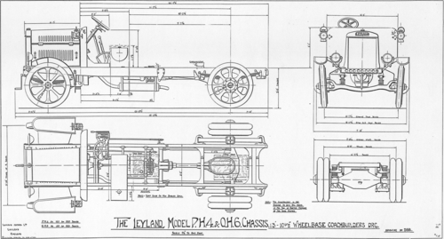
Figure 2.1Coachbuilders’ Drawing of the Leyland Model PH 4 Truck Chassis [1]
Light shines on the vehicle from the top-left corner, putting the outlines on the bottom-right corner in shadow. These are double-thickness lines and give the impression of shadow. Though this is essentially an overview drawing, note that there are no tolerances. The coachbuilders may have had their own drawings, but they would have relied on their own personal skill to produce accurate coach bodies.
Throughout the 20th century, design grew in importance as accuracy improved, both in manufacture and in drafting methods. The accuracy of information also improved, with more reliable analysis and the use of standards.
Genichi Taguchi, a Japanese manufacturing and statistical engineer whose most significant work was publicized in the 1950s and 1960s, expounded theories relating to the quality of manufactured goods. He was aware that the quality of manufactured goods was usually left to the manufacturing craftsmen to achieve. Taguchi suggested that quality could be designed in before components were manufactured. He also recognized that to achieve designed-in quality, the designers’ mindset had to be changed.
As designers were eventually made more aware of the “new” design method, manufactured goods became more available at lower cost and higher quality. Engineering designers created better components by introducing standards, tolerances, and precision machine tools, which led to large-quantity production methods. The design function had now passed from the lone artisan through to a complete design department, with methods and tools to assist very sophisticated design work.
Modern designers are equipped with tools that a few years ago were mere dreams. Tools such as 3-D CAD modeling software are able to reproduce lifelike images of complex components on screen, without having to building them as prototypes. This software is equipped with stress analysis, dynamics, and thermal analysis tools (and many more) that allow the designer to perform complex analytical calculations that often are impossible to perform by hand. Very sophisticated designs are now possible, and accurate modeling and drawing production permits manufacturing production to be much more automated. Indeed, once the image is digitized into computer memory, that data can be moved to other functions such as purchasing, manufacturing, or marketing and easily shared. This capability assists greatly in improving a product’s time to market. Designers no longer need to be in the same factory as production. A designer in the United Kingdom or the United States can create designs and e-mail them to a production facility in the Pacific Rim, say, China. The information can now be downloaded directly to computer numerical control (CNC) machine tools, where technical details are fed to the machine electronically and do not appear on paper drawings.
The results of CAD modeling and simulation software are so good that often prototypes do not have to be built. As designers move into a more and more sustainable role, this feature is of great benefit, since it reduces environmental impact. Furthermore, it is possible to print a 3-D image that gives a 3-D physical form. This image may be used to prove analysis, perhaps in a wind tunnel, or even used as an end component.
The possibility of printing a component is very exciting, since it uses a material-build process rather than a material-removal process, therefore giving zero waste. Another plus is that components can be created close to the assembly point rather than being manufactured overseas, thereby sparing a great deal of fossil fueled transport. The 3-D printing process has great potential of being a very sustainable feature of the constantly expanding design technologies.
The design function, whether for a lone designer or a full design department, is now in control of the design process and much of the manufacturing process. The designer creates value and disseminates information so that the product can be manufactured.
2.3 The Design Approach
Design is often performed by nontechnical people, and most of the time this is adequate. They will create something that works for them. Unfortunately, this approach may be expensive, since to make things feel safe people tend to overdesign, which costs money. Rule of thumb and perception of strength always tend to make things bigger than necessary. It is a human failing to overdesign in the belief that “it is better to be safe than sorry.”
Before the advent of detailed stress analysis techniques, engineers had only one recourse, and that was to build things so that they looked safe. They generally worked to the principle of “if it looks right, it is right.” Often buildings were built to very heavy specifications because materials were cheap but also because things were “built to last.” The United Kingdom has an enormous number of buildings that are hundreds of years old and that were essentially overdesigned.
Imagine building an aircraft to this regimen. The aircraft would probably be so heavy that it would never fly. The lesson here is to look at the outcome of the product. A multistory car park design may be optimized to give a perception of strength to the users, and indeed it may require some overdesign to achieve that goal. An aircraft, however, will need to be optimized for light weight. In general it can be considered that the lighter the aircraft, the greater the payload and the higher the efficiency. Land vehicle designers have also optimized their vehicles for reduced weight in order to increase fuel efficiency and increase payload.
Generally, designers need to optimize design toward cost, which is the one single parameter that drives almost all designs. A second major optimization parameter that should influence designs is that of sustainability. The common misconception is that sustainability is expensive to incorporate, but true sustainability reduces environmental impact and often gives reduced manufacturing and running costs.
Though designs can be optimized to achieve certain goals, the designer really needs to be led by the product requirements and tools, such as stress analysis, dynamic analysis, thermal analysis, and the like. Using these tools, designers can refine a design to give maximum performance for reduced cost and reduced weight and still have that design be sustainable.
The final concept design for a foot-pedal arrangement for a high-performance, lightweight vehicle is shown in Figure 2.2.
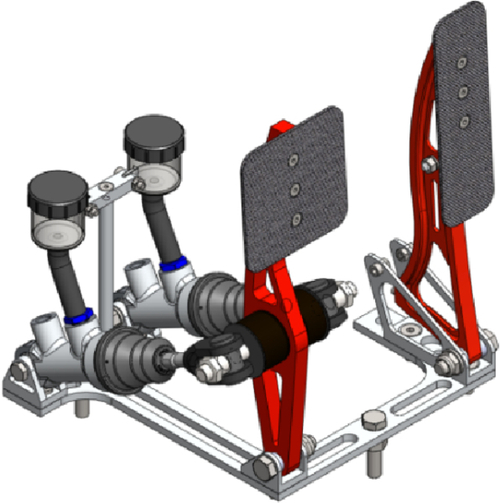
Figure 2.2Final Concept Design for a High-Performance Vehicle [3]
Various criteria were involved in the design of the pedal bracket, one of which was the necessity for reduced weight. Often a reduction in weight also means a reduction in strength. The design of the foot pedals optimized the reduction in weight and further optimized the high strength, even though these two parameters were in conflict.
Figures 2.3, 2.4, and 2.5 show how the step-by-step design process was influenced by stress analysis.
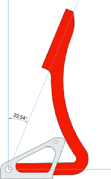
Figure 2.3Side View of the Accelerator Pedal; Initial Concept Design [3]
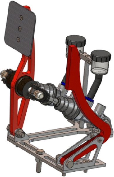
Figure 2.4Initial Concept Design of the Accelerator Pedal Shown In Situ in the Pedal Bracket [3]
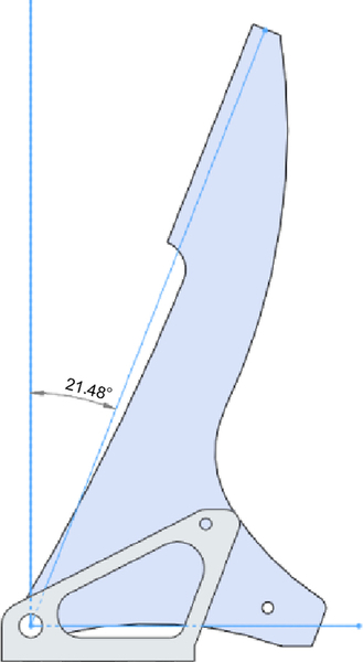
Figure 2.5Second Concept Design Without Weight Saving [3]
After cursory analysis it became clear that the initial concept did not possess the required strength. A plate version without weight saving was therefore developed (see Figure 2.6).
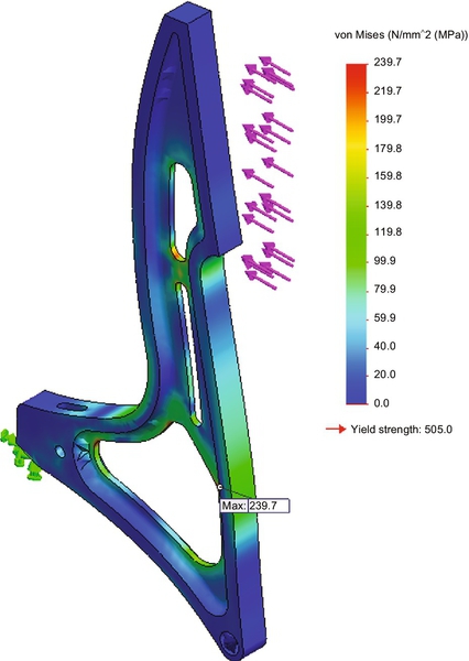
Figure 2.6Finite Element Stress Analysis Model of Concept 2 [3]
In Figure 2.6, material has been removed to reduce the mass of the pedal. Stress analysis was necessary to ensure that strength of the new shape was not compromised by the reduction in weight.
Optimization is a very necessary part of the design process, often juggling conflicting parameters. In our example, weight reduction was important, but just as important was the inherent strength of the pedal bracket. Using analysis tools it was possible to obtain an optimized design combining conflicting parameters of low weight and high strength.
2.4 Attributes of a Successful Design Engineer
To be a successful design engineer, it is necessary that the designer possesses knowledge and is disciplined across the whole range of engineering skills. Design is a process that brings together and combines a whole range of engineering processes and topics. Some of these are as follows:
• The engineering design process
• Analytical skills
• Management of design
• Communication methods and skills
• Communication devices (CAD)
• Manufacturing, including casting machining, forming, etc.
• Protection of intellectual property rights
• Cost analysis processes
• Sustainability in engineering design
• Design for production
• Knowledge of standards
• Diplomacy
This list is not exhaustive, but it outlines the vast knowledge and skills required by a successful engineering designer.
The successful design engineer is someone who understands the needs of his client. A client may only think he knows what he wants and will try to persuade the design engineer that the design should be achieved in a particular way. The designer must take a step back and ask himself what the real requirements are. He must see through what the client thinks he needs and employ his skills and experience to provide the client with an efficient solution.
The normal technique when confronted by a new design challenge would be to develop several potentially successful solutions. Depending on the design challenge, the solutions may not necessarily be developed simultaneously; indeed, one solution might appear to be very favorable but on receipt of further information may be rendered completely unusable.
For example, the designer of a flywheel kinetic energy storage system developed a flywheel rotor that rotated at 18,000 revs per minute. According to the information supplied by one particular manufacturer, the rolling element bearings that would support the load could only be used at a maximum speed of 6,600 revs per minute.
The solution to this problem was to suggest magnetic levitation bearings, which held all the advantages the design required to support the flywheel rotor. At this point two pieces of new information negated the use of magnetic levitation bearings:
1. During the investigation and sourcing of magnetic levitation bearings, it was found that they were far too expensive for the device to be manufactured economically.
2. Stress analysis on the rotor showed that the speed of 18,000 revs per minute would overstress the material and burst the rotor.
These two facts meant that the speed of the rotor had to be dramatically reduced to 4,000 revs/minute. At this speed, not only would the rotor stay intact, but the use of off-the-shelf hybrid rolling element bearings was now possible.
This example highlights the case where possible excellent solutions have to be ruled out on receipt of particular pertinent information.
2.4.1 A creative attitude
The designer must possess a creative attitude and have the self-confidence to search for a solution. This is demonstrated as follows:
• A willingness to proceed in the face of incomplete and often contradicting data and an incomplete understanding of the problem
• The recognition of the necessity for developing and using engineering judgment
• A questioning attitude toward every piece of information, specification, method, and result
• Recognition that experimentation is the ultimate method of finding correct information
• A willingness to assume final responsibility
With experience, the designer will develop the confidence to improve on or create solutions based on his or her skill, experience, and abilities. All designers will have at some stage created good designs and poor designs. It is the analysis of these previous designs that builds on experience and later leads to the confidence to create improved designs and new designs. The analysis of previous work often leads to improved designs and new design concepts.
2.4.2 Constructive discontent
Satisfaction with the status quo is often the enemy of discovery and creation. The designer needs to develop attitude and interest that deliberately looks at other designs, shortcomings in designs, and unfulfilled needs.
2.4.3 A positive outlook
The designer needs to nurture the belief that with cultivation, several different solutions can be developed. The designer will then be able to select and develop the best solutions. As the solutions are developed further, novel iterations may come to light.
2.4.4 An open mind
When first considering the brief for a particular design, the designer first needs to look at the requirements and constraints. With an open mind, many possible solutions across many technologies may present themselves. The designer then needs to use her experience and expertise to reduce these possibilities to practical options.
2.4.5 Design courage
The courage to create workable and efficient designs comes to the designer gradually. This courage comes from experience. At the beginning of a designer’s career, there is little experience, and some designs may fail or perhaps be inefficient. Learn to overcome the obstacles with persistence and the flexible approach. Courage and experience will grow at the same pace.
Design courage comes in many forms. One notable example was Barnes Wallis, the engineer and inventor of the bouncing bomb. He had courage that his device would work, even in the face of much ridicule. Another example of design courage is that of the NASA design team who, in the 1960s, had the courage to design and build the Saturn V moon rocket. The task was huge, the rocket was huge, and no one had accomplished this trip before. The design could not be allowed to fail, since lives and national pride were at stake. A glimpse of the enormity of the design can be seen in Plate 2.1, which shows the huge size of the five rocket nozzles that lifted the spacecraft off the launch pad.
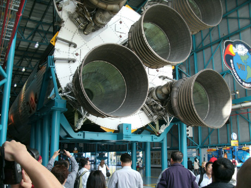
Plate 2.1The Five Rocket Nozzles of the Main Stage, Saturn V Rocket [1]
2.5 The Classic Design Approach
Engineering design lies at the heart of engineering. It is the one discipline that combines all others, including stress analysis, thermal analysis, dynamic analysis, manufacturing, and materials processing.
Design is the process that starts as a visualization in the designer’s mind. The designer teases out the specification, applying engineering principles and finally technically communicating his brainchild so that the object or product can be manufactured.
Engineering design is not an exact science but rather an art that uses scientific principles and concepts as its framework. It is at the design stage that the work of many specialists is brought together, and it is the function of the designer to find solutions to design challenges using scientific principles to define design parameters.
The discipline of design is a rational process of decision making, considering each challenge as it arises and searching for solutions. The designer should attempt to create several differing solutions utilizing different methods or components. The next step of the decision-making process should be to select a particular concept for further development or perhaps combine several concepts into one final specification.
Though scientific principle is the cornerstone of good design practice, design challenges may be arrived at by several different approaches:
• Calculation and analysis
• Experience of similar problems
• Intuition
• Application of the results of research
The standard approach to design can be expanded further and can be seen in the Classic Design Approach flowchart in Figure 2.7. As the chart shows, that design journey has three major phases:
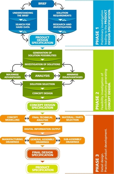
Figure 2.7Classic Design Flowchart [1]
1. Preliminary investigation, leading to the product design specification
2. Investigation of possible solutions, generating the concept design specification
3. Detail design, leading to a final design specification
Each of the three design phases finds its completion in a particular specification. The specification element is an important way-marker on the design journey, since it should be compared against the needs of the product. If a specification does not match the needs of the product as set out in the brief, the design process has to be returned to the previous stage.
2.6 Design Specifications
Throughout the design process, specifications are developed and modified as new information and new designs unfold. This re-evaluation is necessary to keep the design on track and to ensure that the original requirements are met. New specifications are really checkpoints along the design journey.
There are normally four levels of specifications derived from the classic design approach shown in Figure 2.7 during the design of a product. These levels are:
1. Product design specification (target specification)
2. Concept design specification
3. Final design specification
4. Product specification
These four specifications represent stage completion on the route to the product’s final design. Each specification lists a set of parameters that are either things that the product should be able to do or things that the product can do. In the early stages of a design, the specification outlines parameters that the yet undesigned product should be able to achieve. In the later stages of a design, the specification should define the parameters that the product can achieve.
The designer should be clear on the content and purpose of each of the specifications, since they can be used as a measure of progress throughout the design process.
The product design specification (PDS) is a target specification and a statement of what a not-yet-designed product is intended to do. The aim of the PDS is to ensure that the subsequent design and development of a product meet users’ needs.
The concept design specification (CDS) takes place after a feasibility design and a conceptual design have been formulated. This specification predicts what the concept should be able to achieve and is a checklist against the original need for the product.
The final design specification (FDS) must include all necessary technical specifications and should be a complete set of instructions on how to build, operate, and maintain the product.
The product specification (PS) is the final specification that should be attached or enclosed with the product. This is formulated after the product has been built and tested and lists specifically what the product can achieve and what the product requires for it to work efficiently.
2.6.1 Product design specification (target specification) (PDS)
The brief makes the first request for a design solution. As the designer teases, investigates, and understands the brief, a target specification or PDS is created. This is a statement, or at least a list of requirements and constraints, of the performance of the new product. Its aim is to ensure that the design and development of the new product meet users’ needs.
The PDS is formulated as a consequence of interrogating the brief. The brief may set out what is required, but it is not until the designer fully understands the brief that the PDS can be formulated. The PDS will carry requirements or needs as well as constraints. In the design for a 50-meter-wide car park, for example, the designer may have a requirement to park 25 cars side by side. The constraint would be that each parking place can be a minimum of 2 m.
The proposed specification combines the information that is currently known and suggests a wish list of requirements and constraints in the final design solution. For example, consider planning a trip from Edinburgh to London passing through Carlisle, Liverpool, and Birmingham. As the journey is undertaken, information may come to light that causes us to change direction. For instance, road works in Liverpool have changed the route to go through Leeds instead.
The same is true of an engineering design. A conveyor system that is powered by electric drive motors works well in a dry atmosphere, but when the conveyor is placed in a very wet environment, the electric motors would fail. Hydraulic motors would be an excellent replacement because they would not be affected by the wet environment. Here new information came to light related to the working environment, and that information changed the direction of the design.
2.6.2 Functional parameters and metrics
We previously explained that the PDS contains requirements and constraints. Many of these elements, such as volume, force, velocity, and mass, will be measurable values. The brief will set out requirements and sometimes will give values, but very often the designer has to develop the design to a stage where he can predict the design parameters as a set of numeric values.
Metrics are a measurement element which defines in precise terms the physical attributes of the new product, how the new product should perform and what it should use as consumables to achieve those physical attributes and that performance. These metrics should form a substantial part of the product design specification and match the requirements originally set out in the brief, even if the brief does not specifically state.
2.6.2.1 Example: kinetic energy storage device project (flywheel)
A very wide brief was given to create a flywheel system that would store mechanical kinetic energy in a rotating mass. The intention was to store electrical energy as kinetic energy, then feed it back into the national grid to smooth out high demand for electricity. When the designer requested the physical parameters such as diameter, mass, and speed, the only parameter given to the designer was that it should store 20 KWh of kinetic energy. This parameter was the only metric given in the brief, and it was derived from the requirements for selling the energy back into the national grid. The only other major requirement built into the brief was that the flywheel should be built to comply with sustainable engineering values.
The designer was faced with a very broad field of possibilities that needed to be simplified. Some of the main questions were these:
• Large heavy flywheel?
• Several small flywheels?
• Speed: high or low?
Many flywheels in operation made use of high speed, given the kinetic energy equation:

where
I = Moment of inertia (Kgm2)
ω = Angular velocity (rad/sec)
It can be seen that if the angular velocity ω is increased, the kinetic energy is squared. Many designers and researchers used an increase in speed to create a greater kinetic energy capacity. Stresses within the rotor suggested that the angular velocity should be reduced substantially.
The reduction in speed brought enormous benefits to the cost and the sustainable manufacture of the flywheel system. It enabled use of standard bearings, normal machining practices, easily obtainable materials, shorter development time, and low-cost manufacture with a high sustainability factor.
The product design specification was formulated and included the following metrics:
• Kinetic energy storage: 20.1 kwh
• Power available: 5.6 kW
• Angular velocity: 4,000 rpm
• Angular velocity: 419 rad/second
• Diameter: 2 m
• Mass: 1,650 kg
• Bearings: Standard hybrid ball bearings
To formulate the product design specification and meet the targets of 20 kwh kinetic energy storage, a good deal of analysis was conducted to create an accurate target specification. Many of these parameters were taken through to the concept design specification after verification through the selection of a solutions process, which followed in Stage 2.
The PDS would therefore contain essential metrics to assist in Stage 2 Concept Design, where design solutions need to be formulated.
2.6.3 Concept design specification (CDS)
The concept design specification is formulated after much work has been done in researching the possibilities for a solution to the design challenge. As the PDS is investigated, several solutions will emerge. It is suggested that between three and five solutions be formulated, all of which will fulfill the design challenge to varying degrees of efficiency. It is necessary for the designer to evaluate each solution against various constraints such as cost, size, power, environmental impact, and so on.
The outcome will be a concept solution that can also be termed a feasibility solution. From this solution, the designer will be able to propose a specification describing the performance of the conceptual product. This is the second specification in the design route and should be checked carefully against the original needs of the design challenge.
2.6.4 Final design specification (FDS)
An FDS must include all necessary drawings, dimensions, environmental factors, ergonomic factors, aesthetic factors, costs, requirements, quality, safety documentation, and disposal methods. This specification is the culmination of all the design work that has led to the concept and the detailed design work that has converted the concept into a practical design. The FDS should be a complete set of instructions on how to build and use the product.
For simple products such as an electric alarm clock, the FDS may be a one-page document that outlines power consumption and instructions for use. In the case of a ship, for example, the document may run into many thousands of pages outlining the working requirements, maintenance requirements, and all necessary information relating to the millions of components that contribute to the efficient working of the ship.
2.6.5 The product specification (PS)
The product specification should be attached to or enclosed with the product. It is the specification the customer will see and is normally derived from the FDS. The product specification is formulated after the product has been built and tested; it lists specifically what the product can achieve and what the product requires for it to work efficiently.
The product specification may be so simple that it is a straightforward copy of the FDS. The complexity of the product, such as a ship, may mean that the FDS becomes the product specification in its entirety.
2.7 Design Phases
Regardless of the type of product, the design process will follow a broadly similar path involving back-and-forth iteration. There are generally three phases to any design challenge. Phase 1 is primarily an investigation phase that interrogates the brief and looks at similar methods and processes; the culmination of this phase is to create a PDS.
Once the brief is understood and information is gleaned through initial research, the creative design process can commence. This phase involves the creation of several solutions to the design challenge and an analysis of feasibility for each of the solutions. The outcome of the second phase is to create a concept design and a concept design specification.
The third phase converts the concept design into a practical product by selecting materials, components, manufacturing methods, and the like. This phase culminates in a final design specification that describes what the product will achieve and what the product requires in order to function.
Each of the design phases can be subdivided into a progression of activities as follows:
Phase 1: Preliminary Investigation Leading to the Product Design Specification
• The brief
• Exploring the brief
• Defining solution requirements and constraints
• Product design specification
Phase 2: Investigation of Possible Solutions and Generation of Concept Design
• Generation of solution possibilities
• Analyzing several solutions for feasibility
• Selecting an appropriate solution (concept)
• Concept design specification
Phase 3: Detail Design and Conversion of the Concept into a Practical Product
• Detail development: modeling, selection of parts
• Manufacturing data, drawings, models, instructions
• Final design specification
• Product specification
2.8 Phase 1
2.8.1 Preliminary investigation of the design challenge
The preliminary investigation of the brief is arguably the most important part of the design challenge. If the brief is not investigated properly and thoroughly, the solution to the design challenge may be completely inappropriate. It is important that the brief is interrogated thoroughly so that the designer knows exactly what is required and what constraints should be included.
This investigation extends beyond the brief in that other research should be conducted. This research could be in the form of competition or perhaps patent searches. This research is necessary to build a complete picture of the design challenge and formulate the PDS.
2.8.2 The Brief
The creation of the design will naturally start with some form of brief. This brief could be of the following types:
• Written. Written briefs are usually much more formal than others and have a commercial content. They should include a list of requirements and constraints. Such a brief may well be accompanied by a formal contract.
• Verbal. Verbal briefs tend to be less formal, and since they might not have requirements attached, they may well be less accurate. This kind of brief should be reviewed carefully since verbal misunderstandings may well result in arguments between principals, which will then lead to lost time and perhaps loss of money.
• Perceived (“I have a good idea”). Perceived briefs are very informal and are often the result of conversations between friends or perhaps individuals who have “good ideas.”
2.8.3 Exploration of the brief
The brief is the very first information relating to requirements of the new product. It possesses the key information that will specify the design requirements. The designer must understand the brief completely if the design is to comply with the requirements set out in the brief. He or she must analyze what is required, perceive the final product, and provide a target specification, sometimes called a product design specification (PDS). To do this the designer must “climb inside the brief” and understand every nuance.
An inexperienced designer may look at the design challenge and think it is simple, but an experienced designer will look at the same design challenge and remember the adage, “If you think the challenge is simple, you don’t understand the challenge.”
If the designer is asked to design a chair, she must understand the material of manufacture, the manufacturing process, and what the chair has to go through when it is in use. He/she must understand that the joints will creak and move, the seat will sag, and the structure will groan.
To take an artist’s is point of view (see Figure 2.8):

Figure 2.8Understanding the Feelings of a Chair [1]
“Climb inside” the chair
Understand the stresses being applied to its crossbars and legs
Feel the stresses that the chair feels
Live the feelings of the chair
Understand its creaks and groans as it is sat upon
Become the chair!
By understanding the brief in this way, the designer can better understand the design challenge and fully apply design experience to develop a full solution.
The process of understanding the brief is really to ask the correct questions. In a class session the author suggested to the class that he needed to get a car between two towns about 30 miles apart. He invited the class to ask appropriate questions to better understand the challenge.
Some of the questions were as follows:
Does the car have an engine? Answer: No
Is the car able to be steered? Answer: No
Is the car in pieces? Answer: No
Can it be pushed? Answer: Yes
Does it matter if it rains? Answer: No
Can it be carried on a trailer? Answer: Yes
Many of these questions assumed that the car was a full-size vehicle. It was only when one student asked “How big is the car?” that the true answer was given. The car was a children’s toy, and it was carried to the next town in a carrier bag on public transport.
In his quest to understand the brief, the designer should create a wish list of requirements the design should fulfill. Equally, there may be some constraints that may be the same as the requirements. For example, a requirement for a vehicle might be that it should carry four passengers. Conversely, a similar constraint may be that it should carry no more than four passengers. Armed with the list of requirements and constraints, the designer may then proceed to the research phase.
Though constraints and requirements may be similar, the general approach is that constraints will create an envelope in which the design may be accomplished. Requirements are really “need to know” items and describe the performance of the design. Sometimes requirements and constraints cannot be given in the brief, but they may become evident as a result of research.
2.8.4 Exploration and research outside the brief
To understand the whole design challenge, it is necessary for the designer to immerse himself in the extent of the challenge and all its nuances. If the designer is new to the industry, research may involve understanding working practices and methods within that industry. Should the designer be a specialist within the industry, he may well already be aware of industry practice. Nevertheless, to gain a full understanding of the design challenge, research is always necessary. Depending on the product, research could involve many different areas, from competition research through high-level scientific research.
2.8.4.1 Competition research
Probably the first step in any research would be to “see what is out there” in terms of the competition. This may be very enlightening since the competition’s products will already be serving the market and will have already been designed and manufactured. Analyzing the competitors’ products will give insight into new techniques, materials, and manufacturing processes and perhaps give insight into improvements.
2.8.4.2 Patents research
Most new product development will require some form of patents search. This search will inform the designer if the design he is proposing has previously been considered. If a product is designed, manufactured, and marketed and closely resembles a patented product, a heavy lawsuit could be applied by the original patent owner. A patents search will also reveal technical details of closely related products. Furthermore, the “claims” within a patent will inform the designer of the exact capabilities of the device. This finding may or may not allow the designer to “break” the patent. Breaking patents by avoiding the patented claims is completely legal, as opposed to illegal patent breaking, where the product is directly copied and marketed. Example: One of the claims for a charcoal ignition system may be that it should be used a s a free standing device. This means that to break this part of the patent it could be incorporated in to a larger device and therefore used in a different way. There may, however be other claims which preclude this. The patent breaker needs to take care not to infringe other claims.
2.8.4.3 Scientific research
Scientific research can be expensive. Much of the development of highly technical components and products such as aircraft, vehicles, silicon chips, solar panels, new materials, and so on has been achieved through enormous injections of money into specific research.
The BAE Systems A380 Airbus, shown in Plate 2.2, has a maximum take-off weight of 650 tonnes. To achieve this mass, a great deal of design effort was injected into the project. This effort included not only the design of aircraft components but also the research and development of new techniques and materials. To reduce the mass yet keep the strength, the fuselage required the development of a large, very specific composite structure and was the result of some high-level research. The total cost of development of the A380 Airbus was estimated at $18 billion.

Plate 2.2Airbus A380 [2]
2.8.4.4 Component research
Many specialist manufacturers make standard components that can be fitted and combined directly in a design. These components may include bearings, seals, screws and fasteners, electric motors, gearboxes, engines, and many, many more off-the-shelf items.
The manufacturers of a stone tumbler (see Plate 2.3) would normally manufacture the special components such as the drum and the chassis. Off-the-shelf standard components were such elements as wheels, bearings, and drive unit. These parts, shown in Plates 2.3, 2.4, and 2.5, would be purchased from component suppliers.
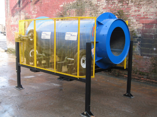
Plate 2.3Stone Tumbler [1]

Plate 2.4Tumbler Bought-Out Parts, Comprising Plumber Block Bearing and Vehicle Wheel [1]
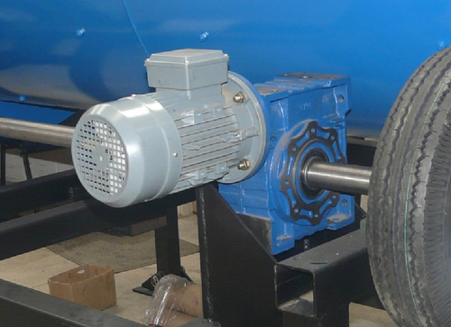
Plate 2.5Tumbler Bought-Out Part: Drive and Reduction Unit [1]
2.8.5 Cost and sustainability
During preliminary investigation, the cost and sustainability of the product are not a large element of consideration. However, cost is always a limiting factor and can be considered a major constraint. It does not matter how well a product might function; if it is too expensive, it will not sell. Cost, and more recently, sustainability, has therefore to be major considerations in the back of the designer’s mind at all levels of the design process.
A high-level industrialist recently observed, “Everything costs money.” This doctrine should now be expanded to include sustainability: “Everything costs money and everything has an environmental impact.”
This adage should be adopted by every designer and should be considered at every stage during the design process. As the design progresses, cost and sustainability will grow in importance since they will steer the design toward a low-cost and sustainable product.
2.8.6 Factors to consider for the product design specification
The variety of designs in engineering precludes creating a rigid list of parameters that can be applied to developing a design or specification. However, many factors could be considered and are useful as a checklist, as discussed in the following sections.
2.8.6.1 Duty factors
1. Required form of action (what are the working principles?)
2. Mechanical loading (type and magnitude-static/dynamic/shock/constant/variable/cyclic)
3. Speeds (given/determined by the chosen design configuration; constant/variable)
4. Cycle time (strokes per minute or hour/hours per week)
5. Power sources available
6. Required life (total life/life between servicing in years/number of cycles, etc.)
7. Degree of reliability required (operating life without attention, likelihood of premature failure)
2.8.6.2 Environmental factors
1. Temperature extremes (effect on material properties; problems caused by differential expansion)
2. Humidity (problems of corrosion or of drying out)
3. Chemical or dirt contamination (from surrounding sources or contaminating the surroundings
4. Vibration and noise, shock loading
5. Tampering (could the operator or passerby interfere with the machine?)
6. Maintenance (will it be easy or impossible? will it be conscientiously applied?)
2.8.6.3 Sustainability factors (environmental impact)
1. Where will the raw materials be sourced? (transport impact)
2. Will manufacture have a low environmental impact (smart factories’ use of high-tech models to reduce build impact)
3. Environmental impact in use (has use been made of low-impact materials and usage methods, e.g., the use of a lean burn diesel engine in an item of plant)
4. Designed for long life (larger bearings ability to maintain components, refurbishment)
5. Design for disposal (4R approach: reuse, recycle, reduce, refurbish)
2.8.6.4 Economic and manufacturing considerations
1. The position in the “cost-quality” spectrum (standard of accuracy required?)
2. Quantities required, delivery rate and date
3. Capital cost
4. Operating cost (energy cost/efficiency; cost of replacing failed or worn parts)
5. Material availability (scrap utilization)
6. Manufacturing facilities available (small firm or large firm? is the manufacturing equipment fully committed on other work?)
7. Use of existing and bought-out components
8. Interchangeability (can it be done? components, subassemblies, whole units)
9. Adaptability (suitable for wider uses? any advantages?)
2.8.6.5 General factors
1. Size (any limitations? often uncertain dimensions; compactness is often a good selling feature)
2. Weight (is it important?)
3. Rigidity/flexibility (not the same as strength)
4. Appearance (another selling feature; create a product with good function and good aesthetic form)
5. Ergonomics (put operating controls in convenient positions; operator seated? foot control?)
6. Safety (guards, etc., for operator safety; overload devices to protect machine.)
7. Safety factors (possible failure modes; consequences of failure; is it fail-safe? reliability of materials and manufacture, accuracy of calculations)
8. Ease of handling and transportation
9. Standards (British Standards, International Organization for Standardization [BSI/ISO], American National Standards Institute [ANSI])
The relative importance of these various factors depends on the application of priorities that must be established by clearly visualizing the design challenge. Not all the factors will be usable in any single design challenge, but the list is an excellent memory jogger when PDS's are formulated. Furthermore, the list is an excellent guide when developing several different solutions.
2.8.7 Metrics
Part of the PDS must include measurable elements of the design. These elements, termed metrics, are indicators of performance or consumption. Metrics for a passenger vehicle might include a mass of 750 kg and a fuel consumption of 75 mpg. These can often be taken from the list of requirements and constraints, but sometimes the brief is extremely vague and it is not until feasibility calculations have been performed that some of these metrics can be formulated. However, they should be included in the product design specification, since these measurable elements will allow the designer to target the design formulation more precisely.
2.8.8 Preliminary investigation overview
During the investigation and research process, a greater understanding of the requirements and constraints will be gained. The investigation and search for hard data, which is then compared against the requirements of the brief, lead to the PDS (target specification). This is really the first list of performance comparators gleaned from the brief and will be used in future design development as a check to ensure that the design is heading in the correct direction.
2.9 Phase 2
2.9.1 Generation of solution possibilities
The completion of the PDS generally marks the end of Phase 1. It should be noted that the quest for new information and ongoing research will not cease throughout the life of the project.
More important, the PDS marks the end of Phase 1 and the start of Phase 2. At this point the designer or design team should be completely knowledgeable as to the requirements of the brief. Furthermore, the PDS provides a design target structure that will guide the designer.
2.9.2 Strategic thinking
The beginning of Phase 2 instigates the process for the generation of solutions to the design challenge. At this point it is easy to fall into the “inventor syndrome” by inventing a single solution and pursuing that solution at the cost of exploring other avenues. This path must be avoided by all means. Premature commitments can be dangerous since the designer might become attached to a bad concept, or at best the outcome will be an inefficient design.
It is normal practice to adopt a strategy of least commitment. Only after all other avenues have been evaluated and exhausted does the designer commit to the best of the solutions. It is good to remember the adage, “Never marry your first design.”
Another important strategy in design thinking is that of decomposition. This is a strategy of breaking down a much larger product into smaller subchallenges. A complex item such as a passenger vehicle cannot possibly be designed as a whole unit. The design is broken down into a smaller set of design challenges—for instance:
• Engine
• Body
• Suspension
• Braking
• Seating
• Chassis
• Wheels
• Tires
This list contains just a few of the major subcomponents of a vehicle. These may be split down even further—for instance, the engine may be split into the crankshaft, pistons, engine carcass, alternator, camshafts, and so on. When large components are reduced to individual systems and components, the whole design process can be made easier. This technique also allows specialists to work on their particular component or system.
A complex item such as a passenger vehicle will be split down into hundreds of smaller challenges, all of which, when finished, will come together as the complete passenger vehicle.
2.9.3 Solution generation
It is recommended that between three and five or more solutions are generated for each design challenge or subchallenge. Information thus created should be shared with other members of the design team in the form of sketches, models, and any other means that will allow efficient explanation of the various solutions. The explanations should be full and complete so that there is no ambiguity. The solutions should be accompanied by a list of valid and well-reasoned advantages and disadvantages that may need further investigation.
2.9.4 The tools of creativity
Generating new solutions is a creative process that relies heavily on the designer’s personal experiences. Designers will often suffer “mental blocks” relating to a design challenge, but there are tools available to help unlock the logjam. Solution generation is treated in a later chapter; for now, some of the major solution generation tools are described in the following subsections.
2.9.4.1 Heuristic redefinition
Heuristic redefinition is valuable for the individual designer who is working alone, unsupported by a creative team. It is a method of looking at a whole system in which a problem exists. Each major part of the system is itemized and visualized as to its contribution. At each stage the question is asked, “How can we ensure that … ?” Answering this question allows a redefinition of each of the elements and a possible solution to the original challenge.
2.9.4.2 Classic brainstorming
Classic brainstorming is a very popular method of generating solutions by a team. The tool allows team members to pool their knowledge creatively and in an open and uncritical environment. There is only one rule, and that is not to be critical of others’ ideas. Sharing a seemingly outlandish and obviously unworkable idea may well set another member of the team on a path toward a practical solution.
2.9.4.3 Imaginary brainstorming
Imaginary brainstorming is a variation on classic brainstorming except that it uses a “trick” that tends to shift people’s thinking “outside the box.” An example is to start with the question, “How can we improve communication between departments?” The trick here is to change the word departments to planets. This shift in thinking is quite effective in generating new solutions.
2.9.4.4 Word-picture associations and analogies
Associations and analogies are often used to generate alternative solutions. Associations are really mental connections triggered by an idea or a memory, picture, or event. For example, a piece of apple pie might stimulate memory of your grandmother’s home.
An analogy, on the other hand, is usually a more direct comparison of principle, action, or behavior. When R. J. Mitchell, the designer of the Spitfire, first designed the Schneider Trophy aircraft, he used the analogy of birds in flight to assist the design of the aircraft wings.
Analogies and associations can be generated through random words, pictures, biotechniques, and any other memory-provoking stimulant.
2.9.4.5 TILMAG
TILMAG is an acronym for transformation idealer lösungselemente durch matrizen der assoziations und gemeinsamkeitenbildung, which, loosely translated, means “the transformation of ideal solution elements in an association matrix.” This technique was developed by Dr. Helmut Schlicksupp. The basic principle is that a matrix of ideal solutions is created and cross-matched to deliver alternative solutions. This method is discussed in depth in a later chapter. It is particularly ideal for generating solutions to stubborn design challenges.
2.9.4.6 The morphological box
The morphological box is a structured method for systematically looking at key characteristics or parameters of a solution and the realistic options for each parameter. It helps the team to identify practical solutions to a problem by first defining the essential characteristics of possible solutions. For each parameter multiple options are defined thus when combined within a matrix a multitude of unique solutions are yielded.
2.9.4.7 Graphical synthesis
Graphical synthesis is a well-tried method whereby a single designer may generate his own solutions by using a large sheet of paper and developing sketched ideas. A large sheet of paper, probably A1 in size, is spread on a flat surface. The designer would have a list of requirements and constraints at hand and sketch a solution in the top-left corner. The development of this sketch could be horizontal across the top of the paper. Another development could be vertically down the left side of the paper. Solutions may develop from combinations of the horizontal and vertical sketches until eventually the whole sheet is full of combinations and progressions of ideas. As solutions develop toward the bottom-right corner of the paper, a unique solution should emerge. The general approach is illustrated in Figure 2.9.
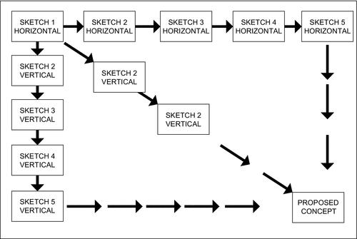
Figure 2.9Graphical Synthesis and Development of Possible Solutions by Sketching on a Large Sheet of Paper [1]
2.9.4.8 Synectics
Synectics is a formalized creative design method that uses analogical thinking as a main process. Various forms of analogy may be used as described here:
• Direct analogies. Using a biological example such as in the development of Velcro when the hooks on cockleburs were used as the analogy.
• Personal analogies. Here team members imagine what it would be like to use oneself as part of the system.
• Symbolic analogies. Poetic metaphors and similes are used to relate elements of one thing to aspects of another, such as the head and claw of a hammer.
• Fantasy analogies. These are impossible wishes for things to be achieved in some magical way. For instance, one may wish to lift a 20,000-tonne ship out of the water using a force beam.
We’ve identified some of the more popular methods of solution generation that are usually used when there is a tough challenge to solve. Experienced designers may be able to generate ideas without recourse to more formal techniques.
2.9.5 Solution evaluation and selection
Thus far the design process has been dominated by research and creativity, but solution evaluation involves the convergence of the design process toward a single concept. Solution evaluation is often an iterative process whereby solutions are explored and perhaps found to be lacking in some technicality. The process returns then to basic principles to modify or scrap the particular solution.
It is usual that between three and five solutions are developed. This creates a choice of different solutions for the designers to evaluate for their efficiency and effectiveness.
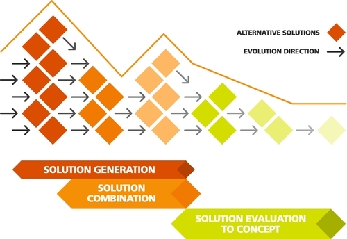
Evaluation involves a large set of possible solutions being reduced to a smaller set, but through the process of iteration these solutions may be subsequently combined and improved to increase the number of solutions available for selection. Figure 2.10 illustrates the successive narrowing and temporary widening of a set of options under consideration during the evaluation process.
No matter what the product or system or whether the selection process is prescribed or very free, designers and design teams will use methods to evaluate and reduce the concepts to a single workable solution.
Methods vary in their effectiveness and efficiency and include the following:
• External decisions. Various solutions are related to the client or another external body for their selection.
• Product champion. Often in a team design situation there is a dominant person. The chief designer may be a responsible member of the team who personally makes the final selection. Or there is a member of the team who is very opinionated and tends to speak the loudest. The decision may be based on his opinions. If a product champion is appointed, he may lead the team and may make the final decision.
• Intuition. The solution is selected by its “feel.” Explicit criteria or trade-offs are not used. The concept just “seems” better. This is rather a dangerous selection process since it is very subjective and could be based on whims and moods.
• Voting. Each member of the team votes for several solutions. The solution with the greatest number of votes is selected.
• Advantages and disadvantages. In evaluating design solutions it is normal practice to consider advantages and disadvantages of a particular solution. Simple evaluations can be accomplished in an informal manner, but it is always good practice to write down the positive and negative aspects of a particular solution.
• Prototype and test. A solution selection is made based on test data. This choice may prove to be an expensive approach since the item needs to be manufactured before the selection decision is made.
• Decision matrices (morphological analysis). This is a more formal selection procedure because each solution is rated against prespecified selection criteria. These may be weighted. Care should be taken in using this method, since subjective views may creep into the decision process. This method is discussed in detail later in this chapter.
Many experienced designers intuitively evaluate the solution options, which may be satisfactory for small projects with fairly simple selection criteria. Large and complex projects require a more formal evaluation procedure, which in some cases may need to be documented. The procedure may also need to be shared by the design team, which also may necessitate a more formal evaluation style.
2.9.5.1 Case study: removal of plywood from floor panels [10]
A project was given to a group of design students to design a small machine that would separate plywood facing from galvanized steel-covered floor panels. The floor panels can be seen in Plate 2.6. The plywood facing was adhered to the galvanized sheet steel floor panel by an epoxy resin. Research showed that this could not easily be separated by chemical means or high temperature and a more mechanical means would be required. After producing a PDS, the students proposed several methods to remove the plywood. Their list of methods with advantages and disadvantages appears in Table 2.1.
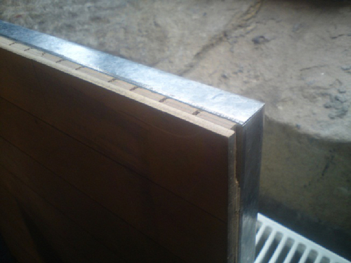
Table 2.1
Methods, Advantages, and Disadvantages for the Plywood Removal Case Study
| Method | Advantages | Disadvantages |
| Electric bandsaw | Possibility of keeping both steel and wood as reusable components Cheap to purchase Able to run from 240v source | High maintenance costs (epoxy resin will cause high wear on saw blades) High temperature may warp the ply, therefore negating the advantage of keeping it intact Slow separation process Sawdust |
| Industrial plane | Quick separation Easily automatable process High initial cost | Expensive High maintenance (lots of moving parts) Dust/debris No chance of saving wood |
| Cutting wire | Low initial cost Intact plywood Low maintenance cost | Possibly not effective Slow Inaccurate |
| Hydraulic machine blade | Safety (stationary blade) Design simplicity Relatively cheap Low wear and therefore low maintenance costs Quick process | Fairly high setup costs |
Even though the parameters for each solution are reasonably simple, it is not easy to intuitively evaluate the best method. A more formal process could be used in maximizing advantages and minimizing disadvantages. Several methods are available, but perhaps the most popular is the morphological evaluation chart shown in Figure 2.11.
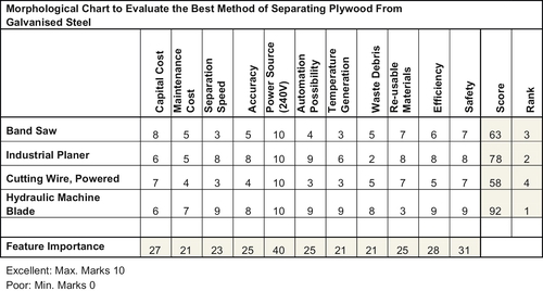
Figure 2.11Morphological Evaluation Chart [1]
The morphological chart allows the designer to evaluate each of the parameters the different solutions might give. If each parameter is given a value, in this case, a maximum of 10 marks, a total at the end will show the score and hence the rank. In the preceding case it was the hydraulic machine blade that was deemed to be the best design option.
There must be a note of caution here, since allocating marks is a very subjective activity and can be subconsciously weighted by the designer. Furthermore, the designer may have a particular vision in mind, which will also subconsciously throw the mark allocation.
The morphological evaluation chart is a very powerful tool when used properly and its shortcomings are understood. It is able to sift the various parameters within several solutions and put them in order.
The features or parameters can be arranged so that the most important are on the left of the chart and ranked so that the least important will be toward the right of the chart. In this way the chart can be manipulated. Instead of 11 columns, the first five most important features can be evaluated.
2.9.6 Use of the morphological chart
It is important to use the chart properly in order to overcome the subjective nature of marks application. Should the list of solutions be much longer than just the mere four we’ve mentioned, it would be normal to choose the top three ranked solutions for further evaluation.
Should the designer choose the top-ranked solution and say, “This is it!”? There is a danger that even though ranked number one, a solution might not possess some qualities that are absolutely essential for the design challenge. It is therefore important that more stringent evaluation takes place over perhaps the top ranked three solutions. This can be done by the designer manually checking the outcome of the top-ranked solutions against the PDS.
Considering the morphological chart in Figure 2.9, the number-one ranked solution is the hydraulic machine blade; number-two ranked is the industrial planer. Both solutions will fulfill the PDS. The main difference is that the industrial planer will create a great deal of small friable debris, which can be bagged, is easily shipped, and is ideal for recycling into chipboard. On the other hand, the hydraulic machine blade produces broken, flat, large pieces of plywood that cannot easily be recycled and for which the only disposal solution may be by burning.
According to the morphological chart in Figure 2.9, the top-ranked solution is the hydraulic machine blade, yet in selecting this tool, the designer is creating a problem of the disposal of the broken pieces of plywood. Should the designer instead choose the number-two-ranked solution, the industrial planer, the problem of disposing of the debris is already solved.
In considering the design in a whole-life sense, it is more appropriate to adopt the number-two-ranked solution than the number-one-ranked solution. The planer will adequately fulfill the needs of the PDS, and it gives the added benefit of sustainable disposal of the debris.
2.9.7 Benefits of a structured selection and evaluation method
The response of the marketplace to a product critically depends on the selected solution, but the solution selection can also dramatically influence the manufacture and cost of the product as well as the environmental impact.
For example, the solution for the flywheel system mentioned earlier was to create a flywheel with a fairly low speed, which allowed the materials procurement and manufacture process to be kept to that of normal practice, thus reducing the environmental impact and improving the value of sustainability.
The alternative option would be for a high-speed flywheel that would require magnetic levitation bearings, composite flywheel, vacuum chamber, and a long lead time to market. There were many other elements of a special nature were required, making this option very expensive and much more unsustainable than the low-speed option.
A structured solution selection process helps maintain objectivity throughout the selection process and guides the production development team through a critical, difficult, and sometimes emotional process. A structured solution selection method offers the following potential benefits:
• Products that meet the PDS. Concepts are explicitly evaluated against customer-oriented needs.
• Better manufacturing. Precise evaluation with respective manufacturing criteria improves the products’ ease of manufacture and helps match the product to processes.
• Competitive design. The design team will attempt to match or exceed key metrics compared to competition.
• Reduced time to market. A structured method tends to coordinate all players within the design team to all those outside the design team, such as manufacturing engineers, industrial designers, marketers, and project managers. This results in increased certainty and better communication.
• Documented decision process. A structured selection method results in an archive and rationale behind selection decisions. The record is useful for introducing new team members or for quickly assessing changes in customer needs. Historically it may be used as a start for a new but similar project.
2.9.8 Concept design
The concept design is an important way-marker for the whole design process. It marks the culmination of a great deal of investigative work and solution generation coupled with practical engineering knowledge as to the best method of achieving an appropriate outcome to the design challenge.
The concept design illustrates the best option to meet the design challenge with the available technology, funding, and skills. It is an opportunity to check the function and performance of the design against the requirements of the design challenge. The concept design specification should therefore be checked against the PDS, and of course they should match completely. In the real world, a 100% match may not be possible, but those elements of the specifications that do not match should not be detrimental to the functioning of the proposed product. Should the mismatch be unacceptable, a return to solution generation is advised.
The concept design is also important to show prospective clients the attributes of the new product. This can be shown in many ways. The presentation can be prepared as a poster, a verbal presentation with slides, a set of 3D models (see Plate 2.7), a physical model such as that which an architect might present (as shown in Plate 2.8), and many other communication methods appropriate to the project.
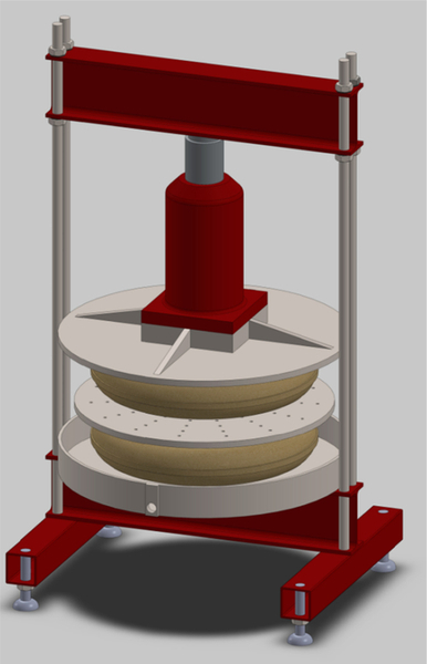
Plate 2.7Typical 3-D Model (Apple Press) [6]
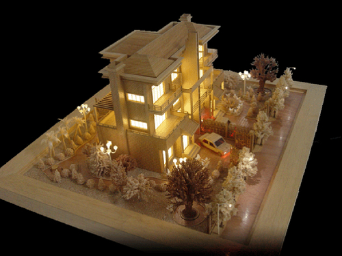
Plate 2.8Physical Architectural Model [2]
The concept design is often best shown as a visual representation. There is nothing that engages the human mind more than a good picture. This visual representation should, however, be more than just a picture; it should be annotated in a way that shows off the best features. It is actually a “point-of-sale” device created to entice the client.
A large amount of development money may ride on this presentation and convincing the client that the project is worthy of investment. The presentation should be geared toward the understanding of the client, who is likely to be an entrepreneur rather than an engineer. Information to which the client would be receptive is more financial and functions related, such as graphs, rather than stresses, strains, power consumption, and other technical details. The client would be more interested in overall performance and return on investment.
The client may be accompanied by other members of his or her team, such as the accountant, the production manager, and the chief designer. The accountant would ask questions such as, “How much will it cost?” The production manager will ask questions relating to whether the machine tools and manufacturing facilities are available. The chief designer will look carefully at the technicalities of the design and assure himself that due process has been completed in terms of stress analysis, materials selection, power consumption, and other practical details.
The client will look to his or her team to answer questions that are outside her field. The presentation and presenter should have answers to these questions so that the client can make a funding decision.
2.9.9 Concept design specification
The concept design specification (CDS) is developed at the same time as the concept design. Refer back to the classic design approach in Figure 2.7. The CDS should form a list of functions, performance data, requirements (such as fuel consumption) to make it function, envelope size, weight, and other technical details that will combine to give external people the opportunity to understand the new product.
Metrics should also be quoted, since these are the measurable elements by which the performance will be rated. Metrics here should be compared against those of the PDS, which were formulated directly from the brief. The two specifications should match. If there are any great differences, an iterative return to the solution creation process would be in order. The CDS should also cover an estimate of capital cost, maintenance, and probable running costs. Since the design specification can also be used as a selling tool, it could also incorporate chief benefits of the proposed new product.
As the concept developed during Phase 2 of the design process, the CDS should have been constantly compared to the PDS. The CDS should meet every point of the PDS. In practice this may not happen, but the differences should be so small as to be negligible. If there are large differences that are unworkable in the end product, the concept design should be reevaluated and modified to create a newly modified concept design and newly modified CDS.
A CDS for the conceptual apple press shown in Plate 2.7 is listed as follows:
Concept Design Specification for an Apple Press
Technical Details
• Cut apple capacity: 50 Ltr
• Load application: 10 tonne
• Applied pressure: 620 KN/m2
• Yield approximate: 65% liquid yield by volume
• Approximate mass: 100 kg
• Envelope size: height, 1.6 m; width, 0.8 m; depth, 0.8 m
• Throughput (approximately): 75 kg/hour
• Apple juice outflow (approximately): 50–60 Ltr/hour
Operation
1. Load two pressing bags with chopped apple.
2. Place the pressing bags on the base platen with the perforated plate between the two.
3. Insert the pressure plate on the top.
4. Insert the hydraulic jack between the pressure plate and the top beam.
5. Operate the jack handle.
6. Apple juice will flow from the bags into the catchment tray and out through the drain hole.
Maintenance
After completion of the pressing and before the press is packed away for the season, it requires hosing down to remove debris and congealed apple juice. The pressing bags could be washed, but it is recommended that new pressing bags be purchased.
Benefits
• Adjustable upper beam height to allow for a range of jacks
• Location ring on underside of upper beam (easy location of the jack)
• Jack can be operated by one person at approximately 1.2 m from the ground
• Easy insertion of fruit through the use of pressing bags
• Low-cost pressing bags easily obtainable
• Easy removal of pulp after pressing
• Perforated plate between bags to aid in pressure distribution
• Perforated plate assists flow to the collecting dish
• Guidance on pressure plate to prevent rotation during pressing
• Simple construction
• Low cost, estimated at £150
• Easily cleaned with a hosepipe
2.9.10 Sustainability
When material is extracted from the Earth, energy is required. Quite often this energy is derived from fossil-based fuel, which will have a “carbon footprint” environmental impact. Whatever the means of extracting and processing material for a product, it will take some form of energy, whether from a fossil-fuel source or from a natural, renewable source. To measure the environmental impact “sustainability” of the product, it is necessary to consider all the energy (embodied energy) used in extraction, processing, transport, usage, and eventually disposal. This calculation can be quite complicated and is discussed in a later chapter.
As an example of measurement of sustainability, use has been made of a CES Edu-Pack, which is a large database of materials and processes equipped with a very efficient tool for measuring embodied energy. The results can be seen in Figure 2.12. The graph shows the embodied energy subdivided into the main areas of energy usage: material processing, manufacture, transport, usage, disposal, and end-of-life potential, which covers recycling, reuse, refurbishment, and the like.
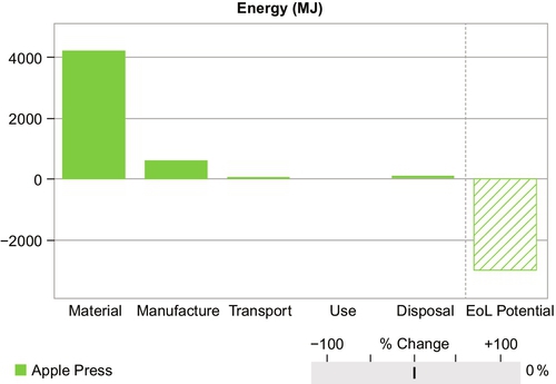
Figure 2.12 clearly shows the embodied energy for the apple press. It is clear that most of the energy is used in preparing the raw material. A little more is used in manufacture, and still more is used in transport. The apple press is manually powered, so in use it does not use direct energy. Disposal has been set as totally recycled, and it can be seen that even this element requires energy, but there is an enormous end-of-life potential since in recycling the material it replaces raw material that would otherwise be extracted from the Earth.
In the past very little consideration was given to sustainable elements of a product. Designers rarely looked at sourcing materials from an environmental point of view. Sourcing has always been driven by cost reduction. It is proposed that future concept designs and concept design specifications include an embodied energy value.
The designer has travailed through the investigation in Phase 1, and at this point, the end of Phase 2, has completed the generation and selection of solutions. This work has culminated in the creation of the concept design and the description of the concept specification. The next step, Phase 3, converts the concept design into a real “nuts and bolts” product.
The designer must realize that design is a complex business involving attempts to optimize a complicated set of relationships that will inevitably lead to a compromised solution.
Often elements and parameters are in conflict—for instance, high strength and low weight are necessary in many products, particularly so in aircraft construction. Compromise decisions have to be made here, since strength is an important feature of an aircraft structure, as is weight. There must be compromise between the two opposing elements.
There is seldom a unique solution to a design problem. Often several acceptable design schemes can be evolved to meet a given specification. The designer’s experience and the use of evaluation tools will assist in judging which solution is the most suitable.
It has been said that the designer has to think of everything. It is also true that the designer must have in mind several goals throughout the design progress. The designer must constantly ask the following questions:
• Can it be made?
• Does it work?
• Does it look good?
• Is it sustainable?
• What does it cost?
2.10 Phase 3
2.10.1 Phase 3 detail design: initial considerations
Phases 1 and 2 are really development phases that are mostly theoretical. It should be noted though that many hours from highly skilled individuals will have been injected into the project. Sometimes the design phase and easily consume 30% of the overall budget depending on the project.
During Phases 1 and 2, feasibility analysis will have been conducted so that a close approximation to the PDS could have been put forward as a final design concept. Stage 3 is where serious resources start to be used in the prototyping and manufacture phase.
To begin Phase 3, the designer must perform several duties at once. He must create the shape of each component and in many cases perform analysis that will guide him toward selecting the correct wall thicknesses, materials, finish, and so on. In some cases the designer may, for instance, create an image of a shaft within the CAD system, but in analyzing highly stressed parts of the shaft he may realize that these proportions have to be increased in size. The designer will then go back to the CAD image and change sizes. This iterative process may continue for every component within the product. The designer must ensure that before he commits the model to the manufacturing process, all aspects are correct. The consequence of not doing so would be wasted resources, time, and money.
This quest of ensuring that the detail design is correct is probably the most crucial phase of the whole design process. If there is a small mistake here, the dire consequence may result in breakage and could possibly cost someone’s life.
2.10.1.1 Example: accident with a rock drill
A rock-drilling rig similar to the one shown in Figure 2.13 operates with a 250 kg gearbox sliding up and down the mast. When the drill string sinks into the ground during the drilling operation, the drill operator unfastens the drill string from the gearbox and raises the gearbox to the top of the mast to insert another length of drill pipe. The hydraulic controls for raising and lowering the gearbox are at the side of the drill head.
Figure 2.13A Rock Drill of a Similar Type to the Example [1]
On one occasion the driller was lifting the whole drill string out of the ground. This amounted to a mass of approximately 2.5 tonnes, since it was lifting the mass of the gearbox plus the mass of the drill string. The whole 2.5 tonnes were pulled up the mast on a chain fastened via a chain anchor to a hydraulic ram. Since the chain anchor is a highly stressed component, it needs to be made of a high-strength material.
In this case the chain anchor parted and the whole 2.5 tonnes whistled down the mast, breaking the bottom of the mast and causing great damage to the rig. The fault was traced back to the design office, where the designer had merely inserted on the drawing a low-strength material. This seemingly innocuous mistake could have maimed or even killed the drill-rig operator. Fortunately he emerged uninjured but shaken.
People have different perceptions of design, but this incident highlights the fact that designers have a massive responsibility to “get it right.” Nothing can be left to chance, and every consequence must be considered.
2.10.2 Modeling and detail design approach
The method via which a designer approaches the detail design is often based on personal taste but is also dependent on industry practice.
Some designers might want to draw, in 2-D, the whole product with all the parts in place. This is called a layout drawing. A gearbox layout may mean the inclusion of gears, shaft, seals, bearings, and the like and will include annotation, sizes, and other notes, such as surface finish and tolerance bands. It will also include specifications of components. An example of a layout drawing is shown in the gearbox layout in Figure 2.14.
Figure 2.14Layout of Gearbox [1]
Consistent with emerging practices, a more modern approach is to build up the components in 3-D within an appropriate software system. Parts would be individually created as 3-D solid parts and then fitted together, rather like a physical build process. An example of the gearbox casing as a 3-D component is shown in Figure 2.15.
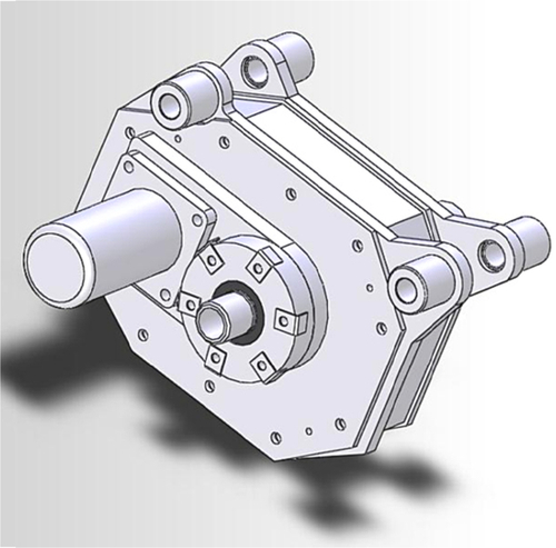
Figure 2.15Gearbox Casing as a Full 3-D Component [1]
Many component suppliers of items such as bearings, seals, and motors offer designers a free technical image download of their product. This could be 2-D or 3-D image, depending on the designer’s requirements.
Normally included in any 3-D software package is an interference interrogation tool, which alerts the designer should any parts overlap other parts. Once notified, the designer would then change the original component part model so that components do not occupy the same space as other components.
This assembly process creates in 3-D a complete product, achieving a similar function to the 2-D layout but with all the components modeled. The term modeling here means that all the components are of known size and have been saved in separate files. Due diligence now needs to be performed on each component. This includes stress analysis, tolerances application, surface finish, and correct material selection. Often a 3-D software package will include basic finite element generation for a particular component and the means to stress-analyze the component so that the designer can judge its strength. Other tools, such as dynamic analysis, thermal analysis, and fluid flow analysis, are also available. More specific and high-level software of this type can also be purchased as an add-on to the main 3-D software drafting package.
Should 2-D drawings be required, they can be quickly transformed from 3-D models into the drawings.
Similar information is required in the modern era, as was required when only 2-D drafting was available. The provision of the support data in such a system would have meant that the designer would manually create parts lists, materials specifications, and bought-out part specifications, to name just portion of the information required.
Within the 3-D software, once the model is formulated, the digital information can be used in many ways, with much of the information generated automatically. Parts lists are only one element of automatic information processing. Various departments in the manufacturing organization require data in different formats. The production team requires specific data, as does the marketing team. The digital 3-D software allows for manipulation and easy dissemination through e-mail and storage on remote Internet-based servers.
The analysis package in most 3-D drafting software allows for easy analysis of fairly complex systems. In the right hands, this is a very powerful tool. It can also be a tool that is too easy to use for a novice who perhaps does not completely understand the engineering. There have been some notable disasters where the fault has been traced back to the designer believing the results from the analysis without checking, a problem termed computer-aided failure, or CAF. The analysis algorithm will generate answers to some very complex questions, but if the information input is incorrect or the algorithm has been set up with errors, the outcome will be flawed no matter how complex the analysis. In the words of a notable academic at the University of Huddersfield in the United Kingdom, “Computers are stupid. They will only do what you tell them to do!” [4]
Any designer is advised to perform hand calculations or find some means of proving the analysis performed by the computer. Often this proof may be in the form of formal tests or merely informal experiments to prove the data from the analysis. The human intuitive, analytical mind applied to a clinical answer is usually required to make sense of the result and to spot deficiencies that the computer analysis alone isn’t equipped to understand.
2.10.3 The design process: information output
Information from the design process and the results of Phase 3, the detail design process, need to be disseminated in a form that can be readily understood.
Analytical results will help form the size and shape of components. They will give the designer the confidence and ability to define the shape and specify materials for particular components. In finalizing the size of a component—say, a shaft—the designer may also have applied commercially sought components such as bearings and seals. These will now be precisely specified and would normally include the company name and the company part number.
This is covered in detail in chapter 5, which discusses the processes and logic of detail design, drawing and communication.
2.11 Final Design Specification
With reference to the classic design approach illustrated in Figure 2.7, we can see that the design journey is almost complete. As the final model, drawing, and parts list is published to the rest of the company, the design team should be in a position to create the final design specification.
The FDS is a description of the product, including performance data and consumption data. It should include costings for prototypes and for production versions, though some of this information may be formulated in conjunction with other departments. The final design specification should match the product design specification and more precisely match the original brief that was identified by the client.
2.12 Product Specification
The product specification is a much cut-down list of performance data an example of which can be seen in Figure 2.16. It is data that the customer sees when he opens the product packaging. The product specification should give basic details of how the device performs and should indicate inputs, such as fuel, required to make it perform. Typically the product specification will include:
• Performance data
• Fuel input
• Energy efficiency
• Energy usage
• Connection details and specification
• Instructions on the use of the product
• Sundry data gleaned from the prototype and testing process
A typical product specification for a large commercial cooker could be as follows in Figure 2.16:
Figure 2.16Typical Product Specification for a Large Commercial Cooker [8]
2.13 Prototypes
In some cases it may be necessary to build prototypes for testing purposes. A prototype is the first full-scale, functional model and is often built to prove the concept and to confirm the claims of the design team. Testing highlights areas of uncertainty and gives feedback data to designers. Testing can show that the functioning of the device might not be as originally envisioned. In such a case, the iteration design process is applied and the elements that are lacking are modified. When a passenger vehicle is manufactured, for example, it is rigorously tested so that any deficiencies can be eradicated and data such as fuel consumption in urban areas or on motorways can be added to the product specification.
References
[1] A.D. Johnson (Senior Lecturer), University of Huddersfield, Huddersfield U.K., 2013.
[3] D. Warburton (Research Student), University of Huddersfield, Huddersfield U.K., 2012.
[4] R. Taylor (Senior Lecturer), University of Huddersfield, Huddersfield U.K., 2012.
[5] Scribd.com, www.scribd.com/doc/50459583/Example-Product-Design-Specification, 2012.
[6] M. Melia, K. Hinchliffe (Research Students), University of Huddersfield, Huddersfield U.K., 2012.
[7] C.L. Dym, P. Little, Engineering design: a project based introduction, Wiley, 2009.
[8] AGA Rangemaster Group, Clarence Street, Royal Leamington Spa, Warwickshire, CV31 2 AD, U.K.
[9] Granta Design: CES EduPack software, 2013.
[10] P. Lockwood, T. Armitage, J. Halpin, A. Ausin (Research Students), University of Huddersfield, Huddersfield U.K., 2012.
* A tolerance is a specified and allowed variation in a dimension. Physical dimensions cannot be machined perfectly so normally a “tolerance” is applied, e.g. 25 +/− 0.001 mm. This means the machinist can create the dimension to be between: 24.999 mm and 25.001 mm.