
The Tools of the Design Process and Management of Design
Abstract
This chapter examines the tools and methods that make up the design process. The development process is detailed in general terms, followed by a look at the need for a systematic approach to design. Design techniques including brainstorming, TILMAG, and the morphological box are considered in detail, and the chapter concludes with an overview of some relevant project management tools.
4.1 Introduction
4.1.1 Product development: an introduction
The economic success of manufacturing companies depends on their ability to identify the needs of customers and to create products that meet these needs. The products also have to be produced at a competitive cost.
Achieving these goals is a product development problem involving
• Marketing
• Design
• Manufacturing
• Sales
A product is something sold by an enterprise to its customers. Product development is the set of activities beginning with the perception of a market opportunity and ending in the production, sale, and delivery of the product. The money earned by selling the product to the customer allows the company to develop future products.
Product development, therefore, is the process of developing a new product from the initial perception of need to the final product.
4.1.2 Marketing
Marketing often facilitates the identification of product opportunities within the market. Marketing defines market segments and identified customer needs. Marketing also communicates between the manufacturing company and the customer regarding timing of product release, launching, prices, and promoting new products.
4.1.3 Design
The design function plays the lead role in defining the physical form of the product to best meet customer needs. The design function also generates information relating to many other aspects of the product prior to manufacture, postmanufacture, and after the product's life has expired. The design function therefore could include the following:
• Mechanical Engineering Design elements such as
• mechanical components
• electrical and control components
• software
• Industrial Design elements such as
• aesthetics
• ergonomics
• user interfaces
• color
• Sustainability elements such as
• material sourcing
• low-environmental-impact components
• usage impact
• longevity
• sustainable disposal
• Marketing and Sales components such as
• envelope size
• customer satisfaction
• warranty
• packaging
• installation
• after-sales service
4.1.4 Manufacturing
The manufacturing function is primarily responsible for implementing and operating the production system in order to produce the product. Manufacturing may also include purchase, distribution, and installation as well as the physical manufacture of the component. The manufacturing function should adhere to the specifications laid down by the design department, which should have researched components and considered the end function, something that manufacturing is unable to do because of lack of information. If sustainability is one of the major elements, then the design department should also specify the low-environmental-impact manufacturing environment.
4.1.5 Duration and cost of product development
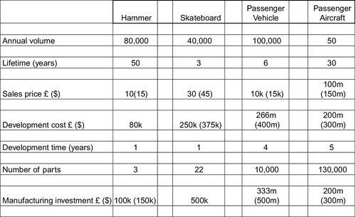
It is astounding how much time and money are required to develop a new product. In reality, very few products can be developed in less than a year and many require 3-5 years. Figure 4.1 shows four engineered products and Figure 4.2 shows the scale of the associated product development effort.

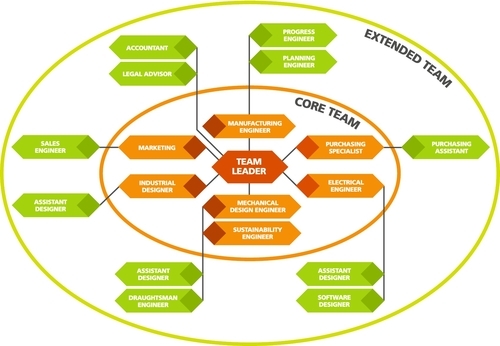
The cost of product development is roughly proportional to the number of people on the project team and to the duration of the project. There will certainly be expenses for the project team as there almost always will be expenses related to the acquisition of tooling and equipment for production. These expenses are incurred by a core team of specialists such as design engineers, purchasing specialists, marketing specialists, industrial designers, electronics designers, and other specialists deemed necessary to take the project forward. Furthermore, there are secondary personnel who can be counted within the extended team. They are people such as accountants, sales specialists, legal advisers, assistance personnel, and administrators.
Figure 4.3 shows a simplistic model combining the departments that might be involved in the product development process.
From the estimated values in the comparison chart shown in Figure 4.2, it can be seen that the more complex the product, the higher the development cost. This might seem obvious, but costs should be linked to the number of people involved in the development process. In fact, complex products need more specialist personnel input, which in itself will generate secondary duties such as legal advice and administration. Development costs are, therefore, extremely high: There is no earned value during the development process, yet there is potential for huge salary costs.
The composition of the product development team shown in Figure 4.3 highlights the need for personnel within the core design team as well as in the extended team. Typically, there needs to be a product champion who, in this case, is the team leader. It should also be pointed out that even in the simplest of projects, there needs to be a “Product Champion” who will drive the project and take responsibility for keeping it on schedule.
4.1.6 The challenges of product development
Developing a good product is difficult. Few companies are highly successful more often than not and these odds present a significant challenge for the product development team. Some of the characteristics that make product development challenging are described in the following sections.
4.1.7 Trade-offs
An aeroplane can be made lighter, but this action will probably increase the manufacturing cost. It is difficult to recognize, understand, and eventually manage such a trade-off. The Airbus A380 was such an enormous aircraft that weight and strength were of great concern. The traditional fuselage skin material was found to be unacceptably heavy when designed for appropriate strength. A composite form, aluminum alloy material, was therefore developed that met the strength and weight criteria. This exercise was very costly in terms of time and money.
4.1.8 Market dynamics
Technologies improve, customer preferences change, competitors introduce new products, and the economic environment shifts. Decision making in such a fluid environment can be extremely difficult and even disastrous. During the 1960s, aircraft manufacturers had a dilemma to face. They had to manage two functions:
• Build smaller and supersonic catering for a smaller but high-value number of passengers
• Build larger catering for a larger number of lower value passengers.
The supersonic airliner was, of course, the “Concorde.” The large aircraft became the Boeing 747. History records that the Concorde has been an exciting aircraft, but the trend of the market, which was correctly read by Boeing, was to provide large aircraft to transport hundreds of people.
4.1.9 Details
The choice between using screws or snap fasteners on the enclosure of a computer can have economic implications that could cost millions of dollars when applied to large-volume products. For example, a domestic bed, manufactured from a rectangular hollow section needed to be clad in plasticized MDF so that it was conducive to bedroom decor. The cladding designer applied over 50 screws to the unit to fix the fiber board to the bed frame. The fixing operation consisted in drilling the holes, inserting threaded nuts, assembling the cladding components, and tightening the screws. It was calculated that the operation would cost £150 per bed unit, which was 10% of the manufacturing cost. Clearly this was unacceptable. The solution was to use industrial double-sided foam tape, which could be applied quickly without drilling the frame or tightening screws. The cost of this was estimated to be £20 per bed.
4.1.10 Time pressure
Any one of the above development difficulties could be easily manageable by itself given plenty of time, but product development decisions must usually be made quickly and without complete information.
4.1.11 Economics
Developing, producing, and marketing a new product requires a large investment. To earn a reasonable return on this investment, the resulting product must be both appealing and relatively inexpensive to produce.
4.1.12 Organizational realities
In reality, some organizations exhibit characteristics that lead to dysfunctional product development teams. These characteristics may include the following.
4.1.12.1 Lack of team responsibility
Team leaders may continually intervene in the details of a project without fully understanding the basis of the team's decisions. In this case, the team leader does not feel that he is able to trust the judgment of his team. This is really a failing of the manager: he should have selected a better team, since he cannot keep from tinkering with the project. This is dangerous as the team leader may have only partial information, which could debase decisions. The technical designers, who are close to the problem, should be the actual decision makers.
4.1.12.2 Function allegiances
Wherever there is a group, the human condition generates politics. Representatives from marketing, design, or manufacturing may attempt to influence decisions in order to increase their own political standing, with complete disregard for the success of the product.
4.1.12.3 Inadequate resources
A team may be unable to complete development tasks effectively because of lack of staff; a mismatch of skills; or a lack of money, equipment, or tools.
4.1.12.4 Minimal cross functional expertise in the project team
Should key development decisions be made without the involvement of primary elements involved in the development process, problems may be caused in the later stages of development. For instance, an independent design decision could be made to increase the physical envelope of the product. Perhaps an electric motor protrudes from the product further than was originally envisaged. The extra volume does not manifest itself until the packaging stage of the project when it transpires that extra space is required for shipping. The difference means that only 300 units can fit inside a container while the original plan was to ship 500 units to be inside a single container. This obviously would increase costs that were hitherto unforeseen.
Most organizations will, at some stage, exhibit some of these characteristics. They may be stifling for the project so that the project development is rendered ineffective. The key to a successful product is to appoint a team leader, a “Product Champion,” who is skilled in dealing with people and in selecting the correct personnel.
4.2 Development Processes
4.2.1 Processes involved in product development
Most people are familiar with the idea of a physical process such as that used to bake a cake or to assemble an automobile.
In a similar way, the product development process becomes a sequence of steps or activities used to conceive a concept design and eventually leads to the commercialization of a product. Activities in the early stages of development are intellectual and organizational. Physical development is applied as late in the process as possible. While intellectual design activities can prove to be expensive, the build process is much more expensive, so delaying the build reduces expenditure.
Some organizations define and follow a precise and detailed development process, while others may not even be able to describe their process.
Furthermore, two organizations designing similar products will employ processes that are slightly different from each other. This may be due to personalities, the product team, skills mix, company resources, and so on.
It is, however, certain that whatever process is involved in product development, there will be a general approach to the process of design and manufacture. It is useful to define the elements of this development process as it will aid in analysis of the final product specification.
4.2.2 Quality assurance
A development process specifies the phases of a development project. The process also specifies points at which checks can be made on progress and quality. A careful selection of these checkpoints ensures quality in the resulting product and also furnishes the development team with checkpoints that prompt feedback to the client.
4.2.3 Coordination
Large projects, in particular, require a clearly articulated development process. Such a master plan defines the roles of each member of the development team and informs the members what their tasks are, when their contributions will be needed, and with whom they will need to exchange data and materials. In any group situation, team members usually require specific details regarding their tasks. It is always dangerous for a team leader to assume a task will be performed. Unless precisely allocated, it is likely the task will be left undone, each team member thinking that someone else will do it.
4.2.4 Planning
A development process contains natural milestones corresponding to the completion of each phase. The timing of these milestones anchors the schedule of the overall development project. These milestones are often used for reporting back to the client and are usually written into the contract. Successful completion of a milestone may also prompt the client to inject investment in order to move the project to the next phase.
4.2.5 Management
A planned development process can be set out with dates and activities and used as a specific guide for assessing the performance of the continuing development effort. By comparing the actual events to the established process, a manager can identify possible bottleneck areas. The manager must continually monitor project costs, personnel, techniques, and the technology employed. Any hold-ups in the development should be identified and accommodated.
4.2.6 Improvement
The careful documentation of an organization's development process often helps to identify opportunities for improvements and efficiency. At the completion of the project, it is beneficial for the team leaders and management team to “debrief” to analyze process flaws, problems, bottlenecks, shortages, overspends, etc. In this way, procedures may be improved so that future development projects become more efficient and, therefore, less costly.
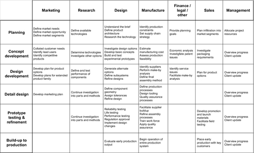
4.2.7 The generic product development process
The generic product development process consists of six phases (see Figure 4.4).
4.2.7.1 Generic development process: overview
The process begins with the planning phase. This is the link to advanced research and technology development activities. The output of the planning phase is necessary so that marketing can define the product and link the product specification to market needs. It is only at this point that the brief can be given to the design team to begin the concept development phase.
The initial development process considers the creation of a wide set of alternative product concepts, whose benefits are then explored so that the alternatives are subsequently narrowed down. As the design investigation focuses on a narrowing number of concepts, the specification of the product expands until reliability and repeatability can be predicted in a single new concept.
The design development process is an information-processing system. The process begins with inputs such as the objectives, requirements, constraints, and awareness of the capabilities of available technologies. The various activities during the development process use the information to formulate specifications and concepts and eventually design details for manufacture and physical development. The six phases of the generic development process are discussed next.
4.2.7.2 Planning
This phase begins with a general strategy (usually corporate strategy) and includes an assessment of market needs and the technology available to meet those needs. Often the company is already manufacturing goods for a particular industry and would fairly easily be able to apply the technology in which it is expert. In the development of new products, however, the progress of a company is always dependent on its willingness to apply new technologies. In any new development, current and new technologies should be considered when the company is attempting to meet market needs. The output of this planning phase is the project mission statement, which, among other things, includes a project definition.
The planning phase really outlines a general design specification and includes the following:
• Mission statement
• Requirements (market needs)
• Constraints
• Identification of technologies
• Target market
• Business goals
• Key assumptions
Perhaps the most important element in the planning phase is the creation of the Product Design Specification (PDS). This is really the route map given to the designers so that they can match the new product to the market needs.
4.2.7.3 Concept development
In this phase, the needs of the target market are identified from the Product Design Specification. The design team generates several design concepts, which are then evaluated for “best fit” with the market needs and PDS. Some proposed solutions will be closer to the market needs than others. The evaluation process selects one or more concepts for further development and possible prototype build and testing.
When a concept is generated, it should be accompanied by a Concept Specification that contains a refined description of the form, function, and features of a product. Within the concept specification, there should also be a feasibility study, an analysis of the competition, and an economic justification for the project. The Concept Specification should closely match the PDS and, hence, the market requirements.
Once the concept has been defined, it may be used to market the product to entrepreneurs or the company’s board of directors in order to raise investment money for further development.
4.2.7.4 Design development
After creation of the concept or several optional concepts, the design development phase considers the practicalities of design and manufacture. The development plan identifies probable departments such as manufacturing, design, and purchase. The product is also usually broken down into its composite parts. For instance, a car would be broken down into body, suspension, engine, wheels, gearbox, etc. This would enable each subsystem to be analyzed and designed separately.
The result of design development phase would closely specify each product’s subsystems and generate a final assembly process. Information gleaned during this particular exercise can be used to convert the concept into real-life materials.
4.2.7.5 Detail design
The detail design phase defines the complete specification of the geometry, materials, and tolerances of all the parts through the provision of detail drawings, assembly drawings, and general assembly drawings. It also includes the specification of all the bought-out parts complete with preferred suppliers and component designations. The result of this phase is the complete and precise physical description of all the parts in the product. These drawings can then be issued to the manufacturing function for precise manufacture and assembly.
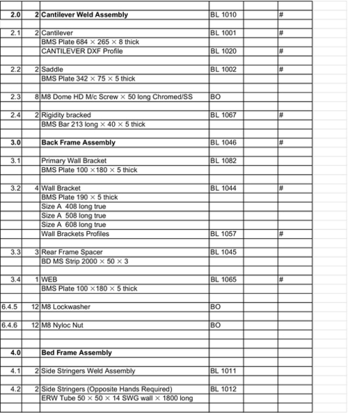
The detail drawings require an index in order to be understood and coordinated. Along with the detail drawings, therefore, there should be a general parts list, which will act as a “map” and precisely instruct the manufacturing function to group components into assemblies and, further, assemblies into the full product. Figure 4.5 shows a portion of a typical parts list, which lists all the parts along with raw material sizes and specifications. It should be noted that this particular parts list shows elements of three subassemblies.
The detail design phase takes the concept design and applies it to the material components and, in effect, plans the manufacture and assembly of the product. During this process, the designers consider the selection of materials, manufacturing techniques, machine tools, and processes such as forging, injection molding, and casting. Further processes such as chromium plating and painting are added to the specification.
It must be emphasized here that every single component and process required to complete the product and which, therefore, adds cost to the product requires a detailed specification at this stage.
The detail design often relates to the product, but once the product has been defined precisely in terms of technical drawings, other manufacturing elements may be pursued such as specialist machine tools, jigs, and other specialist manufacturing equipment.
4.2.7.6 Prototype testing and refinement
Almost all products require testing and further refinement. Any new product should be carefully tested to match the specifications and requirements originally laid down. In some cases, manufacturers allow a protracted period for this so that durability and longevity can be ensured through the tests.
The phase involves the construction and evaluation of many reproduced versions of the product.
Early prototypes are usually produced as close to the production version as possible but, in many cases, the first prototype is several steps away from the production version. The first prototypes are required to prove that the device functions as predicted by the design team. Many development refinements may have to be made in order to creep closer to the production version.
Evaluation of a prototype involves assessing the following elements:
• Functional requirements (does it work as it should?)
• Manufacturing requirements (can it be manufactured easily?)
• Assembly requirements (can it be assembled efficiently?)
• Cost requirements (can it be manufactured to a target cost?)
• Serviceability (can it be serviced to protract its life?)
The first prototype is important as each of the mentioned elements can be analyzed and improvements instigated. The development of a new product is a learning process and the first prototype is a crucial step. Improved prototypes can then be built from the initial lessons learned.
Later prototypes are usually much nearer the production version and are often called “preproduction prototypes.” These secondary prototypes are usually used to evaluate the product’s performance and reliability prior to the manufacture of the production version tooling. Later prototypes are subjected to the same scrutiny as the first prototype, each evaluation adding to the wealth of knowledge leading to the final product.
4.2.7.7 Production build-up
During this phase, the product is made using the intended production system. The purpose of the ramp-up is to train the work force and to work out any remaining problems in the production processes. Furthermore, logistics system is evaluated, perhaps to alert satellite storage depots and book appropriate transport.
Products produced during this phase are sometimes supplied to preferred customers so that they can be carefully evaluated to identify any remaining flaws.
In 1976, the Ford Fiesta was named “The Bobcat.” It was supplied to various agencies throughout the UK for testing and discovering teething problems. In fact, even after the Fiesta was launched in 1977, there were problems with leakage through the air intake grill resulting in a major recall to effect repairs.
At some point, the production build-up is converted to the full-production version. Usually, the launch date is the trigger point for converting the preproduction version to the full-production version.
4.2.8 The approach to concept development
Concept development involves many interrelated activities from the investigation and understanding of customer needs to the generation of possible solutions. Eventually, the specification of the best solution for manufacture is formulated. There is usually an element of research throughout the process, from the start of the design to the manufacture. The research is obviously more intensive at the beginning of the design project and may involve the research for new technical solutions and new components, as well as information research.
Rarely does the entire process proceed in a purely sequential fashion. It is unusual to complete one task before continuing with the next.
In practice, activities may overlap in time, running parallel to one another. For instance, at the beginning of a project, the search for a suitable internal combustion engine may be initiated at the same time as that for a screw compressor. Design is an iterative process requiring new information before the design can progress. When a new piece of information is gleaned, the design may have to be changed. Such is the case when the designer creates a design with, say, a hydraulic ram. Several days after the initial enquiry to locate a particular hydraulic ram, the designer may receive technical information showing that the original ram enclosure is not large enough. The designer has then to reformulate the design in order to accommodate the ram design that can be obtained.
New information may enter the design arena even while the design is ongoing, resulting in the backtracking of the design when new information becomes available or results are learned through experiment. Unfortunately, the nature of design and the reception of information often cause the design team to step back to repeat an earlier activity before proceeding.
This repetition and backtracking of activities is known as “development iteration.”
A rock drilling company was tasked to design a rock drill (to drill water well boreholes) at normal elevations from sea level up to an elevation of 3000 m. The drill rig was designed with a particular naturally aspirated engine to give enough power for this elevation. The customer then reapplied the design specification so that the rig would be capable of working in the Himalayas at elevations of 5000 m. At this altitude, there is a great deal of power loss because of the oxygen-depleted atmosphere.
The design team then had to backtrack to select a new engine of greater power, which delivered the performance required by the original specification. This process involved backtracking to redesign other elements of the design, such as larger fuel tanks, strengthened chassis, larger volume engine bay, new subchassis, new engine mounts, and stronger drive couplings.
The process of concept development includes several key activities, which are discussed in the following sections.
4.2.8.1 Identifying customer needs
It is essential that the customer’s needs are met. Though it may be difficult to meet all the customer's needs, the product must appeal to the market in order to sell. There would be no point in going through the design process if there was no market for the product.
The goal of this activity, therefore, is to understand the customer's needs and to effectively communicate them to the development team. Once the customer's needs have been identified, they need to be collated in a list of requirements organized in a hierarchical order. These needs may be weighted relative to the perceived importance of each requirement.
The Product Design Specification (PDS) provides a precise description of what the product has to achieve, and converts the customer's needs into technical terms and creates targets from the very outset of the project.
These specifications may be fairly broad at the beginning of the project but after proceeding through several iterations and stages of the development process, these specifications become more and more refined.
At the beginnings of the project, the brief is perhaps no more than a target wish list and can be considered a list of requirements. This initial specification builds into a more precise target, which, of course, is the Product Design Specification (PDS). As a design progresses, other specifications mark strategic points within the design process. The progressive list of specifications is as follows:
• Brief
• Product Design Specification (PDS)
• Concept Specification
• Final Design Specification
• Product Specification
The Final Design Specification (FDS), however, is a precise description of what the product can achieve. The FDS may be quite lengthy, but it is actually for internal audit so that the technical design team along with the other functions, such as marketing and sales, can precisely match the product outcomes to the original market requirements.
The Final Design Specification is often far too complex to accompany the product into the marketplace. It could confuse the customer and, at worst, could give away vital information to the competition. From the Final Design Specification, a Product Specification is formulated. This is a shortened version giving only the information that is relevant to the functioning of the product.
An example of a Product Specification, which is the specification for an electric arc welder, is shown in Figure 4.6. It gives the power supply voltage, the welding current range, etc. Figure 4.7 is an excerpt from the handbook of a CD player. It gives the kind of disc format, the voltage, the wow and flutter values, volume levels, etc.
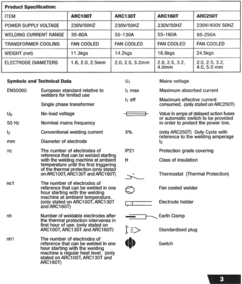

Both these specifications possess the bare minimum of information to allow the customer to make an informed choice, and restrict the information competitors may use.
4.2.8.2 Subtasks within the process of concept development
The process of concept development can be subdivided into smaller tasks. These are discussed in brief in the following sections.
4.2.8.2.1 Concept generation
The goal of concept generation is to thoroughly explore the range of solutions and match them with the particular customer needs.
Concept generation involves a mixture of external research, creative problem solving, and systematic exploration. There may be several design elements which may be assembled into a complete product.
For a passenger vehicle, there might be such elements as internal combustion engine design, suspension design, body design, and brakes design. Each element needs to be designed in parallel, resulting in a large volume of possible solutions. Overall, there may be up to 20 different preliminary concepts (minimum 3). The design team should break each one down into its subelements but should have an overview of how the elements fit together.
4.2.8.2.2 Concept selection
This is the activity that selects the very best of the concepts generated thus far. Proposed solutions may often be combined and this usually requires several iterations before an acceptable concept is created and finally considered suitable for physical development. There are several solution generation processes and tools that can aid in this process; they are discussed later in this chapter.
4.2.8.2.3 Concept testing
It is usual to emerge from the concept generation and selection stages with at least one seemingly viable concept and sometimes with several of them. Concept Specifications should be generated for each concept and compared with the Product Design Specification. The PDS represents the technical values relating to the market needs. The Concept Specification should closely match the PDS.
These comparative tests may also be related to a market research plan or could be further enhanced by feedback from a controlled selected audience.
4.2.8.2.4 Setting final specifications
In the final stages of physical development, the PDS is revisited after the concept has been selected and tested. The product requires to be rigorously matched to the needs of the customer, and in the process, trade-offs, usually between cost, sustainability, and performance, and limitations are identified.
4.2.8.2.5 Project planning
This is one of the primary activities after the brief has been received. The team create a detailed development schedule for what they believe to be the product, devise a strategy to minimize the development time, and identify the resources required to complete the project. This element is required before an economic analysis can be applied to the product and should have flexibility built in, as the development of the project could be in several directions, requiring a flexible plan.
4.2.8.2.6 Economic analysis
An early economic analysis is often performed before the project begins. This is necessary to secure appropriate funds but may prove difficult if the product is new and does not yet exist. However, when there is a rational concept to analyze, it is necessary to predict development and manufacturing costs. As the project becomes more developed and the outcome becomes more predictable, it becomes easier to predict the economic cost.
4.2.8.2.7 Benchmarking of competitive products
Research related to the main competition is absolutely essential as this provides an indication of the level of complexity of the new product and may give the design team new ideas. Benchmarking is, therefore, essential if the new product is to beat the level of technology of the competitors.
4.2.8.2.8 Modeling and prototyping
Every stage of the concept development process involves various forms of models and prototypes. They may include the early “proof of concept” models or prototypes, which assist the development team to demonstrate feasibility. These models may also be scale models, such as those used by architects to demonstrate street plans.
Some models may be shown to customers to evaluate ergonomics and style. There are many other forms of models such as financial models and design analysis models that can also be introduced.
4.3 Systematic Approach to Design
The principal role of the designer is that of an originator in the process of creating new products. The initial task is to identify the “primary need” for the product, which is really a statement of the design problem. In large organizations, the primary need may be established by the marketing function, who will provide the basic need specification. In other cases, it may be the designer himself who assesses the primary need in order to develop the design.
4.3.1 The primary need
The primary need arises from various sources:
• An update in the process of manufacture
• The exploitation of new technology
• The need to improve on the product of a competitor
• The need for a new product following changes in legislation
• The need for accessories following a new development (mobile phone accessories)
• The requirement of a new product
It is important for the designer to understand that the requirements and needs set out by the customer may not be the actual requirement. Customers often have their own solutions, which they are enthusiastic to impart to the designer.
For example, one of the customer stated true needs for a particular project may show that a new machine is required to test a full vehicle under fully loaded conditions. This customer requirement could possibly be the result of his ignorance of test techniques. Investigation by test specialists may reveal that the tests need to be conducted only on a quarter car model, which would considerably reduce test equipment costs.
4.3.2 The solution process
Design solutions are not merely plucked out of thin air. There is a certain progressive process that, when applied, leads the designer through various iterations to create an optimum concept. The complete Systematic Design Technique can be seen in Chapter 2, Figure 2.7. A simplified version leading to the concept stage of the design can be seen in Figure 4.8.
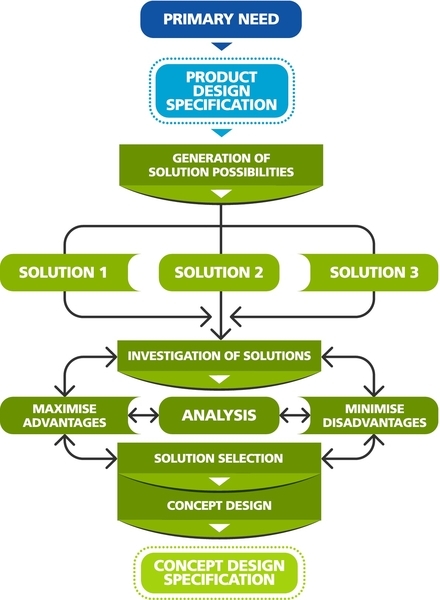
Often the primary need is conveyed as a set of verbal statements, which then need to be converted into technical parameters through the Product Design Specification. The PDS provides the parameters from which solutions can be generated. Normally, the designer would be expected to provide between three and five solutions, depending on the project.
Each proposed solution requires a detailed investigation weighing the advantages against the disadvantages and ensuring that the optimum solution is gained. Often, a mathematical analysis is required to ensure that the proposed solutions possess the technical parameters required by the PDS. After the rigorous investigative and analytical process, the outcome should be a single solution, which becomes the Concept Design. The technical parameters are used to create the Concept Design Specification. The successful development of the design to the concept stage would show a close comparison between the Concept Design Specification and the PDS.
This systematic approach can be considered a form of stocktaking and will provide answers to such elements as
• Method of device operation
• Production procedures
• Power flow techniques and methods
• Method of control
4.3.3 Investigation, synthesis, and analysis
4.3.3.1 Investigation
When taking up the design challenge, the designer needs to apply a clear train of thought and to develop an investigative technique. Investigation is extremely important for the designer to familiarize himself with the requirements of the brief and any technological developments that may be applied to the new design proposals.
Though designers may be specialists in particular areas of industry, investigation at the start of each new design project will eradicate complacency. Design evolution cannot take place without investigation, which will naturally lead to the discovery of new materials, processes, and components.
The design of the aircraft has been the subject of intensive investigation. When the Wright brothers made their first flight in 1903, intensive investigation resulted in what was effectively a powered kite. Further investigation by scientists and engineers from all over the world resulted in huge leaps forward in the development of heavier-than-air flying machines. One of the landmark achievements resulting from this investigation and design development was witnessed in 1947 when Chuck Yeager became the first man to fly faster than the speed of sound. This was a mere 44 years after the Wright brothers first flew their powered aircraft.
4.3.3.2 Synthesis
In some circles, the act of design is considered to be artistic. In fact, the act of design is really artistic science and is composed of two elements:
• Synthesis
• Analysis
Analysis is dealt with later; however, it is an important part of the design process as it tests the physics and feasibility of the design through analytical means.
Synthesis is the artistic or creative process that the designer uses, first to imagine and then to model through sketches or drawings, or using physical model.
Synthesis involves collecting design information, ideas, appropriate technologies, possible components, etc. The sketching and modeling of alternative proposals formulates the design in the mind of the designer, allowing it to be shared with colleagues or clients. This synthesis is essential at the beginning of a project to integrate an enormous breadth of data. In effect, synthesizing the information is similar to filtering the most important data for use within the proposed solutions.
It is common to synthesize a minimum of three proposed solutions so that detailed comparisons can be made. A synthesized solution, when communicated through a sketch or a model, can then be analyzed for feasibility and function.
During the synthesization process, the designer’s judgment plays an enormous role. Judgment is often based on previous experience and a “feel” for the requirements of the product. For instance, in the design of a new bicycle, the personal experience of the designer would tell him that a lightweight frame was essential and could not be manufactured from an “I” section girder. The more experienced designer will possess a more refined judgment.
A note of caution needs to be issued here: If a synthesized design is based purely on judgment, the result will be overdesign or “if it looks right it is right.” When employing judgment, even the most experienced designers will tend to overdesign. Synthesis, therefore, has to be combined with analysis, which will refine the synthesized design into a workable and feasible one.
4.3.3.3 Example: hand mounted cycle mirror
A hand mounted cycle mirror that was light weight and unobtrusive was to be designed. The mirror was to be fitted to the cyclists right or left hand depending on the side of the road he/she was cycling.
The investigation led the designer to first consider mirror shapes and the ergonomics of attachment to the cyclists hand, which quickly led to an investigation of methods of manufacture. Injection molding was identified as the most appropriate manufacturing method. The final injection molded concept, can be seen in Figure 4.11.
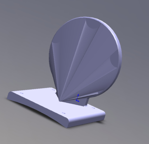
Figure 4.11Injection Molded Mirror Mount for Cyclists [4].
The investigation of the product requirements led the designer to consider such elements as ergonomics of the hand, comfort, strap types, strength, ease of manufacture, and cost of manufacture. The design synthesis evolution can be seen in Figures 4.9 and 4.10. These figures show the thought processes of the designer as he blended the design requirements into one unit.
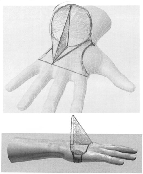
Figure 4.9Injection Molded Cyclist Hand Mounted Mirror [4].
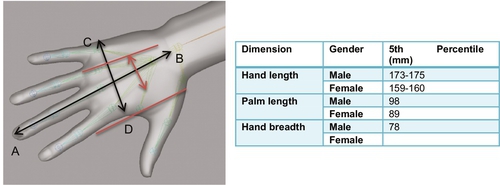
Figure 4.10Ergonomic Investigation for the Hand Mount Development [4].
The design of the cable tidy clearly indicates the evolution of the design using the synthesization process. It also indicates that synthesization has to take place in parallel with investigation and analysis.
4.3.4 Design evaluation
Evaluation of the design is always done as the design evolves but is often formalized using a systematic process. Analytical tools such as 3D CAD applied finite element analysis can be used to great effect in evaluating the synthesized shape as shown in figure 4.12. The systematic process of comparison and evaluation may be undertaken by using a points system or some sort of ranking technique. After Synthesis, analysis and evaluation the 3D CAD system allows a “photo-realistic” 3D image to be generated as shown in figure 4.13.
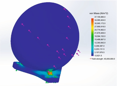
Figure 4.12Strength Analysis Using Finite Element Analysis Methods [4].

Figure 4.13The Final Version of the Hand Mounted Cycle Mirror [4].
Evaluation points of such techniques could include the following:
• Fulfillment of function
• Reliability
• Cost
• Sustainability
• Serviceability
• Life expectancy
• Ease of maintenance
• Ease of manufacture
• Efficiency of operation
• Simplicity of layout
Ideally, the method of evaluation should be kept simple. The method of morphological analysis is an excellent tool and is very effective when used properly, but care should be taken because it can easily be subconsciously skewed. More importantly, it could be laid open to abuse were results to be manipulated to give the advantage to a favored design.
The specification of the concepts in sketch form focuses the designer on clearer, more concise thinking patterns. These designs can now be systematically evaluated using the tools shown in Figure 4.14.
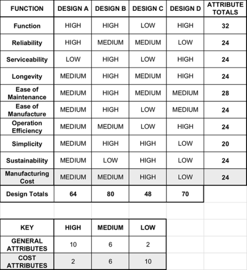
Figure 4.14Morphological Table of Design Feature Ratings [2].
The chart in Figure 4.14 shows the attribute totals, which indicate the general achievement of each of the designs. It should be noted that cost attributes have been set as inversely proportional to the general attributes.
It can be seen that most designs offer a similar value of achievement; however, they should be treated with great care as some designs offer a reduced level of the particular requirement. For instance, design C has a very low level of function, ease of manufacture, and operational efficiency even though some elements, such as simplicity, are high. Any or all of these elements could eliminate this particular design from the selection.
Perhaps the more important parameters are those indicated by the design totals. They are the scores that indicate the best options. Scoring in such a fashion can be subjective and may lead to subconscious favoritism. It is suggested that of the better options, two or three designs are analyzed closely to ensure that important features are included in the final selection.
The chart indicates that design B, scoring 80 points, is the best, closely followed by design D at 70 points. On analyzing the individual scores, it can be seen that there is a low sustainability score for design B. If sustainability has been given a high priority, then clearly this design does not meet the requirements.
The next high-scoring design is design D, scoring 70 points. This design has a low sustainability score and may suffer from the same problem as design B, but this design also has the advantage of a low manufacturing cost, which may offset the low sustainability score. Thus, in this situation, the second-highest scoring design appears to be the optimum selection.
This exercise highlights the fact that design is always a compromise and the designer has to select the best value parameters to create an optimum design. The morphological chart is an excellent tool but needs to be operated carefully.
Larger and more complex designs may require more detailed attention and perhaps may have to be broken down into individual assemblies, each one studied in a similar manner.
4.3.5 Analysis
Analysis can take several forms and requires the application of both practical and theoretical knowledge. It will include elements such as the following:
• Consideration of manufacturing tolerances (accuracy)
• The shape of the component
• Ease of maintenance
• Ergonomics
• Strength considerations (e.g., stress analysis)
• Envelope size
Analysis often involves some form of numerical calculation. The function of analysis is to define the parameters and operation of the design. For instance, an analysis of ergonomics when applied to a machine tool will consider the position of the controls as well as the forces and directions relating to how the human form may operate such elements. These parameters are often defined numerically.
In the design of an automatic mechanical vehicle parking system, the envelope of a typical vehicle had to be defined before the overall 200-space car park could be designed.
Perhaps the most obvious analytical element of design is consideration of the strengths of the components, where stress analysis defines their strength and eventual size and shape. Analysis such as this is not limited to just strengths. Some components demand dynamic, thermal, and fluid flow analytical techniques to predict performance and ensure correct function.
Synthesis and analytical techniques are often performed at the same time. A designer may consider the shape of the components alongside analytical calculations to define its feasibility. Analysis, therefore, is essential to the completion of design as it complements the artistic aspects of design creation.
4.3.6 Iterative design procedure
In mathematics, an iterative procedure is one in which an approximate solution is initially guessed and then fed into an iterative formula revealing a much more accurate solution. The improved solution is treated using the same procedure to reveal an even better solution. The process is continued until a solution with the required accuracy is achieved.
A systematic iterative design follows a similar path and assumes that even the best design concepts may need to be modified, both during the development process and after the launch. The trigger for an iterative process is often new information, perhaps from the marketplace, new technology, new components, or the results of analysis.
Even the modified version of components, especially complex components, may need further improvement and development until the ideal solution is achieved.
An effective iteration process, shown later in Figure 4.15, ensures that successive iterations are less involved than the previous one. The iteration diagram illustrates the iterative design procedure in the form of a flowchart, the feedback loops indicating the return to the start of the iteration.
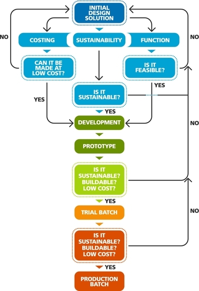
Figure 4.15The Iterative Design Procedure [2].
While the iterative process is extremely useful and necessary, the designer must realize that he cannot continually keep redesigning. The process has to end when it is judged that the goal has been reached. The danger is that the process can continue ad infinitum, incurring a great deal of time, effort, and cost. There must, therefore, be limitations as to the number of iterations and redesign.
The design of a bed lifting system resulted in many good ideas over which the team enthused. The lead designer reminded the rest of the team to store the ideas for later refinement after the base model had been converted into a product. If the team leader had allowed these modifications to be researched, excessive time would have been spent in refinement, resulting in a sophisticated but costly device. The main goal here was to create a basic “without-frills” product.
Ideally, redesign and reiteration must be limited to minor modifications and should be tackled at the earliest opportunity. It is easy for designers to be carried away; however, discipline and practice should be employed to keep the project moving toward the primary goal.
Good liaison between departments is a critical factor and the method of “redesign for cost” or “redesign for sustainability” should be adopted. These two concepts should be borne in mind from the very beginning of the project; however, in the later stages of the project prior to manufacture, this process should involve only minor adjustments, resulting, for example, in just switching to a different supplier for a bought-out item.
Redesign for function may be merely a simple alteration of a design sketch after tentative development tests have been conducted. For instance, this could mean changing the fixing location for a hydraulic ram.
After-sales redesign can be undertaken most effectively by considering feedback performance from a trial batch of production prototypes. Small trial batches are often supplied to a limited number of established customers for trials. The Ford Bobcat was a good example of this. Trial batches were sent out to trusted users who fed back useful field trial information. The Ford Bobcat eventually became the Ford Fiesta.
4.3.7 Design evolution
Design evolution takes place over many years. A product is launched in the market and immediately people try to improve it. There are hundreds of examples of design evolution. The bicycle started its life as a wooden contraption that was pushed along by the rider's feet. There were several evolutionary designs proposed such as the “Penny Farthing,” but the formula of the modern bicycle emerged only when the pedal crank was connected to the drive axle by a roller chain. Modern evolution has kept the general format but improved the materials, brakes, suspension, and tires and reduced the overall weight.
The same evolutionary cycle can be cited for the motor vehicle, which started out as a horseless carriage fitted with a motor. The evolution of the vehicle has brought about improved suspension, tires, engines, and much more than can be mentioned here. Perhaps the main evolutionary successes for the motor car are improved speed and improved safety.
4.3.8 Specification (customer needs)
It is rare for a product to be designed without a purpose in mind; it usually requires an instruction to produce a solution. This instruction is really the “customer needs statement,” which may be informal but quite often is likely to be set out as a specification of technical requirements. This may be supplied either by the customer or by the marketing department.
The British Standard issues recommendations for the preparation of specifications, contained in its document PD 6112. Using the British Standard, the specifications for the example of a simple electrical cable tidy may be written as follows:
1. Title
A wall-mounted device for safely storing coiled electrical cable in a domestic environment.
2. History and Background Information
It has been found necessary to introduce a device that can be wall mounted in a domestic environment, can safely hold up to 50 m of coiled electrical cable, and can capture the cable, holding it in situ until manually released. The device should be simple enough to be manufactured in tens of thousands at a low cost.
3. Scope of Specifications
The design must incorporate a hook system with a retention device, thereby ensuring the cable will not spill out when unattended. The reason for this is that it can be expected that there may be some abuse whereby more than 50 m of cable are applied to the device.
The device must be made from materials that are easily available and sustainable.
4. Definitions
Cable Tidy: a hook device mounted on a wall that will enable the storage of 50 m of standard electrical cable.
Retention Device: some form of device or clip that will prevent the cable from spilling out.
5. Conditions of Use
The device must be static when fixed to the wall and have the strength to hold over 50 m of standard electrical cable.
There must be no environmental health hazard caused by any feature of the device during or after manufacture.
6. Characteristics
The cable tidy should be lightweight and manufactured from readily available materials that are low cost and have a low-environmental impact. The device should be suitably finished so that it complies with the expectations of the customer when fitted within the home.
7. Reliability
The device should have an intended life of between 5 and 10 years and should possess a safety factor for three times the intended load.
8. Servicing Features
The device should be of a design such that it can be fitted in the domestic environment by someone with relatively low DIY expertise. Once in position, the device should need no further servicing.
4.3.9 Secondary needs
Successful design development focuses on primary needs such as function and cost. The designer is also tasked with considering the secondary needs while in the process of creating the primary needs. Primary needs ensure the design works, while secondary needs make the design comfortable. Sometimes the designer may give priority to the primary needs, leaving the secondary needs to be created afterward. Commonly, however, secondary needs are considered alongside primary needs. The following is a list of some of the typical secondary needs:
• Reliability
• Serviceability
• Ergonomics and anthropometrics
• Aesthetics
• Safety
• Economics
4.3.10 Design life cycle
A product generally goes through a life cycle, starting from the point of its initiation into the market until the need arises to redesign it in compliance with the latest market requirements. There are many reasons why a product may fall out of favor in the market. The product may become obsolete because of a change in technology or a change in methods or it simply falls out of fashion. Figure 4.16 shows a product’s typical life cycle from market insertion to obsolescence.
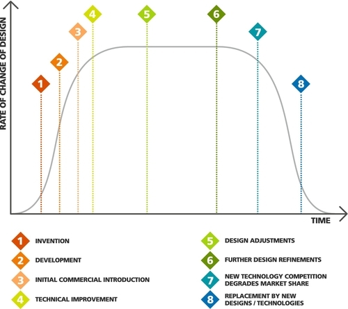
Figure 4.16Typical Product Life Cycle [2].
The life cycle shown is fairly typical of many products but it fits the technology associated with still photography equipment (cameras) very closely. The whole life cycle of camera technology using light-sensitive film has taken perhaps 120 years. Originally, the picture was captured using silver halide spread in a film over a glass plate. This had to be “developed” so that the image could be seen. This took the product development to position 3 on the curve.
The next major technical development at position 4 was that of using celluloid film as the carrier for the silver halide. Improvements in camera technology, camera efficiency, lenses, etc., enhanced the technology until cameras using celluloid film reached their technological peak at position 6. At this position, digital technology became more popular, making photography much simpler for the masses.
Film camera technology thereafter began to lose its position in the marketplace to digital camera technology until at position 8, 95% of the cameras sold were digital cameras.
Improvements in technology and methods of picture capture made film camera technology obsolete.
4.3.11 Invention and lateral thinking
A new product sparked by pure inventive genius is extremely rare. Normally, an idea leading to a product is generated by some occurrence or need, which then initiates a design concept.
The concept of “necessity is the mother of invention” is very real, indeed. There are, however, many tools that stimulate the fostering of ideas and concepts once the need has been exposed. One such method is lateral thinking. There are many others, which will be covered later.
An inventor is often a freethinking individual who is not fettered by a discipline such as engineering. Thought processes are very different. The inventor will consider an idea and try and make it work. The engineer may consider the same idea and discard it after considering engineering options. It is difficult to say who is correct since both points of view have their merits. It is true, however, that inventors have greatly contributed to products that are now enjoyed worldwide.
The free-thinking inventor is usually capable of lateral thinking, often called “thinking outside the box.” This usually involves considering options from many technologies rather than being limited by the technology surrounding one discipline.
4.4 Design Methods
4.4.1 The tools of creativity
A team of designers requires tools to boost creative thinking and to generate new and different ideas. Such tools also:
• Establish a creative environment
• Create a common vocabulary
• Provide new ways to understand all elements of the problem encouraging breakthrough solutions
• Incorporate the ideas and talents of the whole team
• Inject enthusiasm and energy into solving tough problems
There are several systemic tools available to teams of designers. They are discussed in the following sections.
4.4.2 Heuristic redefinition
How would one climb a mountain that has not yet been conquered? The difficulty is that there are no maps or natural pathways to the summit.
One might consider the best routes while viewing the mountain from a distance or perhaps by studying the mountain's terrain on a satellite image. This investigation would help to select the most convenient ascent to the summit. There are many different methods of ascending a mountain such as climbing on foot, parachuting from a great height, reaching the summit via helicopter, and so on. These are all methods of realizing the goal, but the first step is to define the goal before trying to reach it.
Often the seeds of a solution are buried in an efficient definition of the problem itself.
4.4.2.1 Example
When NASA first developed the space shuttle heat shield, they sent out a definition along the following: “There is a requirement for a material which will withstand 15,000 degrees centigrade.”
There is no material on earth that can withstand this temperature. After several rejections, the definition of the problem was changed as follows:
There is a requirement for a system which can accommodate 15,000 degrees centigrade.
This new definition allowed design teams the freedom to develop a revolutionary heat shield that combined a heat dissipation system with specialist materials.
The Heuristic Redefinition Tool can often free designers from a fixed view, to propagate a free-thinking format.
4.4.2.2 Heuristic redefinition tool definition
Heuristic Redefinition is a method of looking at a system in which a problem exists and selecting an approach that will help to change and free the thought processes of the designer. Possible approaches are identified and ranked by applying criteria that are appropriate to the problem.
4.4.2.3 Use of the tool
In general, this tool can be used with any creative problem-solving process so that different perspectives can be gained as stepping stones for generating ideas. It reduces a system to the component parts and thus helps a team understand the individual elements of the design challenge in the context of the whole system.
It is especially valuable for the individual designer who is perhaps working alone and not supported by a creative team and is also helpful when a design challenge is not well defined.
4.4.2.4 Tool overview
In order to understand all the directions from which a problem can be approached, it is most advantageous to visualize the problem and all its elements in a pictorial or symbolic presentation. This could be a drawing, a flowchart, or an arrow diagram.
Each element within these symbolic representations must be analyzed with the question “How can we make sure that…?”
Each element now has the question attached to it and this represents a problem statement. The team then chooses the problem statement that has the most potential for successful problem solving.
The criteria needed to select the most promising problem statement might include, for instance, the following:
• The probability of success
• The amount of effort required
• Feasibility
• The lowest cost
The method of applying this approach is to split the problem into its component elements so that each element can be analyzed separately and then referred to in terms of the overall system. The generation of precise problem definitions in terms of statements is designed to create alternative ideas.
4.4.2.5 Applying the tool
Heuristic Redefinition forms a structured approach or algorithm and has five steps.
4.4.2.5.1 Application overview
1. Define Goals and Opportunities
Objectives must be clearly stated. The goal or opportunity needs to be clearly stated in terms of the overall system, for instance,
• Is it a process specification that requires improvement?
• Is there a new function that requires integrating into the current system?
• Is there an undesirable element within the design that needs to be reduced or eliminated?
2. Identify System Elements and Visualize Them as Parts of the System
Each step of the process or constituent element of the system should be visualized in the form of, for example, a process map, a functional map, a diagram, a flowchart, and parallel lanes.
3. Label and Understand the Impact of Each Step or Element
Each process step or system element is analyzed in turn, asking the following questions:
• How does this element support the system?
• What is the role of this element?
• What are the effects of this element, positive as well as negative?
The answers to these questions should be expressed in fewer than five words; if more are needed, it could be an indication that step 2 is incomplete.
4. Link Each Impact Back to Each Goal
Step 3 highlights the impact of each element of the system, but step 4 compares those impacts to the goals set in step 1. Step 4 questions should require the answers to the following:
• How does the impact of this element support the goals?
• How can the impact of this element be used to realize the opportunity?
• How does the impact of this element contribute to the problem?
The output is then phrased as a question that defines the new problem to solve.
5. Organize and Consolidate Statements
Finally, all problem statements that are generated need to be organized. The team should particularly look for the following:
• Recurrent themes that may point to a powerful opportunity
• Interactions among steps or elements
• Synergies or contradictions
Patterns such as those listed here can be important steps on the way to solving a systemwide problem by tackling recurring anomalies at the level of individual elements.
4.4.2.5.2 Heuristic redefinition tool application overview
4.4.2.5.2.1 Step 1: Define goals and opportunities
The problem statement should be defined in positive rather than negative terms, which will tend to limit the team's thinking.
The statement should also be defined in terms of the overall goal.
• What is the end outcome?
• What has to be achieved?
The problem statement is important because it could lead the team in many different directions. A carefully written problem statement should clearly state the outcome.
This early stage in the process team should endeavor to look for directions rather than solutions.
Example: The team has been given a goal of preserving the energy of a cycle rider by improving the efficiency of the drive system, thus making available to the rider more energy at higher speeds for longer distances.
One team member suggests that the definition should be “How can we prevent the rider’s energy being expended on moving the bicycle mechanism?”
This is a negative statement and restricts the team’s approach.
A more positive definition would read thus:
How can we efficiently direct available rider energy to the road wheels of the bicycle?
The positive definition immediately opens up many more directions and opportunities. Clear objectives have also to be stated and for the bicycle, they are as follows:
• improving the energy efficiency of the wheels
• reducing the rider’s energy expenditure on driving the mechanism
• increasing the speed of the bicycle with the same energy expenditure
• increasing travel distance with the same energy expenditure
4.4.2.5.2.2 Step 2: Identify system elements and visualize them as part of the system
The team should now describe the problem in the context of a complete system. This is often successfully achieved pictorially by means of, for example, a flip chart or previously prepared graphics. The team members are required to focus their minds on the system while allowing their creative mind to wander freely through solutions.
It is important that each major component of the system is included and illustrated so that the team members, when defining the components or parts of the system, may ask questions such as the following:
• What is it doing?
• Where does it happen?
• When does it happen to it?
• Why does it happen to it?
• How does it happen to it?
• To whom does it happen?
• Who caused it to happen?
The prepared graphic for the bicycle drive system can be seen in Figure 4.17.

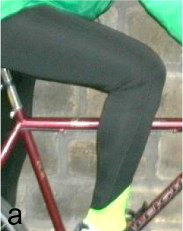
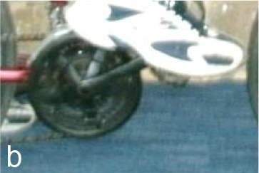
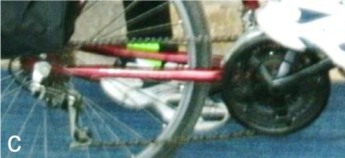
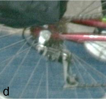


Figure 4.17Graphic Explaining the System Elements of the Bicycle Drive System. (a) Power Source, Cyclist’s Legs. (b) Crank Sprocket and Pedal. (c) Chain Drive Element. (d) Rear Drive sprocket. (e) Tires. (f) Bicycle Frame.
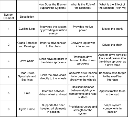
4.4.2.5.2.3 Step 3: Label and understand the impact of each step or element
This step is often best achieved by creating a chart, as shown in Figure 4.18, that categorizes the responses according to each feature of the system. It is also useful at this stage to number the system elements for use later in the synthesis.
The visuals in Figure 4.17 and the composite chart shown in Figure 4.18 will help the team to consolidate and explore the results of the first and second phases. As with any design, the design team must ensure that they have captured all the key components and that they have thoroughly understood the problem and the system.
The issues now facing a team and which must be addressed are as follows:
• What is the relationship between the components of the system?
• What are the influences or relationships between the components?
• What are the rules or laws that govern the link between the components? These are often scientific or mathematical in nature.
The pictorial visualization of each system component in Figure 4.17 allows the team to see the element and where it is placed in the system. It then becomes easier to see the relationship between the components.
Restate the Goal. It is useful to have the goal in sight as, say, a banner, to keep reminding the team of the goal:
How can we efficiently direct available rider energy to the road wheels of the bicycle?
Each component should now be visited by turn. The team asks the question:
What does this component do that affects the goal?
• Cyclist’s legs: produce power
• Crank sprocket and pedals: transfer power to the drive chain
• Drive chain: transfers drive force to the rear sprocket
• Rear driven sprockets: transfer drive torque to the tires
• Tires: transfer tractive force to the road surface
• Cycle frame: Holds in position all the system components
A second question should now be asked:
What does each component do that affects the goal of directing available rider energy to the road wheels of the bicycle?
For example, what do the rider’s legs do that affects the goal?
• Provide motive power
• Move the crank in a cyclic motion by pressing on the pedals
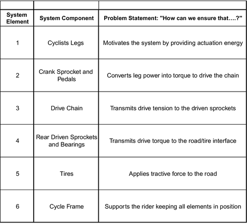
4.4.2.5.2.4 Step 4: State the links of the components to the goal
Using the data derived in step 3, the team must now examine the relationship between each component and the goal. Taking each component by turn, the question to be asked should take the following form:
How can we ensure that this component contributes to the final goal?
In particular, the question should commence thus:
How can we make sure that…
For instance, the question applied to Component 1 should read “How can we ensure that the cyclist’s legs provide........?”
The answers to these questions become problem statements from which the best statement will be selected for each system component.
Example: This phase requires the graphic in Figure 4.7 to be available to the team as they work through each system component asking the question “How can we make sure that…?” This will generate problem statements for each of the system components, as shown in Figure 4.19.
4.4.2.5.2.5 Step 5: Construct a rating table Comparing problem statements with feasibility
The next phase is to practically examine each system element so that the design effort may be focused toward the most feasible aspect of the system in order to achieve the goal. A rating table should now be constructed with all the problem statements listed and compared on the basis of the rating criteria. Typical rating criteria are listed here, and a typical rating table is shown in Figure 4.20.
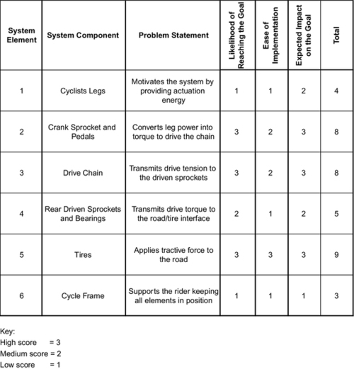
• The likelihood of reaching the goal
• Ease of implementation
• Expected impact on the goal
Care has to be taken when allocating scores as it can be very subjective. A more accurate score allocation can be achieved when the team members agree on a particular score. This brings all their collective experience and vision to the exercise, thus avoiding the possibility of a subconsciously biased view of an individual member.
4.4.2.5.2.6 Step 6: Select the most promising problem statements
The rating table shows that work applied to Component 5, the tire/road interface, seems to be the most promising system component on which to work. Component 2, Crank sprocket, and Component 3, drive chain, also score highly and should also be included for further consideration. Some caution should also be exercised as a high-scoring system component may not fit with the design strategy. For example, the design team may be specialists in chain drive systems, so it would be unproductive if they attempted to redesign the cycle frame. Furthermore, it is important to realize that this method may still be subject to the leanings of the design team even though the complexity of the process builds in natural safeguards.
The team may naturally concentrate on the high-scoring components, but consideration should be given to the low-scoring elements, even if it is to eliminate them. Component 1, the cyclist’s legs, represents the level of fitness and strength of the rider. At the beginning of the exercise, rider fitness was assumed to be at a particular level that could not be changed and was, therefore, outside the scope of influence of the exercise. Similarly, Component 6, the cycle frame, received a low score but it was also assumed to have a low impact on the end goal.
Scrutiny of the rating table in this way focuses the attention of the design team on the most promising development avenues.
4.5 Classic Brainstorming
Brainstorming has become one of the most popular forms of idea generation, probably because it is so easy and enjoyable to apply. Brainstorming is practically without rules, but it does have one rule that promotes free thinking and that is as follows:
No matter how crazy an idea it must not be ridiculed.
Participants can, therefore, give free rein to their imagination. If an idea is completely impractical, it may open up another avenue of thought for someone else in the group. Brainstorming brings several major advantages to the solution generation process. These are listed as follows:
• Pools the knowledge of several people to solve a problem
• Helps to eliminate mental blocks
• Restrains people from being critical
• Allows team members the freedom to think without constraints
• Expands effective participation for the team and other externals
• Avoids discussions that are not focused on the task at hand
4.5.1 Definition
This tool allows team members to pool their knowledge and creativity in an open and uncritical environment. Brainstorming encourages “open” thinking by
• creating a host of solutions that the team members can build upon
• involving all the team members
• giving equal value to every idea
• allowing each person to be creative while focusing on the team's common purpose
4.5.2 Step 1: Identify the appropriate team
For a brainstorming session to reach its full potential, the team leader should prepare for the session in advance as follows:
• Clarify the topic by using the Heuristic Redefinition or some other tool that simplifies the best route toward the supposed solution.
• Assemble a team whose expertise is based on the problem to be solved. There should be team members who have expertise in the most likely disciplines required, but the team should also include members from a range of diverse backgrounds. These members will often provide “out of the box” ideas.
• Try to map out the various directions so that he can coach the participants if some key avenues have been missed.
4.5.2.1 Bed lifting device example
Overview: A bed lifting device is to be placed in a domestic environment. The bed should lift to the ceiling during the day converting a bedroom into a living room and lower to the floor during the evening, thus converting the living room into a bedroom. The method of actuating (lifting/lowering) the bed is required.
Requirements
• silent
• safe
• easy to operate
• rise when required, into a ceiling cavity
• lower to the floor when required
The design solution required should be defined as follows: “Determine a means of elevating to the ceiling and lowering to the floor a fully made a bed of 300 kg. And actuation, application and guidance system should be incorporated.”
It is the task of the team leader to select a mix of employees, including technical experts, manufacturing personnel, marketing personnel, and others who may possess insight into the project and who may not be constrained by professional discipline.
4.5.3 Step 2: Convene the team and clarify the topic and ground rules
When the team meets for the first time, the team leader should exercise a loose control in briefing the team regarding their conduct and goal in terms of the following:
• Identifying and defining the focus topic
• Clarifying the meaning of descriptive words
• Reviewing the ground rules for participating in a brainstorming session. The ground rules are as follows:
1. Ground rule: Do not criticize or judge the quality of any idea. The purpose of the session is to generate rather than evaluate ideas. This posture ensures a good flow of ideas and freedom of thought. It also prevents long-winded discussions.
2. Ground rule: Combine the proposed solutions of team members to create new solutions.
3. Ground rule: Allow your imagination to break free from constraints. What may seem a crazy solution may set another team member along a different path toward a winning solution.
4. Ground rule: Give the team freedom to produce as many ideas as possible. The team should focus on the quantity of ideas rather than the quality. Quick snappy ideas without the encumbrance of explanations stimulate spontaneous thoughts prompt more unusual solutions from team members.
The brainstorming process is intended to be a fun and constructive experience for the whole team. During the process, each individual tem member should do the following:
• Engage himself/herself without reservation
• Not judge suggested solutions
• Look for positive elements in solutions suggested by team mates
• Be courageous
• Be carried away spontaneously
• Draw/sketch proposed solutions whenever possible
4.5.4 Step 3: Generate ideas
A typical brainstorming session should commence with several solutions being suggested. The intensity should build to a peak and then reduce to a pause in the solution flow. This is the first “dead point” where the team members need time to think.
After a short period of time, the flow of solutions should “self-start.” This does not always happen, in which case the team leader may be required to “jump start” the session using several techniques. One method would be to review the list of solutions and to request the group to expand on one or more of the interesting ideas.
The second phase usually reveals a small number of ideas. Since most of the more obvious solutions have been put forward in the first phase, the second phase reveals the more creative solutions. The second phase will also end in a dead point.
Sometimes it is useful to extend the session to a third and perhaps a fourth phase, each phase gradually progressing toward a more useful conceptual design. Figure 4.21 illustrates the phases of a brainstorming session.
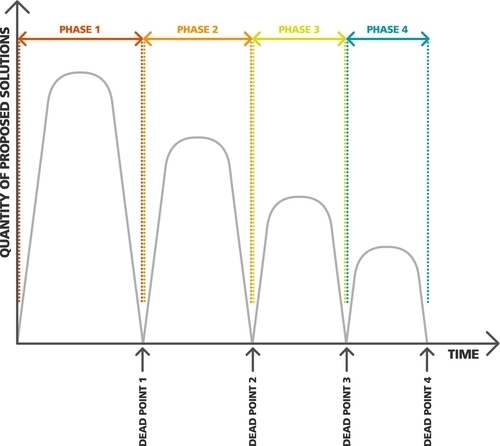
4.5.4.1 Example: bed lifting device
The team leader sets the scene by explaining the ground rules and the requirements of the device as follows:
Overview: A bed lifting device is to be fitted in a domestic environment. Methods of lifting and lowering the bed are required.
Requirements: The bed lifting system must
• Lift into the ceiling cavity, under control
• Lower to the floor, under control
• Be easy to operate by one person
• Be safe to use
• Be low cost
The problem statement is “It is required that a means of elevating to the ceiling and lowering to the floor a fully made up bed of approximately 300 kg. The solution also requires a guidance system.”
The definition and requirements have been deliberately left vague (open-ended) to avoid directing the team in a particular direction.
During the three sessions, the team generated the following solutions:
4.5.4.2 Phase 1-generated solutions
1. Apply lift cables from all four corners of the bed
2. Lift using a hydraulic ram from underneath the bed
3. Apply a gas bag underneath the bed
4. Apply a tractor beam (as used in Star Trek)
5. Apply screw jacks at each corner
6. For guidance, use rollers on a track
7. For guidance, use slides fixed to the wall
8. Use a counterbalance system enabling hand lifting
9. Use a lever mechanism to provide lift
10. Apply an electrically powered drive
Phase 1-generated solutions are usually adventurous and risky but, as can be seen here, many are impractical.
4.5.4.3 Phase 2-generated solutions
1. Treat the bed as a cantilever beam with the cantilever base at the wall
2. Apply rollers in a vertical channel at the base of the cantilever
3. Apply pneumatic rams to lift and lower the bed
4. Apply electric linear actuators
5. Apply a cable lift with a wind-up pulley-and-motor system
Phase 2-generated solutions are much more practical and begin to move away from conceptual solutions to more practical and achievable solutions.
4.5.4.4 Phase 3-generated solutions
1. Apply a roller chain lift with sprockets
2. Create the same lift from both sides of the bed using a pulley at each end of a shaft. The shaft is keyed to the pulleys so that they rotate at the same pace
3. Actuate the system using an electric motor with reduction box
4. Wind up the cable using a helix-grooved wind-up pulley
5. Reduce motor speed to an appropriate pace using a worm-wheel reduction box.
Phase 1-generated solutions show the list of solutions that emerged during the first phase of the brainstorming session. There were a large number of solutions contributed, several of which were not practical, but as the session progressed, the solutions became more usable.
In order to kick-start the next phase in a practical direction, the team leader asked the group to expand on the roller track system (from solution 6). Phase 2 solutions show that the team’s response was more practical and usable.
At the second dead point, the solutions became more technical as the team began to consider how the roller-and-channel system could be applied. The solutions in this phase also included a guidance system.
In order to start off the team contributions, the team leader then asked the team to expand on and incorporate solutions 1, 4, and 5. Phase 3 solutions show that the team’s response was very practical and came very close to the final solution.
Solutions generated during the third phase tended toward practical solutions, using known technology. The team leader decided that the appropriate direction had been isolated and now required specific design work.
Before the design work commenced, the solution set was reviewed by a nonattendee who dispassionately considered the solutions to
• Check the validity of the design route
• Ensure avenues had not been missed
4.5.5 Step 4: Clarify ideas and conclude the session
The list of brainstorming solutions should now be reviewed to check the design direction. This review should not be done during the session but later, by someone who was not at the session. The review should also clarify the next actions and the method of reporting the review to the team. This could be formal or informal, but it is necessary to focus the team on the next design phase.
The review for the bed-lift example made the following suggestions for the next design phase:
• Cantilever the bed from a structure incorporating rollers and channels
• Apply an electric motor/reduction drive system
• Develop a cable/pulley lift system alongside a chain/sprocket lift system
Efficiencies and costs of the chain lift and cable lift would then be compared.
4.6 Brain Writing 6-3-5
The previous method of generating ideas, brainstorming, is a highly verbal process allowing a group of members to share their ideas. Brain writing also allows sharing of ideas, but the team members have to write their solutions down on paper. The most popular version of this technique is Brain writing 6-3-5: this has six people in a group, three ideas for each round, and 5 min of idea generation for each round. It has distinct advantages in situations where there may be dominant group members or, conversely, members who have little confidence in a group.
There are additional advantages to brain writing, which at first may not seem obvious. They are as follows:
• Participation number in brain writing is unlimited. You need to just add another group of six
• Participants can think in more depth without distraction of discussion
• There is no criticism of ideas because there is no discussion
• No one person can dominate the discussion
• Lower-ranking participants may share their ideas more freely
• Shy people may feel more encouraged to participate
The disadvantages, however, are as follows:
• There is no spontaneity
• Crazy ideas are not immediately usable to create alternative trains of thought
• There is no team leader to guide the discussion
• Clarification of solutions is not immediate
4.7 Imaginary Brainstorming
This is a variation on Classic Brainstorming, where the introduction of a hoax element of the solution requirements tends to shift a person's thinking in a different direction.
The hoax involves replacing one element of a problem by a completely new element. The hoax change may be any aspect of the session. Even the wearing of underpants on the outside or pretending to snowboard in the office may be the change required.
The hoax changes the problem to something strange though it is still strongly related to the original problem. The effect on a group of members when they are solving the problem out of context is that it directs thoughts in new directions where old perceptions are put aside.
4.7.1 Tool overview
The start of an imaginary brainstorming process usually involves a classic brainstorming session where initial possible solutions are generated, listed, and clarified to the team members. The next step is to change one of the elements so that new ideas can be generated.
Once these essential problem elements have been listed, one of the elements may be changed to generate new ideas.
4.7.2 Example: mini cement mixer
The design problem given to a group of design students was to “design a mini cement mixer to mix 10 kg of aggregate.”
Key elements were defined as follows:
• Mixing a loose dry substance of 10 kg
• Mini size cement mixer
The team were concentrating on the word “Cement,” which led them down certain design paths. In order to get the team to consider alternatives, the word “cement” was changed to “Animal Feed.” This changed the team’s perspective and allowed them to create a nonpowered drum type, pull-along mixing device.
4.8 Word-Picture Associations and Analogies
An expert in a particular field tends to apply techniques he has applied previously. It is safe but perhaps unimaginative. When a new person enters the team he/she will have a different perspective simply because he/she is not “hide bound” by current or past methods. New technologies or new materials may be introduced that the “old” team have not considered.
A forward-thinking design team may realize that a fresh injection of ideas is required. Without the introduction of a “new” person, the same effect can be achieved by using associations.
Associations are really stirrings of memory that make mental connections to another place or time. A particular song may trigger the memory of a girlfriend/boyfriend or the smell of freshly baked bread may stir memories of a visit to a Paris boulangerie.
Analogies are a more direct comparison of a system or device.
Perhaps the best known analogy is that observed by the Swiss inventor George De Mestral who investigated how burdock burs stuck to his trousers after a country walk. Investigation using a microscope showed that each bur possessed hundreds of “hooks” that caught on to anything with a loop, such as clothing or animal fur. These direct analogies led De Mestral to develop a new type of fastener, Velcro. A microscopic image of Velcro can be seen in Plate 4.1.

Plate 4.1Microscopic View of “Velcro” [3].
Another example is provided by the designer RJ Mitchell, who designed the Spitfire and the Schneider Trophy aircraft. In the 1920s and early 1930s, they were cutting-edge float plane designs with a single wing, when most aircraft at the time were biplanes. Mitchell analyzed the flight and structure of birds’ wings in order to formulate the streamlined nature of his aircraft and the design of the wings. The Supermarine S6, winner of the 1929 Trophy, can be seen in Plate 4.2.
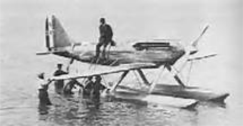
Plate 4.2Supermarine S6, Schneider Trophy Winner [3].
RJ Mitchell famously went on to design the Supermarine Spitfire, the WWII British fighter plane. Plate 4.3 shows a Spitfire. Design similarities between the Spitfire and the Supermarine S6 can be clearly seen.

Plate 4.3Supermarine Spitfire Designed by RJ Mitchell [3].
4.9 Methods of Generating Associations and Analogies
4.9.1 Random words
There are several methods of generating associations and analogies that can influence a design. One method is to introduce random words into a problem. The association and probable analogies generated allow a team to examine the unique characteristics that the word might provide to the problem. During the process, the team should be asking questions such as:
• What associations are brought to mind?
• What are the connections that the random word generates?
• What comparisons does the random word stimulate?
4.9.2 Pictures
The human condition uses visual aids almost 80% of the time. It makes sense, therefore, to use visual aids (pictures/diagrams) to stimulate associations and other analogies. The team members may review a random picture (magazine article, technical brochure, etc.) in order to stimulate associations that might apply to the design problem.
In this way, the use of visuals creates thought processes that allow individuals to replace insufficient or incomplete information in their imaginations with an image.
For example, during the design of a sports car, the specification requires wide tires with alloy wheels, but the memory carries only a skeletal outline. The insertion of a picture of wide tires with alloy wheels serves to indicate a more complete design than that in the imagination of the team members.
4.9.3 Biotechniques (biomechanics)
This is the process where a naturally occurring device or structure is analyzed to understand its function. George De Mestral did exactly this when inventing “Velcro.” The modern aircraft wing is basically a cantilever beam. Cantilevers abound in nature in the form of tree branches. Naturally formed arches, perhaps at the entrance to caves, are naturally occurring lintels, which are used extensively in buildings in the form of support beams above doorways or windows.
This technique makes use of the enormous number of solutions nature has developed. The analysis of natural phenomena is always an excellent beginning for idea generation.
4.9.3.1 Biotechnique tools: overview
The use of an analogy or an association is a fairly high-level method of solution generation and requires an initial input of possible solutions derived from Classic Brainstorming or Brain Writing.
The team leader then has a choice as to whether to use random words, pictures, or biotechniques/biomechanics as the primary feed to generate associations or analogies. Depending on the problem, a single element or a combination of elements may be used. The team leader guides the team through the generation of associations or analogies. These solutions are then linked to the solving of the problem.
4.9.3.2 Example: bed lifting device
A team has been assembled to explore solutions to the problem: “It is required that a means of elevating to the ceiling and lowering to the floor a fully made up bed of approximately 300 kg. The solution also requires a guidance system.”
During the initial phase 1 brainstorming session, the team generated the following solutions:
Phase 1-Generated Solutions
6. Apply lift cables from all four corners of the bed
7. Lift using a hydraulic ram from underneath the bed
8. Apply a gas bag underneath the bed
9. Apply a tractor beam (as used in Star Trek)
10. Apply screw jacks at each corner
11. For guidance, use rollers on a track
12. For guidance, use slides to the wall
13. Have a counterbalance system for hand lifting
14. Use a lever mechanism to provide lift
15. Apply a four-bar link system
It is now necessary for the team to define the technique to use: word association, picture association, or biotechniques/biomechanics.
4.9.3.3 Word associations
The team leader would need to plan ahead so that he would have collections of words that are independent from the problem. The words could be derived from several sources, such as a thesaurus, dictionary, newspaper, magazine, or a mail order catalog.
The choice of words should be random, but general themes could be applied so that for technical problems, such as the design of a vehicle power plant, the random words could relate generally to, say, aircraft or other similar material objects.
4.9.3.4 Picture associations
A randomly chosen set of pictures can be shown to the team, perhaps projected onto a screen. The picture should portray a variety of situations and activities that are unrelated to the problem. In the case of a bed lifting device, pictures could be shown of elevated buildings or escalators, or perhaps scissor lifts for cargo.
Pictures can be sourced from almost anywhere. Popular sources are as follows: magazines, books, travel magazines, industry magazines, and the Internet. It is often difficult to judge the response of the team, but the team leader should endeavor to select pictures that may lead the team to give an upbeat and positive response.
4.9.3.5 Biotechniques (biomechanics)
The application of biotechniques is perhaps the most difficult as the team will need to familiarize itself with models, books, specimens, and other research materials. In order to do this and to carry out appropriate research, the team would need to first analyze the actual design problem. The research will remove the randomness of the activity and help in a positive fashion as the team will become better informed.
4.9.3.6 Stimulating the team
Whichever element is selected (word, picture, or biomechanics/biotechnique), the team leader should stimulate the team by asking appropriate questions while it is considering one of the elements. Difficult questions with which to stimulate the team can be seen in Figure 4.22.
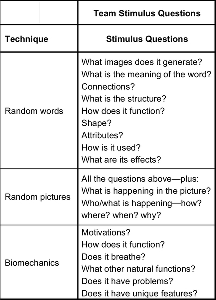
For the clockwork mechanism shown in plate 4.4, the team worked through the stimulus questions outlined in Figure 4.22 and derived 23 associations, some of them, however, were overlapping associations. The team leader then sifted through the results, eventually creating three categories as follows:
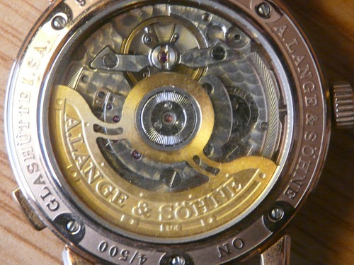
Plate 4.4Picture of a Clockwork Mechanism [3].
Attributes
• Controlled mechanism
• Controlled spring energy
• Precision
• Wind-up and release system
• Instrumentation
• Movement of analog fingers for humans to read the time
Method of Operation
• Small gears
• Shafts rotate on bearings
• Uses spring energy
Uses
• Telling the time
• Enabling the calculation of longitude
• Timing of races
• Moving with precision
4.9.3.7 Apply the generated ideas to the problem
Guided by the team leader, the team now considered each idea by turn, creating associations and analogies linked to the bed lifting device. The team leader then created a chart that listed the new ideas next to the associative trigger. These associations and analogies can be seen in Figure 4.21.
After considering the first trigger the team moves on to the next trigger creating further associations and analogies. The process continues until a sufficient number of ideas have been generated (Figure 4.23).
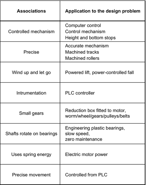
4.10 TILMAG
The methods already discussed are extremely prolific in their idea generation; however, for really tough and stubborn problems for which there is a scarcity of ideas, the structured TILMAG approach is most helpful.
TILMAG is a solution generation technique created by Dr. Helmut Schlicksupp. The word TILMAG is an acronym for several German words, which loosely translated means “the transformation of ideal solution elements in an association matrix.”
4.10.1 Technique operation
The general operation of this technique is with a matrix that allows associations to be made; pairs of possible solutions are combined so that they can be explored, often providing unusual breakthrough solutions.
The team first generates several desirable solutions using a basic technique, such as brainstorming. The solution is then inserted into the matrix for evaluation. A step-by-step procedure is provided here.
Step 1. Generate solutions using a basic technique such as brainstorming
Step 2. Define ideal solutions
Step 3. Construct a TILMAG Matrix incorporating the ideal solutions
Step 4. Consider each empty cell by turn, making associations by pairing ideal solutions and the associations in the matrix boxes
Step 5. Combine the new associations derived in step 4 with the ideal solutions defined in step 2
4.10.2 TILMAG matrix
The basic TILMAG Matrix can be seen in Figure 4.24. It shows how seemingly different solutions can be matched with other solutions. In practice, this combination technique often leads to new and useful solutions.
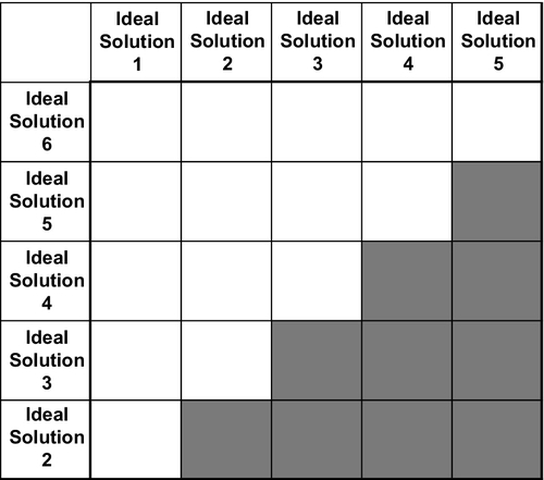
4.10.3 Example: bed lifting device
Consider the bed lifting device, which was first considered as an example of brainstorming. The problem definition is as follows:
It is required that a means of elevating to the ceiling and lowering to the floor a fully made up bed of approximately 300 kg. The solution also requires a guidance system.
4.10.4 TILMAG phase 1
The first phase in any complex solution generation method is to revert to a basic solution generation technique such as brainstorming. The team-generated initial solutions from the “Phase 1” brainstorming session are listed below:
Phase 1-Generated Solutions for the Bed Lifting Device
1. Apply lift cables from all four corners of the bed
2. Lift using a hydraulic ram from underneath the bed
3. Apply a gas bag underneath the bed
4. Apply a tractor beam (as used in Star Trek)
5. Apply screw jacks at each corner
6. For guidance, use rollers on a track
7. For guidance, use slides fixed to the wall
8. Use a counterbalance system enabling hand lifting
9. Use a lever mechanism to provide lift
10. Apply an electrically powered drive
4.10.5 TILMAG phase 2
Sometimes these generated solutions may require some refinement. The most promising “ideal solutions” were selected by the team for insertion into the TILMAG Matrix. They are listed here:
1. Apply lift cables from all four corners of the bed
5. Apply screw jacks at each corner
6. For guidance, use rollers on a track
8. Use a counterbalance system enabling hand lifting
9. Use a lever mechanism to provide lift
10. Apply an electrically powered drive
4.10.6 TILMAG phase 3
After having isolated the most promising “ideal solutions,” insert them into the TILMAG Matrix as shown in Figure 4.25.
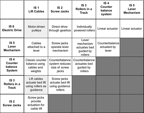
4.10.7 TILMAG phase 4
Consider each empty cell by turn, making associations by pairing ideal solutions and the associations in the matrix boxes. As can be seen in Figure 4.25, the ideal solutions have been combined in such a way as to create new solutions.
4.10.8 TILMAG phase 5
Combine the new associations derived in step 4 with the ideal solutions defined in step 2.
The team can now use its experience and expertise to consider the solution displayed in each box. The scrutiny of each solution may involve elements such as
• cost
• feasibility
• fitness for purpose
• ease of manufacture
• noise
• maintenance
• power source
The team may also consider combining boxes. In practice, the bed-lift device employed a combination of the shaded boxes in Figure 4.25. The system employed motor-driven pulleys, which wound lift cables, thus actuating the lift of the bed using rollers running on a track for guidance. This was the most cost-effective and practical method.
4.11 The Morphological Box
The application of morphology to a problem is essentially trying to change current parameters into something else. The morphological box is useful when considering whole systems rather than individual elements. It is important, therefore, that the team or, indeed, an individual designer needs to understand the whole system and its fundamental problem structure.
The first stage of the process is to list all the parameters that can be included or might affect the outcome of the design. This could be motor type, guidance system, actuation method, etc. For each parameter, multiple options are defined and listed within the morphological box. Once the tool has been created, it is a fairly easy exercise to combine the various options from other parameters. The result of the exercise is a larger number of alternative solutions.
4.11.1 Tool overview
The first step in the process is to identify and define the characteristics that are essential to a solution.
In a technical example, a wheelbarrow could be the focus of attention; the parameters would be as follows:
• Can carry a weight of 50 kg
• Can carry loads of any shape
• Can be operated by one person
• Can be operated over rough terrain
• Can be used outdoors
In setting up the morphological box as shown in Figure 4.26, it can be seen that by combining parameters by joining options with lines, several different and unique solutions can quickly be shown. A more complex morphological box will naturally lead to many more options.

Figure 4.26Morphological Box for Wheelbarrow Alternatives [2].
This is an excellent method to view the whole system and can be used by a team or by an individual designer.
Perhaps the most difficult time for a designer is right at the beginning of the project when he/she is faced with a blank sheet of paper. In devising the system, the designer will, in his mind's eye, go over the various parameters and review the options for each parameter. The morphological box represents this process as a visual aid, which can be added to and used many times for other similar projects.
Figure 4.27 shows the morphological box devised for the bed lifting device. The left-hand column shows all the important parameters such as the actuation, the control systems, and the lift method. The columns to the right represent the options available for each parameter. For instance, the actuator for the system could be an electric motor, pneumatics, or hydraulics. It is now a fairly simple task for the designer to select the options and merely join them with straight lines. This method can quickly simplify the process of devising a whole system.
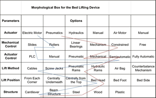
Figure 4.27Morphological Box for the Bed Lifting Device [2].
The morphological box shown in Figure 4.27 offers two alternatives.
The first method suggests that the bed lifting operation can be powered by an electric motor driven lifting rollers controlled by a Programmable Logic Controller (PLC). The control is deemed to be semiautomatic so that human input can at least start it on the lift cycle or descent cycle. The structure is made from steel and takes the form of a cantilever secured at the bed head end where lift cables are able to raise and lower the bed.
The second method is powered by pneumatics and is constrained to move using pneumatic brands with pneumatic control. The actuation is from the bed head because the structure is based on a cantilever manufactured from steel.
4.12 Design and Planning Methods
The practice of design is often viewed by nonpractitioners as an open-ended and largely artistic discipline. In fact, engineering design combines a creative aptitude with practical discipline and is often time-dependent so that designers are often working round the clock to meet tight deadlines. The achievement of good designs and their timely conclusion to projects is usually the result of good organization and scheduling.
To ensure that a design project is completed on time, the design manager must prepare a suitable plan, which must take account of such things as the creative process, team aptitude and experience, component selection, materials selection, detail design, and checking.
Two common techniques used in the project planning stage are
• Gantt charts
• Network planning charts (network analysis)
4.12.1 The Gantt chart (activity sequence chart)
This was the first formal method used to establish the start and finishing times for various phases of a product. It was devised by Henry L Gantt at the turn of the twentieth century.
A typical though fairly simplistic Gantt chart can be seen in Figure 4.28. Generally, the activities are displayed in a column on the left-hand side while a time scale is placed horizontally along the top of the chart. The activity column in Figure 4.28 shows a typical design process, which can be fairly detailed. The time scale is shown in weeks though any convenient time scale can be used depending on the project.

The strength of the Gantt chart lies in its simplicity. It can be understood at a glance without a great deal of training. Figure 4.28 shows the planned time allocated to each duty as a blue bar. As the project progresses, the actual time spent on each activity can be planned. This is shown as a red bar. This kind of chart is extremely useful for the project manager, because he can see exactly where time overruns and bottlenecks are occurring.
It should also be noted that some activities can be carried on simultaneously with other activities. For instance, the generation of solution possibilities can occur even while research into the brief is ongoing. These kinds of multiple activities are quite common in most projects.
The Gantt chart is a very useful project planning tool and can be as simplistic as that shown in Figure 4.28 or hold much more detail such as the example shown in Figure 4.29.
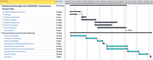
Figure 4.29Typical Microsoft Project Gantt Chart [4].
There are many excellent software packages that allow Gantt Charts to be easily contrived. Some offer only Gantt charts while others offer other planning tools such as network analysis and activity listings. The Gantt Chart shown in Figure 4.29 has been created in Microsoft Project.
4.12.2 Network planning (critical path analysis)
The Gantt Chart covers some useful aspects of project planning, but it does miss some vital project planning elements. The Network Planning technique lends itself to more complex activities and is often used on large projects as a single planning tool. Its main advantage is that it gives planners the opportunity to plan a “critical path” that allows for longer lead time items to be integrated into the program. Network planning, however, lacks the immediacy of a Gantt Chart and for this reason, it is commonly used alongside Gantt charts when large projects are being planned.
The main advantage of network planning is that activities can be allocated a length of time for completion. The supply of a critical component such as a screw compressor may take, say, 3 months from the order date. If the project is to be completed in 4 months, then this critical component will need to be ordered very early in the project time scale. Other activities may include chassis fabrication, which will take only 1 week. This is clearly not a critical length of time and the activity can be planned within the overall time plan for the part to be ready in time for the assembly of the compressor.
The various tasks within the project can therefore be classified into high-priority or low-priority activities, as shown here:
• Low-priority activities are those that can be inserted into the time scale flexibly without affecting the overall completion date
• High-priority activities, however, cannot be delayed without extending the project duration. High-priority activities are said to lie on a Critical Path.
A network analysis consists of two major building-block elements: Activities and Nodes (Completion of Activities). Examples of these are shown in Figure 4.30.
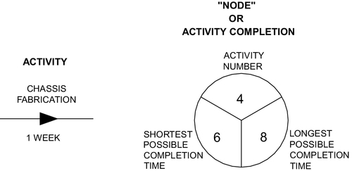
• Activities: They are denoted by straight lines complete with arrowheads. The description of the activity is usually placed above the line, with the activity time allowance placed below the line.
• Nodes: They are denoted by circles and include
• An activity number
• The earliest possible completion time
• The latest possible completion time.
In order to illustrate the way to construct a network diagram, let us analyze the simple task of making a mug of coffee. Figure 4.31 shows the list of activities required. On the network, activities 1, 2, 3, and 4 do not lie on the critical path and can take secondary routes from the starting point.
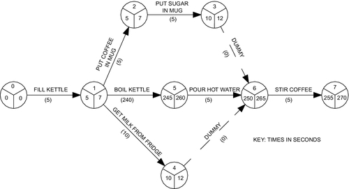
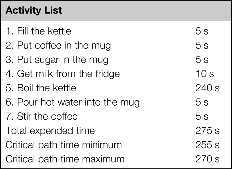
4.12.2.1 Time allocation
Time allocation is noted underneath the activity line. This is added at the node. Also at the node can be a time tolerance value. In node 1, the allocated time is 5 s but the time tolerance value is 7 s. Estimated tolerances such as this can be inserted into any node should the activity require it.
The left-hand quadrant of each node displays the shortest time and should continually add up to the shortest time as the diagram progresses from left to right. The right hand quadrant displays the longest time and should similarly add up to the longest estimates as the diagram progresses through the project.
4.12.2.2 Critical path
The critical path is the line that shows the earliest and latest completion times. The time allocation for the longest critical activities lies on this line. Activity 5 is allocated 240 s and is the longest of all the activities. Activity 6 is dependent on activity 5 and, therefore, has to follow it. Though activity 5 takes only 5 s, it lies on the critical path simply because it cannot be actioned until the kettle has boiled.
Several activities may converge on a single node. In this case, insert the longest time values. These nodes should normally lie on the critical path, but in complex networks, there may also be a minor critical path, which may possess convergent nodes. Purists may argue that there should be only one critical path, but some complex projects may demand several network routes.
The critical path can be recognized as the line that equals the earliest and latest completion times. The critical path from Figure 4.31 is as follows:
Critical path = 0-1-5-6-7.
The activities that lie on the critical path determine the value of the overall completion time and are high priority. Any delays in these activities will result in an extended project.
Activities 2, 3, and 4 do not lie on the critical path and are therefore not critical activities. They can be executed at any time during the period between activities 1 and 6 but must not take longer or they will lengthen the project time.
4.12.2.3 Dummy activities
Dummy activities show no process and have no time allocation. They facilitate the return of a low-priority activity to the critical path through a convergent node.
4.12.3 The complete planning exercise (PERT)
A technique that brings together all the planning activities associated with a project is known as PERT (Programme Evaluation and Review Technique).
PERT is a management method that analyzes the tasks involved in completing a given project. In particular, the method closely considers the time needed to complete each task, and identifies the minimum time needed to complete the total project.
PERT was developed for large complex projects where planning had to be simplified. PERT was originally developed for the U.S. Navy Special Projects Office in 1957 in support of the U.S. Navy's Polaris nuclear submarine project. PERT is a technique that uses events where other techniques use beginning and completion strategies and is often used in projects where time rather than cost is important. PERT is very useful in many diverse projects, but it is particularly advantageous when used to plan large-scale, one-time, complex, nonroutine projects. The technique was used to great success in the planning of the Grenoble Winter Olympics in 1968.
There are three main activities associated with PERT and they are listed as follows:
1. Complete a list of tasks and allocate a sequence number
2. Arrange the tasks in a network and define a critical path
3. Allocate an estimated time to each activity, thus creating a Gantt Chart
An example of PERT tasks can be seen in Figure 4.32.
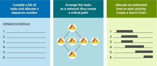
4.12.4 Case study: flywheel energy storage system
A design manager has created a design team that has been tasked to design a large flywheel energy storage system. Figure 4.33 shows the conceptual design of the flywheel energy storage system. The schematic shown is merely a concept and requires the design of the manufactured components and the specification and selection of bought-out components.

4.12.4.1 Complete a list of tasks and allocate a sequence number
This is perhaps the hardest part of the planning exercise, where the manager has to visualize the activities required to complete the project and list the tasks as closely as possible to the natural sequence of events. When he/she is satisfied with the list, the design manager can allocate personnel with appropriate expertise to each task. Figure 4.34 shows the task list for the flywheel design.
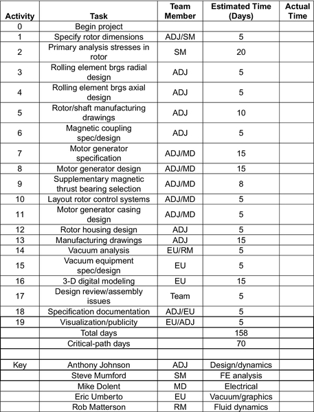
Figure 4.34Task List for the Flywheel Energy Storage Design [2].
4.12.4.2 Arrange the tasks in a network and define a critical path
Armed with the list of tasks, the design manager can now create a network analysis. This will show the critical time-dependent activities that have to be completed within the allocated time in order to keep the project on track. The network analysis for the flywheel energy storage device can be seen in Figure 4.35. It should be noted that several activities, such as 6, 14, and 15, do not take as long as those on the critical path, which is: 0-1-2-5-11-12-13-17-19. The critical path activities require full attention if the project is to meet the projected completion time of 70 days.
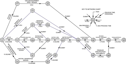
Figure 4.35The Network Diagram for the Flywheel Energy Storage Device Design [2].
4.12.4.3 Allocate an estimated time to each activity, thus creating a Gantt Chart
The main tools of the task list and the network analysis chart are now in place. The Gantt Chart (activity sequence chart) can now be assembled using the data from the network analysis and the task list. The Gantt Chart represents the whole project and allocates tasks to team members who have particular skills. The Gantt Chart fulfills other more subtle duties in that it allocates responsibility for a task completion to a particular team member.
The Gantt Chart for the flywheel storage device design can be seen in Figure 4.36.
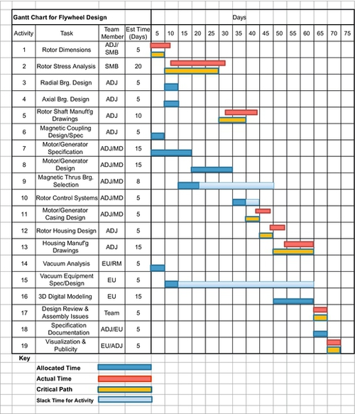
Figure 4.36Gantt Chart for the Design Process of the Flywheel Energy Storage Device [2].
The Gantt Chart allows a design manager to manage his team. Inevitably, a design team will be working on several projects at once, and personnel may be required on the critical elements of other projects as well. The PERT procedure and, in particular, the Gantt chart allow the design manager to move his staff between projects so that the critical path times can be met.