
The consumption of the H2 line is equal to 4568 kW.
The consumption of the O2 line is equal to 3285 kW.
b. Now we compare the three technologies in terms of cost and emission generation. In the table below, we see the cost of each technology considering not only the investment in the plant, but also the emission tax and the cost for the area that will be used. Biomass turns out to be the cheapest option.
| Cost (€) | CO2 (kg) | Area (m2) | Emission (€/kg) | Ground (€/m2) | Environmental Impact (€) | ||||
| Wind | 1300 | 0.5 | 0 | 524,555,513 | 201,752 | 0 | 0.04 | 25 | 524,563,583 |
| Solar | 1150 | 1 | 5 | 464,029,877 | 403,504 | 2,017,521 | 0.04 | 25 | 514,484,047 |
| Biomass | 1000 | 0 | 10 | 403,504,241 | 0 | 4,035,042 | 0.04 | 25 | 504,380,301 |

c. In order for wind to be the cheapest option, its cost must be lower than 1250 €/kW.
4.2.4 Thermochemical Cycles for Water Splitting
The energy for water splitting that can be provided as work, ΔG, becomes zero at 4000°C. Therefore at that temperature, only thermal energy would be necessary for that operation, reducing the yield loss due to the production of power. Note that it is infeasible from the practical point of view. In order to thermally split water, we should be able to work at 700–900°C, which can be achieved at nuclear reactors, for instance. To reach those temperatures, we can produce a series of chemical reactions whose global operation yields water splitting, recycling the other chemicals involved.
There are more than three hundred different cycles. To decide on a promising alternative, the characteristics of the cycle that must be considered are the number of reactions or steps; the number of elements involved; the cost and availability of chemicals; the types of materials needed for construction and processes; the corrosivity of the species involved; the safety, health, and environmental considerations of the chemicals and the operating conditions; the effect of temperature on costs; the maturity of the cycle; the thermal efficiency; the operating temperature; the similarity of reaction kinetics among the different stages (fast in general); the purification of the products; and the fact that ΔG must be zero or negative to reduce the energy requirements. We classify the cycles into four groups: halides, oxides, sulfur, and hybrids (Aporta et al. (2011)).
4.2.4.1 Family of the halides
The general chemical reaction is as follows:
Since the 1970s the Euratom initiative (Ispra, Italy) has studied different cycles. For instance, the one named Mark I uses mercury and bromide. The reactions and their respective temperatures can be found below. The major risks are in the operations with Hg and Br, which are health hazards:

Another cycle that avoided the use of such dangerous chemicals received the name Mark 9, and was also proposed by Euratom. The cycle is as follows:

4.2.4.2 Family of the oxides
The general reaction is as follows:
where the metal (Me) can be Mn, Fe, or Co.
4.2.4.3 Family of sulfur
In this family, we highlight two cycles. The first one is the iodine–sulfur cycle, given by the following reactions:

The second cycle is the sulfate one, given by the following set of reactions:

4.2.4.4 Hybrid cycles
In parallel to the efforts presented above, the Westinghouse Corporation proposed a hybrid cycle that combined an electrochemical stage (taking place at low temperature), and another thermal one. The optimum efficiency, 40%, is obtained for 65% sulfuric acid. However, it can be increased up to 46% if the electrolysis takes place in a series of stages.

4.2.5 Sodium Chloride Industry
Sodium chloride (NaCl) is the most abundant salt in seawater, and is the main raw material for sodium and chloride chemical production Bertram (1993). The separation of NaCl had already been done in ancient times by solar evaporation of water. An evolution of this method, adding green dyes (solivap green), is still in operation today. Thus water is stored in low, deep pools exposed to high solar intensity. As solar and wind energy evaporates water from the pools, different precipitates remain in solution. In the beginning, CaCO3 and Fe(OH)3 precipitate. Later, as the density increases, other salts precipitate. Table 4.6 shows the salt and purity obtained.
Table 4.6
Salts Precipitated by Solar Evaporation
| Density (kg/L) | Species Precipitated | Use |
| 1.21 | CaSO4·H2O | |
| 1.21–1.23 | NaCl 96–98% | Food industry |
| 1.23–1.25 | NaCl 92–95% | Chemical industry |
| 1.25–1.29 | NaCl 92% | Brine |
Following this procedure, we can recover up to two-thirds of the NaCl. In the mother liquor there are still NaCl (up to 35%), MgSO4, MgCl2, KCl, and NaBr. Thus, the procedure can continue. Therefore, we can obtain MgSO4 and KCl with a low level of purity. We can treat the mother liquor with CaCO3 and/or MgCO3 to produce Mg(OH)2. Next, by bubbling Cl2 gas, Br2 is generated. There are two processes to carry out the production of Br2 from the mother liquor. The first one (just described) is known as the Kubiersky method. The second is Dow’s method. It is an electrolytic-based method to extract bromine from brine. It was patented in 1891. The brine is treated with sulfuric acid and bleaches to produce bromine by oxidation of bromide, which remains dissolved in the brine. Next, the solution is dripped onto burlap, and water is blown through it so that the bromine volatilizes. Bromine is thus trapped with iron turnings to produce a solution of ferric bromide. By using more iron metal, the ferric bromide is transformed into ferrous bromide. Thus free bromine can be obtained by thermal decomposition of the last species.
Various salts can be obtained from seawater, but the following sections focus on the use of NaCl as a raw material for Na2CO3. Until the 1800s it was believed that K2CO3 and Na2CO3 were the same species since they were both alkalis that were obtained by calcinations and lixiviation of plants. The Na2CO3, also known as washing soda, or soda ash, is of particular interest in the production of soaps, glasses, as well as paper, phosphates, oxalates, and borax. The two processes that have been used industrially are Leblanc’s process and Solvay’s process Solvay Alkali GmbH (1998), Rauh (1993).
4.2.5.1 Production and use of sodium carbonate (Na2CO3)
4.2.5.1.1 Production via Leblanc’s process
Historical perspective: In 1775 the French Academy of Sciences offered an award of 2400 Livres for a method to produce soda ash from sea salt. Nicolas Leblanc (1742–1806), chemist and physician to Louis Phillip II, Duke of Orléans, proposed a method and obtained the patent in 1791. That same year he built a plant at Saint–Denis (Paris) worth 200,000 Louises to produce 320 tons of product a year. The facility only operated until the Duke’s death by guillotine in 1793. That forced him to open the patent and he was denied the award. Napoleon returned the plant to Leblanc in 1801, but unable to upgrade it to compete with the new processes, he committed suicide in 1806. In 1818 the first plant was built in Germany, and later, in 1823, another was built in England.
Process: The process follows the chemical reactions below.
Fig. 4.24 shows the scheme of the process. NaCl is mixed with sulfuric acid and then the solution is heated. The HCl is vented to the atmosphere. Next, the mass is exposed to direct flame to remove the remaining chloride. Coal and calcium carbonate are then used in a proportion of 2:2:1 for the salt, the carbonate, and the coal, respectively. The mixture is heated up to 1000°C in a furnace. The black ash produced needs to be lixiviated to avoid oxidation to sulfate. For that it is covered with water. The lixiviation takes place in stages. The final liquor is processed to precipitate the carbonate after cooling down the mixture. Some of the drawbacks of the process are that all the reactions occur in solid phase, being slow, and consume large amounts of energy. Furthermore, the process presents several environmental concerns.

In those early days the HCl was useless and was vented. Furthermore, smelly solid CaS was also produced, and had no further value either. When piled up, it produced hydrogen sulfide. Because of these emissions, in 1839 the facilities received a formal complaint due to the effect of the process on the surroundings. As a result, the British Parliament in 1863 passed the first of several Alkali Acts, regarded as the first modern air pollution legislation. In this particular case, the Act did not allow venting of more than 5% of the HCl produced in alkali plants. Absorption beds using charcoal were installed in the plants and absorbed in water, producing hydrochloric acid. Later, the CaS was used to recover the S and produce sulfuric acid, and the HCl was used to obtain Cl2 via oxidation.
Example 4.7
We would like to produce 10 t/day of Na2CO3 using the Leblanc process, given by the following reactions:

Compute the amount of raw material and byproducts, assume that the conversion of the reactions is 100%, and the volume of commercial sulfuric acid, considering that the concentration is 60°Be.
Solution
°Be is a density-based measurement. For liquids denser than water
10°Be is the density of a 10% solution of NaCl in water and
0°Be is the density of distilled water at 15.6°C.
For liquids less dense than water:
0°Be is the density value of a solution of 1 g of NaCl and 9 g of water;
Since sulfuric acid is denser than water, and °Be=60, we use the first of the two equations to compute the relative density to water, with a result of 1.706. Water density at 15.6 is 0.999007 g/cm3 based on tables. Thus the actual density is 1.7042 g/cm3. Using tables for sulfuric acid (see Perry and Green 1997), we can interpolate the weight percentage for the temperature of 15.6°C (Table 4E7.1).
Table 4E7.1
Sulfuric Acid Densities (g/cm3)
| % peso | 15°C | 20°C | 15.6°C |
| 77 | 1.6976 | 1.6927 | 1.6970 |
| 78 | 1.7093 | 1.7043 | 1.7087 |

Thus, for a density of 1.7042 g/cm3, we interpolate a mass fraction of 77.62%. From the mechanisms we compute a global reaction for the entire process as follows:
Based on the stoichiometry of the reaction, and using a day as the basis for the calculations, the moles of sodium carbonate needed in the process are computed as follows:
The need for raw materials is as follows:

Thus, the commercial acid that we need is computed from the pure raw material as follows:

The products of the process are determined as follows:

4.2.5.1.2 Production via Solvay’s process (ammonia soda process)
Chemical history of the process
In 1811 the French physicist Augustin Fresnel discovered that sodium bicarbonate precipitates when carbon dioxide is bubbled through ammonia brine.
This reaction takes place in a series of reactions as follows:

Ammonia acts as a buffer for high pH, at which sodium bicarbonate is not soluble and precipitates. The bicarbonate is decomposed by heating, as given by the following reaction:
However, the reversibility of the reactions requires that one of the raw materials (NaCl or NH4HCO3) be fed in excess instead of in stoichiometric proportions. The cheapest one, the NaCl, is the one fed in excess. To recover the precipitated bicarbonate, the stream must be cooled down to 30°C so that it crystallizes.
From an industrial point of view, this process did not require sulfuric acid, which was in high demand back then, and the reactions took place in solution. However, the drawback of the process was the consumption of ammonia. Before the Haber–Bosch process, ammonia was produced as a byproduct in charcoal production or from manure decomposition. The high demand for ammonia, and thus its cost, made the process difficult to scale up. The recovery of ammonia within the process changed this aspect. In 1822 the recovery of ammonia was already known. Using a strong alkali, Ca(OH)2, the ammonium cation was transformed into ammonia that could be distilled. The Ca(OH)2 was internally produced using calcium carbonate, which decomposed into calcium oxide. Finally, CaO reacted with water to produce the calcium hydroxide.
Thus NH3 was recovered as follows:
The Solvay process can be summarized in the following global reaction:
Although some of the reactions had been known since 1811, there were problems in the process design. In 1861 the Belgian industrial chemist Ernest Solvay proposed the use of a 24 m tall absorption tower in which carbon dioxide was bubbled through a flow of ammonia containing brine. This unit incorporated an arrangement for cooling down the bicarbonate to separate it from the products. Finally, ammonia was also recovered as suggested by Augustin Fresnel. By 1864 Ernest and his brother Alfred had built a plant near Charleroi (because of the existing chemical industry in the region) to provide for coal and ammonia. The production capacity was 200–250 t/yr. By 1880 Solvay’s process, which was more environmentally friendly than Leblanc’s, completely displaced it.
Flowsheet
Fig. 4.25 shows the flowsheet for the production of sodium carbonate from NaCl, coal, and calcium carbonate as raw materials.

The solution feed is treated with Ca(OH)2 and Na2CO3 to eliminate the cations Mg2+ and Ca2+ in the form of Mg(OH)2 and CaCO3, since otherwise they would precipitate with CO2. Next, Tower T-01 is fed with a saturated solution of NaCl. This column receives the regenerated NH3 from T-05. The ammoniacal brine is diluted with the water that accompanies the ammonia. To reconcentrate the solution, it is fed to T-02, a packed bed of solid NaCl. The ammonia brine is then fed to Solvay Tower T-03, where it is put in countercurrent contact with the CO2 that rises across the tower. CO2 streams with different concentrations are fed at various levels. Concentrated CO2 from the decomposition of the sodium bicarbonate is fed into the bottoms of the columns. Diluted CO2 from the decomposition of calcium carbonate is fed above the cooling stage of the column (see Fig. 4.25). The gas with a small content of CO2 exits the tower from the top. Along the tower, the ammoniacal brine descends and is put into contact with gases with higher concentrations of CO2 so that an equilibrium among the species NaHCO3/NH4Cl/NaCl/NH4HCO3 is reached. The Solvay Tower uses double trays. Furthermore, in the lower part there is a bundle of cooling tubes for reducing the temperature to 30°C, allowing precipitation of the sodium bicarbonate and its separation. A suspension is obtained from the bottom of the tower.
The equilibrium of the species is studied using the Jaenecke diagram (see Fig. 4.26), which represents the pairs of species. From top to bottom the anions are represented (Cl− and HCO3−), and from left to right the cations (NH4+ and Na+). The feed to the column is at opposite vertexes, NaCl and NH4HCO3. The lever rule can be used to determine the feed composition as a function of the ratio between those two. The product, NaHCO3, is at the right bottom vertex. A line connecting this point to the feed point is extrapolated to the equilibrium lines. Next, this point is connected to the NaCl vertex. We draw a line parallel to this one by the feed point and to the right vertical axis and we read the amount of product obtained.

A solution of NH4Cl with the suspended NaHCO3 exits from the bottom of the Solvay Tower. A centrifuge filter is used to recover the crystals that are sent to Furnace F-02 to be decomposed. The CO2 produced is a concentrated stream that is injected at the bottom of the Solvay Tower. The sodium carbonate is obtained from F-02. The NH4Cl solution is recycled to recover the ammonia. In order to do this, a solution of calcium hydroxide, obtained from the decomposition of calcium carbonate and the reaction of the CaO with water, is used to produce ammonia out of NH4Cl.
The rest of the units involved are T-04, which uses water to absorb the ammonia from T-01 to T-03, and Furnace F-01, used for the production of calcium oxide, the raw material used to produce the strong alkali in R-01 to recover the ammonia.
We can summarize the process into the following steps:
1. Production of a saturated solution of NaCl in water.
2. Decomposition of calcium carbonate:
The diluted CO2 is fed to the Solvay Tower at a medium point.
3. Production of the ammoniacal brine:
4. Precipitation of bicarbonate by reaction of the ammoniacal brine with CO2:
5. Filtration of the bicarbonate crystals.
6. Thermal decomposition of the sodium bicarbonate. The concentrated CO2 is recycled to T-03:
7. Production of calcium hydroxide in R-01:
8. Ammonia recovery by distillation from the mother liquor coming from the centrifuge using the calcium carbonate:
The process has a global chemical reaction given by the following equation:
Solvay’s process consumes 0.8 t of coal per ton of soda ash produced, while Leblanc’s process requires 3.5 t per ton, which represents a large savings in raw materials. The only byproduct is calcium chloride, and it may represent a hazard to the environment if not properly discarded.
Example 4.8
A Solvay plant produces 10 kg/s of soda ash. The process is fed with a 10% molar excess of NaCl. Determine the amount of NaCl and NH3 needed, as well as the calcium carbonate used for the production of the CO2 needed. Finally, compute the composition of the mother liquor in terms of the ions in it.
Solution
We need to use the Jaenecke diagram to determine the equilibrium established in Solvay’s Tower. In Fig. 4E8.1, the feed to the tower is plotted. Since we use an excess of NaCl, and its composition with respect to the ammonia is measured along the diagonal, the point is closer to the NaCl vertex. We draw a line from the bicarbonate vertex to the feed, and extend it to the equilibrium lines. Finally, a parallel to the line from this point to NaCl is drawn from the feed point in the diagonal. We obtain the NaHCO3.

The composition of the mother liquor is shown in Fig. 4E8.1 in the contact between the line from the bicarbonate vertex to the equilibrium line. It is 12% HCO3−, and the rest Cl−; and around 11% Na+, and the rest ammonium.
Therefore, 40% sodium bicarbonate is obtained per mol of initial mixture. The rest is in the mother liquor. NaCl usage is 40/52. Therefore, per 100 mol of NaCl fed to the system, we produce 76 mol of NaHCO3. The rest of the NaCl remains in the mother liquor.
Using the production capacity as a basis for our calculations, according to the stoichiometry of the reaction,
The moles of bicarbonate needed are twice those of the final product obtained:
On the other hand, in Solvay’s Tower we have the reaction given by the following equation:
Per mol of initial mixture, we produce 0.4 mol of NaHCO3. Therefore to produce 0.189 kmol of bicarbonate, we need 0.189/0.4=0.4717 kmol with a composition of 52% NaCl and 48% NaHCO3. With the yields determined above, the initial mixture has the following composition:
To evaluate the recovery of ammonia, we consider the NH4Cl produced. Based on the stoichiometry of the reaction we produce as much NH4Cl as the bicarbonate produced, since the reaction produces 1 mol of NH4Cl per mol of bicarbonate. Thus, to treat it and recover the ammonia we use the following reaction:
We need 0.5 mol of Ca(OH)2 per mol of NH4Cl. Therefore, we need 0.0943 kmol/s of Ca(OH)2 and we recover 0.189 kmol/s of ammonia. To obtain the calcium hydroxide, we need as many moles of calcium carbonate:
Thus we need 0.0943 kmol/s of CaCO3. That produces 0.0943 kmol/s of CO2. The other source of CO2 is the decomposition of the bicarbonate:
From this reaction 0.0943 kmol/s of CO2 are also produced. Thus the total CO2 feed to the process is 0.189 kmol/s.
Typically the Cl− goes to the mother liquor. As a result, and with the composition of the mother liquor, it is possible to compute the kmols of liquor.
There are a number of variants of the ammonia–soda process. Among them the one that has received the most attention is the dual process that combines soda ash production with ammonium chloride production. It is of particular interest in Japan due to the high cost of imported rock salt. Another one is based on the oversaturation of ammonia chloride with ammonia, which dissolves NaCl. When adding ammonia and CO2, NaNH4CO3 precipitates. It is filtered and decomposed into Na2CO3 and NH3. The mother liquor is heated up to 40–50°C, releasing ammonia so that NH4Cl precipitates. The crystals are separated by filtration and the mother liquor is treated with ammonia and CO2 to produce NH4HCO2. By adding NaCl, NaHCO3 precipitates and we obtain NH4Cl.
4.2.5.1.3 Usage of soda ash
The product is obtained as crystals of sodium carbonate decahydrated. It is used for the production of glass. This use represents more than half of the production of the soda ash worldwide since bottle and window glass are made by mixing Na2CO3, CaCO3, and SiO2. It is also used to treat water to remove Ca2+ and Mg2+ from it. Soda ash is used in the production of soaps since it is cheaper and easier to handle than NaOH. Instead of transporting NaOH, which is hydroscopic, it is produced in situ via the following reactions:

It is also used in the production of paper to separate the lignin from the cellulose via the sulfite method. Moreover, it can be used to produce pigments and dyes. Its anion belongs to a weak acid that allows easy release of the sodium. Furthermore, we can produce sodium bicarbonate. Even though the NaHCO3 is produced in the Solvay process directly, it is actually cheaper to use the final product and react it with CO2 to produce pure bicarbonate. The bicarbonate is also used in baking soda production and fire extinguishers. As an alkali it is used to remove SO2 from the flue gases in thermal plants.
Example 4.9
Evaluate a process for the production of NaOH from a solution of sodium carbonate whose composition is given in Table 4E9.1.
This solution reacts with commercial calcium hydroxide (slaked lime) that contains CaO (burnt lime or quick lime), and as an impurity, CaCO3, due to the production process of the calcium hydroxide:
The desired product is a solution with the composition given in Table 4E9.2.
Compute, per 100 kg of product:
1. The amount of alkali solution.
2. Composition and amount of commercial lime solution.
Solution
The main reactions that take place are the following:

The process we evaluate mixes the alkali solution and the commercial lime as (Table 4E9.2):
For 100 kg of product we formulate a number of mass balances to the main atoms.
1. To compute the amount of commercial lime we perform a mass balance to the sodium atom:

Next, by performing a global mass balance, we have the mass of commercial lime:
The amount of commercial lime is 7.587 kg. Thus

And a mass balance to carbon:

Therefore we have a system of three equations with three variables that we can solve:

The composition of the commercial lime is given in Table 4E9.3.
3. To determine the raw material in excess we use the global reaction:
Bear in mind that CaO can be converted into Ca(OH)2 using just water, which is in excess in the process. Therefore, if Ca(OH)2 is consumed, the CaO will automatically react with water if needed for the reaction. Thus, the total amount of calcium hydroxide potentially available is given by both burnt and slaked lime as follows:

This is equivalent to 0.1259 kmol.
On the other hand, we have Na2CO3, 0.14·malkali=12.938 kg, equivalent to 0.1221 kmol. Since the stoichiometry requires a 1:1 relationship, we have an excess of calcium hydroxide. The excess is computed as follows:
4. The conversion of the process is determined with respect to the limiting reactant, the sodium carbonate. We feed 13.938 kg to the system and in the product we still have 0.3 kg. Therefore, the conversion becomes:
4.2.5.2 Electrochemical decomposition of melted NaCl
Although it could be considered simple to process NaCl and produce metal sodium and Cl2 gas, it actually presents technical challenges since the melting point of NaCl is rather high (806°C), and there are corrosion problems in the electrolytic basin and in the electrodes. Furthermore, the boiling point of Na is 877°C. Therefore, at the required operating conditions for the electrolysis of NaCl, there are already high losses of Na by evaporation. Finally, Ba is soluble in Na under these extreme conditions, which makes the final product impure.
To deal with the problem, a eutectic mixture consisting of 33% NaCl and 67% CaCl2 allows reduction of the melting point to 505°C. Another possibility is the addition of Na2CO3, which allows working at 600°C; the potential difference used is 8–9 V.
The reaction is carried out in steel tanks recovered by refractory bricks. The two semi-reactions are the following:
| Graphite electrode (anode) Cl− − e− → (1/2) Cl2 | (clear gas) |
| Steel electrode (cathode) Na+ + e− → Na | (Metal sodium) |
4.2.5.3 Electrolytic decomposition of NaCl in solution
This is currently the optimal process for chlorine production. NaOH and hydrogen are also produced as byproducts. The advantage of this process is the high value of the byproducts.
Example 4.10
Evaluate the production of hydrogen and chlorine from a solution of NaCl in an electrolytic cell. The initial brine of 50 kg has 30% NaCl by weight. Current yield for the production of hydrogen is 75%. Using a current of 2000 A and 5 V, determine the amount of Cl2 and H2, the effluent composition, and the energy ratio of the process.
Solution
The product mass flow rate is computed assuming that the moles of Na in the feed are equal to those in the product. The molecular weights of the species involved are as follows:

Since the current yield is 0.75, the production of Cl is as follows:

By the stoichiometry of the reaction, the moles of hydrogen produced are the same as those of Cl2 and twice as much as those of NaOH. The NaCl decomposed is at a 1:1 ratio to the NaOH produced (Table 4E10.2).
Table 4E10.2
| Brine | 50 | |||
| % | 0.3 | |||
| mol | g | mol | g | |
| Cl | 55.96 | 1986.53 | ||
| H | 55.96 | 55.96 | ||
| NaOH | 111.92 | 4476.68 | ||
| NaCl | 256,41 | 15,000 | 144.49 | 8452.85 |
| H2O | 630,000 | 35,000 | 629,888.08 | 32,985.49 |

The energy ratio is given as follows:
4.2.5.4 Production of HCl from NaCl (Mannheim process)
The set of reactions is given as:

The gas produced condenses at −73°C as a colorless liquid and solidifies at −112°C in the form of colorless crystals.
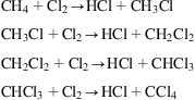
Alternatively, the HCl can also be obtained from the chlorination of alkanes as a byproduct:
4.2.5.5 Production of lime from calcium carbonate
In Solvay’s process, calcium carbonate is used to produce a dilute stream of carbon dioxide for the carbonation process. The reaction is at equilibrium:
To drive the equilibrium to products, the furnace operates at 1000–1200°C. There are a number of furnace designs (see also Fig. 4.27):

• Tank furnace: The product is low-purity CaO.
• Rotatory furnace: By feeding the gases and the calcium carbonate in countercurrent, the purity of the CaO produced is higher.
• Fluidized bed furnace: These are capable of producing the highest purity of CaO; the unit has the solids in suspension inside so that the rock decomposes.
Example 4.11
In Solvay’s process, calcium carbonate is used to produce CO2 for the carbonation of the ammoniacal brine in a vertical continuous furnace. Flue gas is burned to generate the energy. The gas products are in countercurrent to the rock. The calcium carbonate is fed at 25°C and the lime exits the furnace at 900°C. The gas products leave the furnace at 250°C and the flue gas is fed at 725°C. Its composition is 9% CO2, 2% O2, 14% CO, and 75% N2, and it is burned with a theoretical amount of air. The combustion is complete. Determine the flowrate of flue gas required (under standard conditions) to calculate 100 kg of calcium carbonate, assuming no energy loss and ignoring the moisture of the flue gas.
Solution
The problem is formulated as a mass and energy balance. The energy required for the decomposition of the calcium carbonate,
is obtained by burning the CO in the flue gas:
Furthermore, the flue gas is fed at a certain high temperature. The gas products leave at 250°C, but CaO and the air also need energy.
Thus the energy balance of the furnace is as follows:
The energy required for the decomposition of the CaCO3 is its formation heat. Since we process 100 kg of it, 1 kmol is our basis for the calculations:
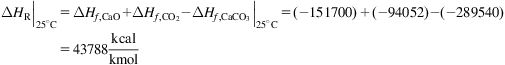
The reaction does not take place at 25°C, and the CaO exists at 900°C with no phase change:

For the CO2 we also need to adjust the enthalpy calculation since the CO2 leaves at 250°C with the product gases:

The total energy is the addition of the three terms:
The energy is provided by burning the CO. Using a basis of 100 kmol of flue gas, we have 14 kmol of CO, for which we need 7 kmol of O2. We already have 2 kmol, and the rest (5 kmol) should come from the air. The composition of the air is 21% oxygen and 79% nitrogen. Thus:
The energy provided by the combustion of CO at 25°C and 1 atm is computed as:

However, the nonreacting species exit at 250°C while they are fed at different temperatures. Air enters at 25°C and must be heated up to 250°C. The flue gas enters at 750°C and the unconverted gases leave at 250°C. Oxygen is assumed to be completely consumed:

The product gas, per consists of N2 and CO2. The CO2 produced in the decomposition of the calcium carbonate is already accounted for:

The only variable is the mass of flue gas Ca2CO3:
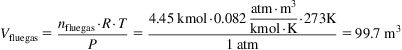
Thus the moles of flue gas are given as follows:
The energy balance can be formulated in a different form:


Since air and CaCO3 are at ambient temperature, the balance becomes:

Now we compute the needs of the air and the gas products as a function of the feed of flue gas:

Using these definitions in the energy balance, it becomes:

Thus we can solve for the moles of flue gas:
The capture of CO2 during the production of lime from calcium carbonate is an additional feature since the process is an equilibrium that can be displaced onwards and backwards under the proper operating conditions. Lately it has been used as a carbon capture technology. The equilibrium vapor pressure of CO2 can be computed using Eq. (4.28):
(4.28)
Using it we produce Fig. 4.28. Above the line, for high pressure, we have the carbonation reaction:

Below the line, calcination governs:
Therefore we can propose a flowsheet for the capture and regeneration of the bed as in Fig. 4.29. The flue gases containing the CO2 are fed to the carbonator where a bed of CaO is made to react with the incoming CO2. The operating conditions are 650–700°C. This reaction is exothermic, generating 170 kJ/mol. The products of the reaction, CaCO3 and CaO, are send to calcination. The decomposition of the calcium carbonate is endothermic, and coal and oxygen are fed to produce the energy to regenerate the CaO and produce a concentrated stream of CO2.

4.3 Water–Energy Nexus
Water and energy are two interrelated natural resources. However, for decades water consumption has only been a problem in desert areas, and has therefore received little attention. Its price (low in most developed countries) is not important in economic analyses either. Therefore, only energy consumption and efficiency are accounted for in process design.
The production of energy requires a considerable amount of water. For instance, the production of power in thermal plants requires around 2 L/kWh. In this particular case, the water consumed is mostly that amount lost by evaporation in the cooling tower. In the production of petrol or diesel, there is a certain amount of water injected to extract the crude, around 2.5 L/L. These two examples show that although there is a strong link between both resources, each product and process determines the actual value, and most importantly, where it is possible to implement further water- and energy-saving technologies. When it comes to renewable resources, the use of water is more important since we need it to grow the crops in the case of biomass-based fuels and chemicals; it can be a limiting raw material in solar processes. The proper allocation of the facility has a large impact on water consumption. Native regions for crops do not require irrigation; for instance, no freshwater consumption is reported for the sugar cane produced in Brazil, which is the raw material of choice for the production of ethanol in that country. When it comes to solar energy, its availability is inversely correlated to water. Thus, concentrated solar power facilities require a fair amount of water if a wet cooling cycle is used, like in thermal power plants. Alternatively, dry cooling systems such as A-frames can be used. These systems consume 5–10% of the energy produced in the facilty for powering the fans—reducing the efficiency of the process—but they do not require water.
While on the one hand energy production (or fuels) requires energy, on the other hand energy is required to treat and transport water. The water used in any process comes out with increased levels of chemicals, particles, etc. This water needs to be reintegrated into the system to reduce the actual consumption, and for that the levels of contaminants must be reduced to the levels established by environmental regulations. Furthermore, water desalination is the only source of fresh water in many regions of the world, and it is an energy-intense process (Martín and Grossmann, 2015).
4.4 Problems
P4.1. To process a mixture of water and NaCl using reverse osmosis, a minimum theoretical pressure of 15 atm is required at room temperature. Determine the minimum pressure required to process a mixture with twice the NaCl concentration. The dissociation of NaCl is as shown in Table P4.1.
P4.2. A solution of NaOH is to be produced from a solution of sodium carbonate with the mass composition given in Table P4.2.1.
The carbonate solution is processed with a mixture of CaO, CaCO3, and calcium hydroxide to obtain a product with the composition shown in Table P4.2.2.
Per 100 kg/s of product:
1. Determine the amount of sodium carbonate solution.
2. Determine the amount of calcium mixture required.
3. Determine the limiting and excess reactants and the percentage in excess.
4. Compute the conversion of the process.
P4.3. In the production of CO2 within the Solvay process, calcium carbonate with 100% purity is used. It is fed in countercurrent into a vertical furnace with a flue gas to be decomposed. The gases exit from the top of the furnace while the solids (CaO) are collected at the bottom. CaCO3 is fed at 25°C and the CaO leaves at 900°C. Gas products leave the furnace at 250°C, and the flue gas is fed at 600°C with the following composition: 10% CO2, 15% CO, and 75% N2. Air is fed at 25°C in stoichiometric proportions to burn it. The combustion of the flue gas is complete. Compute the flowrate of flue gas in standard conditions to process 100 kg/s of CaCO3. Assume that heat loss and gas moisture are negligible.
P4.4. A single-stage evaporator has a contact area of 30 m2. It is used to concentrate 4000 kg/h of NaOH solution from 10% to 40% that is fed at 60°C. The hot utility is saturated steam that condenses at 115°C. In the evaporation chamber, the total pressure is 20 mmHg. A flow of 4000 kg/h of steam is required for the operation; see Fig. P4.4. Determine:

P4.5. A facility manager believes that the alkali solution they are buying does not meet specifications. It consists of NaOH, Na2CO3, and water. It reacts with a lime solution whose composition is given in Table P4.5.1.
The product has the composition given in Table P4.5.2.
Evaluate, for 100 kg of product:
1. Amount and composition of the alkali solution.
2. Amount of commercial lime required.
3. Reactant in excess and percentage in excess.
P4.6. Calcium carbonate (100% purity) is fed to a vertical furnace in countercurrent with a flue gas to be decomposed for the production of CO2 for the Solvay process. The resulting gases exit from the top of the furnace while the solids (CaO) are collected at the bottom. CaCO3 is fed at 25°C and the CaO leaves at 875°C. Gas products leave the furnace at 225°C, and the flue gas is fed with the following composition: 10% CO2, 15% CO, and 75% N2. Air is fed at 25°C in a stoichiometric proportion to burn it. The combustion of the flue gas is complete. 5 kmol/s of flue gas are required to process 100 kg/s of CaCO3. Assume that heat loss and gas moisture are negligible. Determine the inlet temperature of the flue gas.
P4.7. A solution of NaOH and CaCO3 is to be produced by mixing an alkali solution (84.526% water and the rest NaOH and Na2CO3) with a commercial lime solution ((Ca(OH)2+CaO) that contains CaCO3 as an impurity). The product has the composition given in Table P4.7. Per 100 kg of product, and considering that we have an excess of Ca(OH)2 of 4.45%, determine:
1. The amount and composition of the NaOH+CaCO3 solution.
2. The amount and composition of the commercial lime solution.
P4.8. A single-stage evaporator processes 15,000 kg/s of an NaOH solution that is fed at 40°C. The solution concentration is 10%. Saturated steam at 3.5 atm (138.2°C and λ=513 kcal/kg) is available as hot utility. It exits as saturated liquid. The economy of the steam is 0.785. The vacuum at the evaporation chamber is 620 mmHg with respect to 1 atm. The global heat transfer coefficient is 1600 kcal/m2 h°C. Assuming no heat loss, compute: (a) hot utility flowrate, (b) evaporator surface area, and (c) composition of the concentrated solution.
P4.9. Compute the optimal ratio of NH3 and NaCl to be fed into a Solvay Tower for maximum Na2CO3 production. Determine the amount of NaHCO3 produced per ton of NaCl fed, the calcium carbonate consumed in the process, as well as the Na2CO3 produced.
P4.10. We would like to produce a flowrate of 2 kg/s of hydrogen at 30 bar via water electrolysis using different energy sources: solar, wind, or biomass. The oxygen produced must be compressed up to 100 bar for its storage. The compressors behave as polytropic, with an efficiency of 85% and k=1.4, and the electrolysis takes place at 80°C, consuming 175.000 kJ/kgH2. Assuming ideal water split so that we obtain pure hydrogen from the cathode and pure oxygen from the anode:
a. Determine the energy required for the process.
b. Suggest the best technology (see Table P4.10 for the processing parameters).
c. Determine the cost of wind energy so that it becomes competitive, assuming a carbon tax of 40€/t of CO2 and the fact that the ground required costs 25€/m2.
P4.11. A certain renewable source of energy produces 50,000 kW during June. We would like to use it to produce hydrogen. Hydrogen has to be compressed up to 30 bar and the oxygen is sold at 100 bar. Assuming perfect water splitting, pure hydrogen and oxygen streams from cathode and anode, respectively, a polytropic (k=1.4) efficiency of 85% for the compressors, and the fact that the electrolysis takes place at 80°C and consumes 175.000 kJ/kgH2:
a. Compute the flow rate of hydrogen produced.
c. Determine the cost of wind energy so that it becomes competitive, assuming a carbon tax of 40€/t of CO2 and the fact that the ground required costs 25€/m2 (Table P4.11).
P4.12. Determine the ratio and amounts of NaCl and NH3 to produce 10 kg/s of Na2CO3 using Solvay’s process. The equilibrium in the tower yields 0.3 mol of NaHCO3 per mol of initial mixture. Also compute the CO2 required for the process and the calcium carbonate needed for the production of the Ca(OH)2 used for ammonia recovery.
P4.13. A membrane module is available for the purification of a brine that contains 30,000 ppm of NaCl. We need to process 1000 kg/h, and the permeate represents 75% of the initial flow. The concentration of the permeate must be 200 ppm of NaCl. Determine the average pressure applied to the feed side. The discharge occurs at atmospheric pressure.
Water permeability is 2.05×10⁻⁶ kg/m2 s kPa.
Salt permeability is 4.03×l0−5 kg/m2 s.
P4.14. The production of a solution of 35% HCl from hydrogen and chlorine is attempted. The gas product from the reaction has 95% HCl, and it is absorbed in water (see Fig. P4.14). Compute:
a. The temperature of the converted gases and the energy to be removed from them.
b. The energy removed so that the HCl is fed to the absorption tower at 25°C.
c. The water used in the process.
d. The heat removed for the absorption tower to operate isothermally.
Table P4.5.2
| Species | (% w) |
| CaCO3 | 13.48 |
| Ca(OH)2 | 0.61 |
| Na2CO3 | 0.36 |
| NaOH | 10.96 |
| H2O | 74.59 |
Table P4.7
| Species | (%) |
| CaCO3 | 13.48 |
| Ca(OH)2 | 0.61 |
| Na2CO3 | 0.28 |
| NaOH | 10.36 |
| H2O | 75.27 |
Table P4.10
| Technology | Cost (€/kW) | CO2 Produced (kg/kW) | Area (m2/kW) |
| Wind | 1300 | 0.5 | 0 |
| Solar | 1150 | 1 | 5 |
| Biomass | 1000 | 0 | 10 |

Table P4.11
| Technology | Cost (€/kW) | CO2 Produced (kg/kW) | Area (m2/kW) |
| Wind | 1300 | 0.5 | 0 |
| Solar | 1150 | 1 | 5 |
| Biomass | 1000 | 0 | 10 |


P4.15. At what potential is Cl2 released from an electrolytic cell that processes a solution of NaCl, 0.5 M?
P4.16. A certain renewable source of energy produces 75,000 kW during June. We would like to use it to produce hydrogen. Hydrogen has to be compressed up to 30 bar, and the oxygen is sold at 125 bar. Assuming perfect water splitting, pure hydrogen and oxygen streams from cathode and anode, respectively, a polytropic (k=1.4) efficiency of 85% for the compressors, and the fact that the electrolysis takes place at 80°C with an energy ratio of 66%:
a. Compute the flowrate of hydrogen and oxygen produced.
b. Select a technology considering a carbon tax for emitting CO2 of 40€/t and a cost for ground of 25€/m2 (Table P4.16).
Table P4.16
| Technology | Cost (€/kW) | CO2 Produced (kg/kW) | Area (m2/kW) |
| Wind | 1300 | 0.5 | 0 |
| Solar | 1150 | 1 | 5 |
| Biomass | 1100 | 0 | 10 |

P4.17. An electrolytic cell is used to produce syngas for ammonia synthesis. Nitrogen comes from air separation while hydrogen is produced from water electrolysis. Hydrogen needs to be compressed up to 300 bar and the oxygen is stored at 125 bar. Assuming perfect water splitting, pure hydrogen and oxygen streams from cathode and anode, respectively, a polytropic (k=1.4) efficiency of 85% for the compressors, and the fact that the electrolysis takes place at 80°C with a current efficiency of 66% (Table P4.17):
a. Compute the power required to obtain 50 kmol/s of syngas in stoichiometric proportions.
b. Select the appropiate technology.
P4.18. Syngas for the production of methanol is obtained from C and water in two processes in parallel.
– Using 10 kmol/s of C, the water gas cycle is used. Only 70% of the steam reacts with C. The WGSR equilibrium is established at 900K among the gases from the previous reaction. Assume the following equation for the equilibrium constant:
– The proper H2-to-CO ratio in the final mixture is obtained by mixing the resulting gas with hydrogen from electrolysis. The hydrogen must be compressed up to 50 bar and the oxygen stored at 125 bar. Assuming perfect water splitting, pure hydrogen and oxygen streams from cathode and anode, respectively, a polytropic (k=1.4) efficiency of 85% for the compressors, and the fact that the electrolysis takes place at 80°C with a current efficiency of 66%, compute:
a. The composition of the gases from the water gas cycle.
b. The fraction of H2 in the water cycle and that provided in electrolysis.
c. The energy required for electrolysis and compression of the gases.
P4.19. A single-stage evaporator system is used to concentrate 10,000 kg/h of an NaOH solution from 10% to 35%. The feed is heated up using the residual heat from the condensed steam before entering the evaporator. The concentrated solution is cooled down using water in a second heat exchanger. Finally, the evaporated water is condensed in direct contact with water (see Fig. P4.19).
The hot utility is a saturated steam at 3.2 atm, which condenses at the evaporator and exits the heat exchanger at 40°C. The evaporation chamber is maintained at 150 mmHg vacuum with respect to 760 mmHg. The liquid from the direct contact cooling device is at dew point. The NaOH solution is fed to the system at 20°C and to the evaporator at 50°C. The cooling water used to cool down the concentrated solution enters at 20°C and leaves at 35°C. The global heat transfer coefficient is 2000 kcal/(m2 h°C). Determine:
e. Area of the heat exchangers. The global heat transfer coefficients are 800 and 400 kcal/ (m2 h°C) for the feed heated and the solution cooler, respectively.
P4.20. A single-stage evaporator system is used to concentrate 10,000 kg/h of a NaOH solution from 10% to 45%. The feed is heated up using the residual heat from the condensed steam before entering the evaporator. The concentrated solution is cooled down using water in a second heat exchanger. The hot utility is a saturated steam at 3.5 atm, which condenses at the evaporator and exits the heat exchanger at 35°C. The evaporation chamber is maintained at 150 mmHg vacuum with respect to 760 mmHg. The NaOH solution is fed to the system at 20°C and to the evaporator at 45°C. A cooling water flowrate of 15,728 kg/h is used to cool down the concentrated solution, enters at 20°C, and leaves at 30°C. The global heat transfer coefficient is 1500 kcal/(m2 h°C). Determine:
c. Area of the heat exchangers. The global heat transfer coefficients are 650 and 125 kcal/(m2 h°C) for the feed heated and the solution cooler, respectively.
P4.21. A membrane module is available for the purification of a flow of brine that contains 30,000 ppm of NaCl. We need to process 1000 kg/h, and the permeate represents 75% of the initial flow. The concentration of the permeate must be 200 ppm of NaCl. Determine the average pressure applied to the feed side. The feed is at 9000 kPa and the concentrate at 8500 kPa. The discharge of the permeate occurs at atmospheric pressure.
Water permeability is 2.05×10⁻⁶ kg/m2 s kPa.
Salt permeability is 4.03×10⁻⁵ kg/m2 s.
P4.22. Compute the needs of calcium carbonate and flue gas, with the composition 2% O2, 78% N2, and 20% CO required to operate a Solvay-based facility that produces 10 kg/s of sodium carbonate. The facility uses an excess of 10% molar NaCl. The furnace is fed with calcium carbonate, 100% at 25°C. The lime exits the furnace at 900°C. The gas products leave the unit at 250°C and the flue gas is fed at 600°C. The air used is at 25°C and assumed to be dry. Combustion is complete.
Table P4.17
| Technology | Cost (€/kW) | CO2 Produced (kg/kW) | Area (m2/kW) |
| Wind | 1250 | 0.5 | 0 |
| Solar | 1150 | 1 | 5 |
| Biomass | 1100 | 0 | 10 |

