
4. The Motion Data
Motion Data Types and Formats
Depending on the system you are using, you will have to deal with several different motion data file formats. Real-time systems usually generate a stream of data that can be used directly in the animation software with the help of special plug-ins. Some optical systems' data is also generated in real time but in most cases it is not, so it won't be streamed into the animation software, but rather imported from a data file. Most computer graphics packages such as Maya or three-dimensional Studio Max already have converters that will allow you to import data files in several file formats, but for the sake of character setup, it is important to know what data items the files contain. In addition, none of these files has any information that pertains to the deformation of the character's surfaces, but rather the mechanical aspects of rigid segments. All deformations are specific to the animation software to be used.
All these data files go through a few stages before becoming final. First, as the data is collected a stream file is created. This is what we call raw data. In the case of optical systems, a file is created for each of the system's cameras containing the raw images in a format specific to the manufacturer. It may contain just black-and-white or grayscale images, or maybe no images at all but some smaller representation of the camera's view of the marker cloud, like a series of 2D coordinates. If this is the case, it means that the camera did some processing of the images before sending them. This is done to accelerate the process and it is part of how optical systems today can achieve some kind of real-time feedback, but the downside is that the system doesn't keep the data in its original form. These files are the ones that, in combination with a file containing the calibration of the capture volume, will be used to track the 3D data.
The second stage is the file generated after tracking the position of each point, which contains the Cartesian coordinates of each of the markers. The data in this file is called global translation data, as it represents the position of each marker in reference to the world origin, without including any hierarchy or skeleton definition. I will refer to this type of file as translational, because it contains no rotations, only translations of independent points in space. This type of file can already be used for performance animation, but there are other levels of simplification: files that contain data based on segments or limbs rather than points. There are two data types that meet this description, the hierarchical segment translation and rotation and the global segment translation and rotation. Both of them are based on a definition of a skeleton to be used for driving the motion of the character and are created by combining the points in the translational file. In the hierarchical rotational file, mostly the root point has rotations and translations and the rest have only initial local translations that define the length of each segment, plus a stream of local rotations. There is also a set of scale channels that represents the variation in length of each segment. This is necessary because the segments are not exactly rigid, as the markers have to be placed over skin or clothes. This channel also helps in the determination of data accuracy. The global rotational file contains translations, rotations, and scale channels for each independent segment, and there are no dependencies between them.
Rotational files are generally easier to use than translational files because most of the work in setting up a skeleton has already been done; however, translational files allow you to create better and more complicated character setups. Only experienced users should work with translational data. In addition, because translational files contain no rotations, they are less prone to common problems associated with Euler angles' transformations.
For many years, the primary data file format used for optical motion capture was the Acclaim .amc and .asf combination, but today it is the .C3D format. Other file types used are the Biovision .bva and .bvh files and the Motion Analysis .trc and .htr formats. Many companies have special file formats that fit their particular needs. At Tsi, for example, we had the .tsi file, a binary file that was better suited for fast random access, an essential item in video games and data editing tools. Some of these files are rotational and others translational and they're all delimited by tabs. We will later explain each one in detail.
Bringing these files into animation software successfully is not always as easy as it seems. Many times, the file has to be prepared with certain constraints based on particularities of the individual animation program. Other times, the program has to be configured in a certain way to be able to receive the data properly. The first usual restriction has to do with world space. Some animation programs like Y to be the axis going in the up or down direction, while others like Z. Some consider XY as the front plane, while others use XZ. Another common difference between off-the-shelf animation software is the order of transformations and the order of rotations. Most animation programs have a hard-coded order of transformations, others have a hard-coded order of rotations, and the data file must be prepared accordingly. It is not enough to change the definitions in the file; the data must be recalculated as well. One more item to consider is the base position, as some programs require their initial skeleton's zero pose to be aligned in a certain way. In addition, the segment scale specified in some files is totally ignored when the data is imported into some animation programs. Other restrictions include naming convention and units. The easiest type of data to import is the translational, because, since no hierarchy and rotation or scale channels are present, most of the restrictions are not applicable. The down side of importing translational data is that the character setup is much more involved, but, on the other hand, you have better control of what you want to do with the setup.
The .C3D File Format
The biomechanical research community needed a file format that could be used to share and maintain data for many years and across different hardware and software platforms; a standard that could hold all the data pertinent to the field and would not be tied to any particular system manufacturer. The C3D format was first introduced in 1987 by Dr. Andrew Dainis at the National Institutes of Health in Bethesda, Maryland. It was developed as part of a software suite called AMASS (ADTech Motion Analysis Software System). The software was written particularly for optical systems and was adopted first by Vicon as their primary file format. Initially, C3D files were used exclusively in life sciences laboratories for biomechanical studies, but as Vicon systems gained market share in the entertainment industry it also became popular in video game, film, and television applications and is now supported by most animation software.
The C3D file format is binary and it is designed to hold all pertinent data in a single file, as opposed to other formats that hold only certain data and others that require more than one file to store all the information. A .C3D file can even hold user-specific information such as the performer's name, medical diagnosis, or any other specific information. It is divided into three sections: Header, Parameter, and Data. Each section comprises one or more 512-byte blocks.
The .C3D Header Section
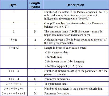
The .C3D header is the first 512-byte block in the file. The table in Figure 4.1 shows the information that can be found in the header.
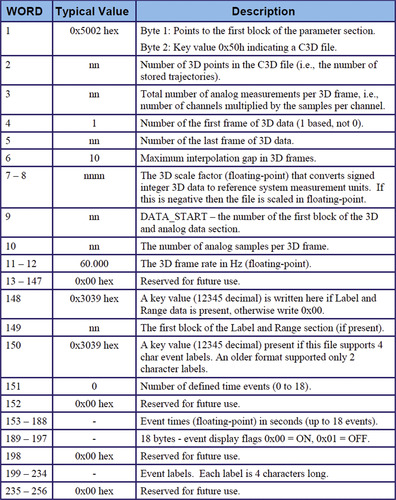 |
| Figure 4.1 The .C3D file header record (Motion Lab Systems, 2008). |
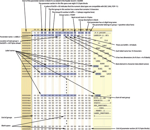
Many of the fields in the header are not that relevant to entertainment application. Figure 4.2 is a sample hex dump that shows the most important ones.
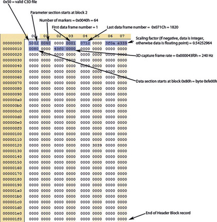 |
| Figure 4.2 Hex dump showing important fields in .C3D file header record. |
The .C3D Parameter Section
The parameter section consists of a series of 512-byte blocks that contain all the parameters that would be necessary to use the data included in the data section. The length of this section is variable in the number of blocks, but each block must be 512 bytes long.
The data contained in this section varies, but it is usually the name of the markers, descriptions, data types, groupings, etc. Each parameter belongs to a group and contains a name and a data type and can also have other elements, such as a detailed description.
The section starts with a 4-byte header. After the header, the first group record is listed, followed by all the parameters that belong to the group. After that, we find the next group and all its parameters. This will continue until all the groups and parameters are listed.
Figure 4.3 is a table that shows the layout of the parameter section header. The first 2 bytes are typically not used, but some legacy software will look for a copy of the first 2 bytes in the file header section.
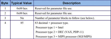 |
| Figure 4.3 The .C3D parameter section header record (Motion Lab Systems, 2008). |
After the header, we have the first group record as shown in Figure 4.4.
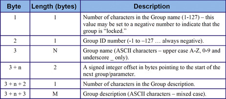 |
| Figure 4.4 The .C3D parameter section group record (Motion Lab Systems, 2008). |
Each group contains a number of parameters, each of which has a parameter record (Figure 4.5).
 |
| Figure 4.5 The .C3D parameter section parameter record (Motion Lab Systems, 2008). |
The hex dump in Figure 4.6 shows an example of a parameter section.
 |
| Figure 4.6 Hex dump describing important fields in the parameter section. |
The .C3D Data Section
Like the parameter section, the data section consists of a number of 512-byte blocks. It contains the actual position measurements as specified in the header and parameter sections.
Each data point or marker coordinate is stored in a record. If the data format is floating point, each record will contain 16 bytes. If the data format is integer, the record will contain 8 bytes. The data format is specified in the header section as part of the scaling factor.
The number of records will be defined by the number of frames specified in the header section by the number of markers that we can find in the parameter section. In the case file we have been studying, there are 1820 frames and 64 markers, which is equal to 116,480 records.
Figure 4.7 shows the .C3D data section for floating-point data. Note that the record includes information about the cameras that contributed to the calculation of the point's coordinates and also a residual value, which is a measurement of the accuracy of the data.
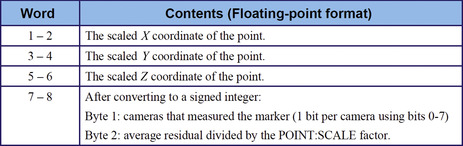 |
| Figure 4.7 The .C3D data section record for floating-point data (Motion Lab Systems, 2008). |
The Acclaim File Format
The Acclaim file format was developed by Acclaim and Biomechanics, Inc., for Acclaim's proprietary optical motion capture system. The file format is the most comprehensive of all mainstream nonbinary formats and is supported by a large majority of commercial animation applications.
The format is based on a combination of two files, Acclaim Skeleton Format or .asf and Acclaim Motion Capture or .amc. The first file deals primarily with the definition of a hierarchy of rigid segments or skeleton, while the second one contains the actual data associated with the skeleton. Multiple .amc files can be associated with one single .asf file, and this can be beneficial for complicated character setups. Acclaim files can contain translational or rotational data, although rotational is the most commonly used.
The .asf File
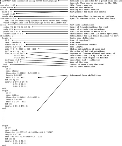
The .asf file is much more than just a definition of hierarchy. It contains all information pertaining to the mechanical function of the skeleton, including units, multipliers, degrees of freedom, limits, and documentation. The only item not included in this file is the data itself, but it does include the initial pose or the base position that is used for character setup. All the data in the associated .amc files is relative to the base position specified.
The file is divided into eight sections identified by the following keywords preceded by a colon: version, name, units, documentation, root, bonedata, hierarchy, and skin.
 |
 |
The units section contains three fields, mass, length, and angle. Mass is usually ignored by animation software, but it is a multiplier for segment mass. Length is a multiplier for the bone's length. The angle field specifies whether the orientation data is given in degrees or radians.
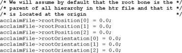
The entire hierarchy is relative to the position and orientation of the root, which has an order of transformations and a separate axis order that defines its initial orientation; however, the bone definitions are specified in global space; the direction vector and axis are not relative to the root, but to the world axis.
The dof field is the specification of the allowed degrees of freedom for the particular segment, which can be any or all of tx, ty, tz, rx, ry, rz, and l. The latter is a translation value along the segment's length, and a variation in this field's data indicates that the segment is not rigid. These variations can be used in the animation to stretch and compress the character's skin, but they should be reasonably low. The dof tokens are optional and can be specified in any order, which will define the order of transformations for the segment.
In many cases, all translations are omitted from the child segments, except in the case where the file contains translational data only. In this case, the rotation and length degrees of freedom would be omitted. In a rotational file, even if a bone, such as the elbow, is supposed to be unable to rotate toward a certain orientation, I don't recommend omitting any of the rotation degrees of freedom, because the joints are never totally confined.
The limits are used to constrain the motion of a particular degree of freedom, and are specified in the same order as the dof tokens, in pairs of minimum and maximum. The .amc file in most systems is generated within these limits. It is not recommended to constrain motion data, unless it is absolutely necessary. This is most applicable in real-time nonlinear video game applications, but there are other cases where it may be desirable.
Many of the fields in the .asf file are used differently by different entities, and some have added new fields for special purposes. The optional skin section, for example, can be used by animation software to load one or more specific models. Bodymass and cofmass are fields used by some systems to calculate certain segments' dynamic characteristics that can be used to implement alternate procedures, such as hair and clothing. The norm is that if a field is not recognized, it is ignored. In addition, special considerations have to be taken into account as preparing an .asf file for importing into animation software. Some programs require different order of rotations or have a differently oriented world axis, and this has to be taken into account before creating the .asf and .amc files.
The .amc File
The .amc file contains the actual motion data stream. All the data in this file is relative to the definitions in the .asf file, and the fields are sequenced in the same order as the dof field in the .asf file.
 |
 |
A clear advantage that the Acclaim file has over other formats is that each of the bones or segments can have a different order of transformations, while other formats specify an order of rotations that applies to all segments, and assume that translations occur before rotations. In addition, the Acclaim format can contain translational and global rotational data as well as hierarchical rotational data without the need for changing file formats.
The .bva File Format
This format was created by Biovision, an optical motion capture studio that specialized in sports analysis and animation.
This file is very simple because it lists all nine possible transformations without allowing for any changes in order. Also, each segment's transformations are absolute, or relative only to the world axis, so no hierarchy is necessary.
No header is present, but only clusters of lines that denote each segment, with the motion data laid out in columns that represent each transformation.
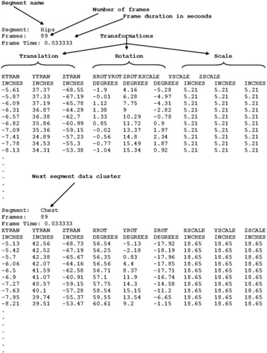 |
Each cluster contains, in addition to the transformations, a segment name, the number of frames, and the frame duration in seconds. In the earlier example, each frame has a duration of 0.033333 s, which also means that the data is supposed to be played back at 30 frames per second.
The scale transformations in the example are all equal for each segment, which means that the segment is rigid throughout the whole data stream. Having three scale transformations is redundant, as only one is required to specify the length of the segment. Note that the example contains equal values on each of the three scale values, so that the target animation software can use the preferred one.
The .bvh File Format
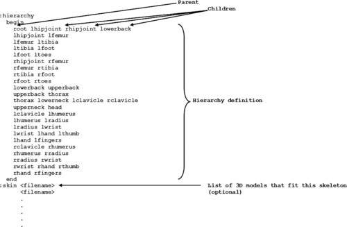
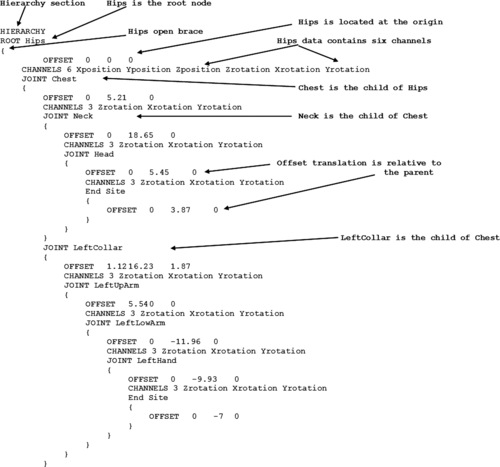
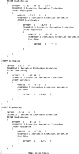
Another Biovision format, the .bvh file is more widely supported than the .bva file. Three-dimensional Studio Max and Nichimen, among others, are able to import this file type. The main difference between the .bvh and the .bva file is that the former includes a hierarchy. It is divided into two major sections, hierarchy and motion. The hierarchy section includes all necessary definitions to create a skeleton in animation software. The motion section contains the data stream.
The hierarchy is defined within blocks of braces. Within each node's braces are defined all of its children, which have their own subblocks.
 |
 |
 |
Each node has an offset field that defines its translation relative to its immediate parent node, except for the root, where the offset is absolute. In the aforementioned example, the node Chest is located at 5.21 units in the Y direction from its parent, Hips. The offset order is always XYZ and no orientation is specified. These values also help define the length of the parent segment, but only in the case where there are no siblings in different locations. There is no assumption in the hierarchy section about the initial orientation of any node, including the root, and that leaves it open for interpretation by the animation software. The .bvh file has to be prepared with this in mind.
There are brace blocks located at the deepest levels of the chain called End Site, which contain only an Offset field. This offset value is there to define the length of the last segment in each particular chain.
The Channels field serves two purposes: First, it defines the allowed transformations for each segment in particular, and second, it defines the order of occurrence of the transformations. Usually, only the root has any kind of translation, and no scale is used, so all segments are assumed to be rigid. The rest of the segments most of the time contain only rotations. The omission of a scale field makes it difficult to assess each segment's approximation to rigidity, a good measure of margin of error for captured motion data. It is only visually that we can estimate the lack of distortion of the motion due to marker misplacement or tracking errors.
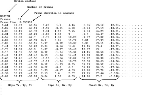
The Motion section is laid out by column per channel, in the order defined by the hierarchy section. The first fields define the number of frames and the time per frame. In the earlier example, there are 89 frames that last 0.033333 s each.
Each of the following lines contains a frame of animation for each of the channels defined in the hierarchy section, and in the same order. The number of these lines is equal to the number of frames specified.
The .trc File Format
The .trc file is generated by Motion Analysis optical motion capture systems and contains translational data. The first part of the file is a header with global information, such as the sample rate of the data in the file and at the time of capture, the number of frames and markers, measure units, and file path.
 |
The file header shown not only shows the current state of the data, but also of the original data captured. The data was originally collected at 60 samples per second and the first file generated had 600 frames, or 10 s. The final file was sampled down to 30 samples per second and shortened to 55 frames, for a resulting total of 1.83 s. This is good to know because in case we decide we need more data for this particular motion, we can always go back to the original file.
Right after the header we find the data section. It is organized in columns, the first two being the frame number and the elapsed time, followed by the X, Y, and Z coordinates for each of the markers. The sample file has a total of 74 columns, but we can only display a small portion of it.
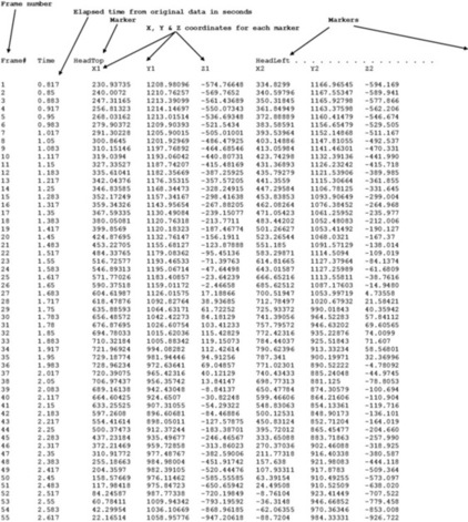 |
Notice that the elapsed time in the sample file starts at .817 s. That means that the first portion of the original 60 samples per second file was cropped after frame 49. If we wanted to go back to the original file, we have all the information necessary to relocate the segment we want.
The .htr File Format
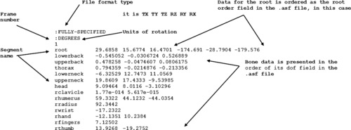
This file is generated by the Motion Analysis optical motion capture system, and contains rotation, translation, and scale channels per marker. It is divided into four parts: the header, the segment hierarchy definitions, the base position, and the data stream.
This sample .htr file was converted from the .trc file in the previous section and it has 55 frames as well. It has only 24 segments in order to simplify the analysis. We will first look at the header portion.
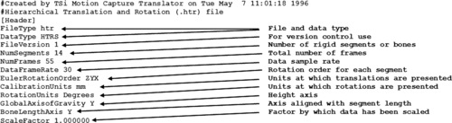 |
The Euler rotation order is important because each segment's orientation is obtained by three successive rotations in a particular sequence. The decision as to what order of rotations will be used must be reached before generating the .htr file. It depends largely on the animation software to be used because some off-the-shelf animation programs have hard-coded the default rotation order and it cannot be modified by the user.
Other parameters relevant to this type of file are the axis that points in the direction of gravity and the one that points in the length direction of a segment. These are also subject to the animation software defaults. As shown in Figure 4.8, most packages consider Y as the gravity axis (also called up axis), but some use Z. The axis that corresponds to the bone length is Y in most cases, as seen in Figure 4.9.
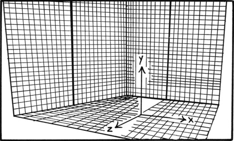 |
| Figure 4.8 Global axis of gravity. |
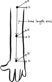 |
| Figure 4.9 Bone length axis. |
The translation data and segment lengths can be scaled to conform to a certain environment size, and the ScaleFactor field is used to keep track of this modification. This factor pertains to all the data and not to particular segments.
Following the header, we have the hierarchy and segment definition section. This is where all the segment names and parental links are defined. All segments are listed in the first column and their parents are listed in the second column. If a segment is listed as global, it means it has no parent. It is possible to list all segments as global, resulting in a stream of global segment rotational data. If a hierarchy is defined, the data falls under the hierarchical segment rotational category. In this case, there has to be at least one segment marked as global.
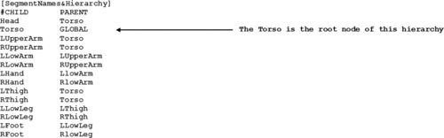 |
Figure 4.10 shows a graphic representation of the hierarchy. The base position is the initial pose that I talked about in Chapter 3. During the motion capture session, a file with the neutral pose is captured. A frame in that file is selected to represent the closest pose to the digital character model. This frame will become the common base position and will be embedded into the body of all .htr files as they are generated. The base position is also the initial skeleton of the character in the animation software, so by using a common one for all .htr files, only one character setup is necessary. All motion transformations in the .htr file are relative to this base position. That means that if all translations and rotations are zeroed out, the skeleton will return to this pose. It also means that if the base position is changed, all the data in the file must be recomputed. In Chapter 3, I said that you should not set up your character unless you have already imported a base position file into your animation software. It is possible to avoid this if you can write software to recalculate the data for a predetermined base position based on your character setup.
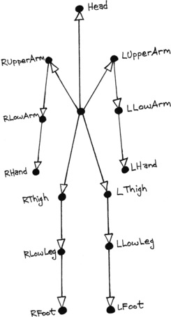 |
| Figure 4.10 Sample file hierarchy representation. |
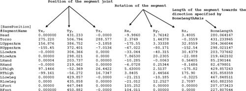 |
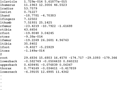
The translation and rotation values of a segment are all relative to its parent. Notice how the value of ty for the head is almost equal to the torso's bone length. That means that the head is almost exactly at end of the torso's segment, and we know that the head is the torso's child. Also, notice how the torso's tx and tz values are much higher than all others are. This is because the torso is the only global segment, and its transformations are all relative to the world axis, while the transformations of all other segments are relative to their direct parents. The only value that is not relative is the bone length.
The fourth section of the .htr file is the data itself. It is divided into subsections per segment, each line representing a frame number.
 |
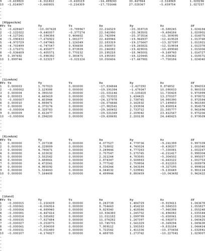 |
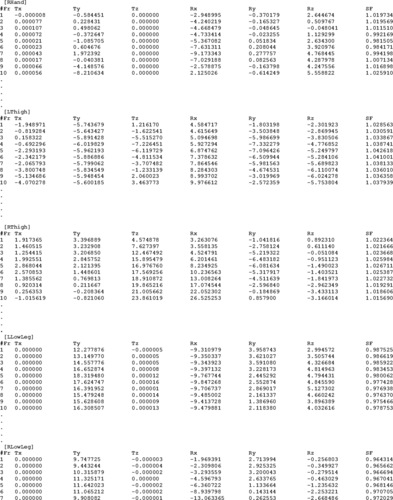 |
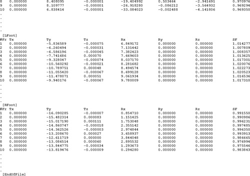 |
The SF column in the .htr file is a scale of the particular segment along the axis indicated by BoneLengthAxis. This number represents deviations in the length of the bone caused by the sliding of the skin over the bone. This number must always be very close to 1.0; otherwise, it indicates a faulty marker location or perhaps a marker placed over loose clothing. If the number is very close to 1.0 throughout the whole data stream, you may ignore it or approximate it to 1.0, thus assuming that the segment is rigid.
The chart in Figure 4.11 shows the segment length scale for the sample file. In this particular case, the factor cannot be ignored completely, as some values exceed the acceptable rigidity deviation. The LHand segment, for example, has a peak deviation of almost 30%. In a situation like this, it may be necessary to recalculate the .htr file using a different combination of markers, and if that doesn't work, the motion may have to be recaptured. The acceptable deviation depends on each particular motion, but it should not exceed 10% in any case.
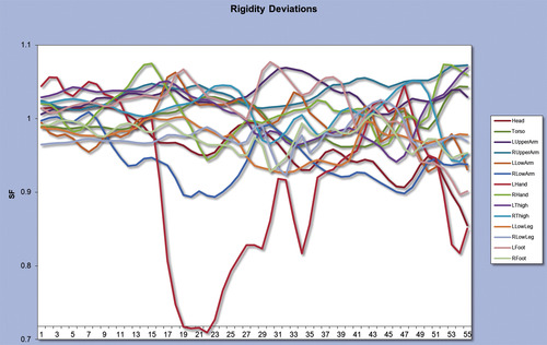 |
| Figure 4.11 Segment length scale. |
Writing a Motion Capture Translator
Most animation programs support at least one motion capture format and it is really unlikely that you may ever have to write your own translator. This section is for you if you are interested in how things work under the hood. The language and platform are not relevant to our discussion, but I will use the C language to illustrate the programming steps. I will also present the code in a sequential way as opposed to modular, as I believe the continuity will aid you in the understanding of the logic. If you decide to write your own translator, you may want to use more functions and subroutines or an object-oriented language such as C#.
As a case study, we will use the .htr format as the input file and the Acclaim format as the output file. I chose Acclaim as the output format because it is the most complicated one that is not binary.
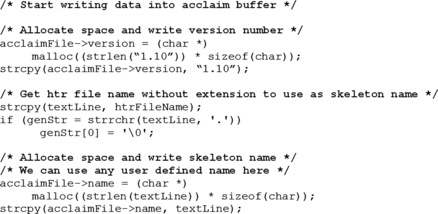
The first step in creating a translator is to define a buffer that will hold all the data of both the input and output files. The .htr file buffer looks like this:
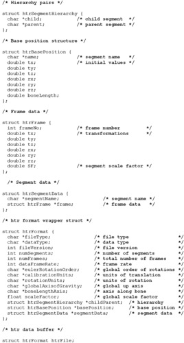 |
htrFile, a variable of type struct hrtFormat, will end up containing the whole data in the .htr file. The first twelve variables in struct hrtFormat correspond to the .htr file's header section. ChildandParent is a buffer that will hold all the child-parent pairs as defined in the SegmentNames&Hierarchy section. This buffer is of the previously defined type struct htrSegmentNamesandHierarchy, that will hold both child and parent strings. BasePosition will contain all the data in the BasePosition section. It is of type struct htrBasePosition, where the segment and initial transformations are defined. Finally, SegmentData, of type struct htrFrame, will hold the motion data.
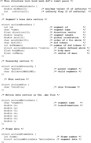
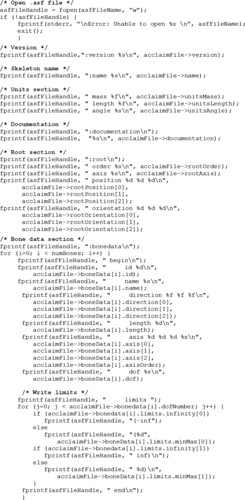
The output file is actually a combination of both .asf and .amc files and we can define its structure as follows:
 |
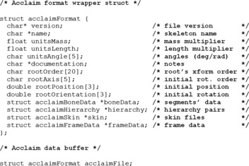 |
acclaimFile will hold all the data in the .asf and .amc files. It is of type struct acclaimFormat. The bone information will be located in boneData, while hierarchy will hold all the parent-child relationships. frameData will contain all the data from the .amc file. Notice in the definition of struct acclaimBoneData that the integer variable dofNumber doesn't actually come from the .asf file. It will contain the number of degrees of freedom available for each particular segment, so that the dof line will be parsed only once per segment. Another special purpose variable is the infinity integer inside the definition of struct acclaimBoneLimits, which, as its name says, will hold a flag to indicate infinity. struct acclaimHierarchy will hold the hierarchy data in pairs of parent and child, as opposed to the way the .asf file holds it, with a parent and all of its children in the same line. If the parent has several children, more than one pair will be generated.
If you compare the aforementioned definitions with the actual file structures as explained in the previous section, you will find that most of the variable and type names are very close to those in the files themselves. You will also find that the structures contain more information that will be used in the conversion from .htr to Acclaim, but including it in the data structure is good practice in case you need it in the future.
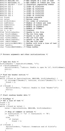
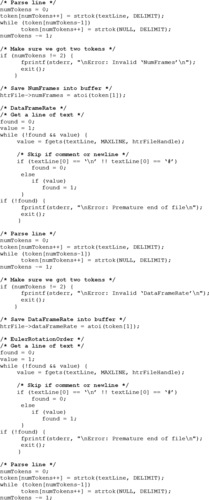
The next step is to start reading the information from the .htr file into the data buffer. Assuming a file is available and its name has already been processed by the program and placed in the string htrFileName, we proceed to open the file and then process the header section:
 |
 |
 |
 |
 |
 |
 |
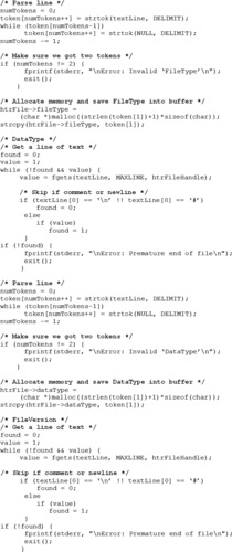
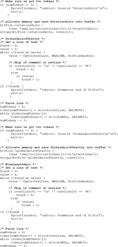
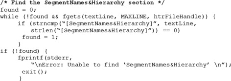
Now we proceed to load the SegmentNames&Hierarchy section into the buffer. The next step after finding the section is to allocate memory for the branch that will hold this data. We can do this now as we already have loaded the number of segments that we need to process.
 |
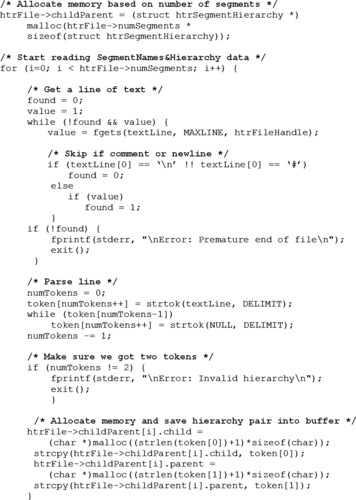 |
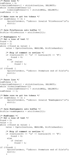
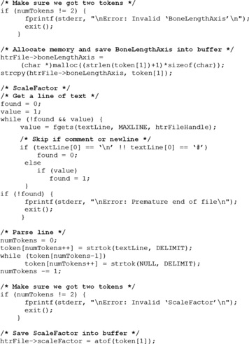
We continue with the base position section. We are now looking for eight tokens per line that represent the segment name, all six transformations and the bone length.
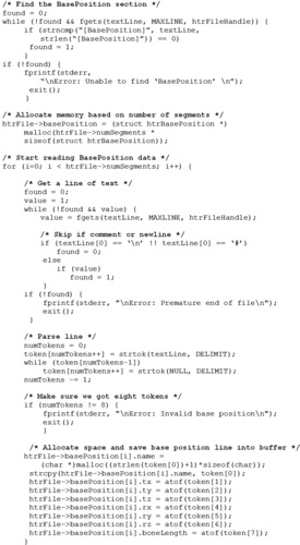 |
The last step in loading the .htr file is the processing of the actual segment data. It also consists of eight tokens, but there is one set of data per frame for each segment. We must allocate space for htrFile→segmentData based on the number of segments, and htrFile→segmentData→frame based on the number of frames.
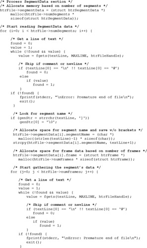 |
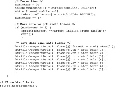 |
We have loaded all of the .htr's file data into memory. At this point, we will start porting the data into the Acclaim format buffer. We could write the data straight into the .asf and .amc files, but moving it first into the buffer will help illustrate this operation in case we decide to write a converter from Acclaim to any other format in the future. If we end up writing a more complicated application where we can port data between several formats, we could perhaps have a different kind of generic buffer where we could save data from any of the file formats. This buffer could be designed in a way that would facilitate other operations as well.
 |
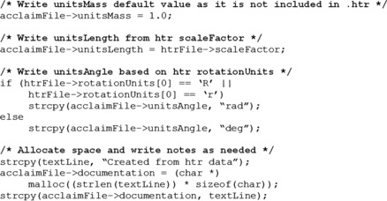 |
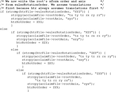
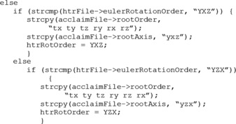
We now write the root section. The order of transformations in the .htr file always includes translations first and then rotations, followed by scale. Because of this, we will assume all translations to occur before all other transformations and include code only to process different rotation arrangements. We also save a predefined rotation order value in htrRotOrder that we will use later, as the .htr file uses one single order of rotations across the board, as opposed to the Acclaim format, where each segment can have a different one.
 |
 |
The .htr file uses an actual segment as the parent of all the hierarchy. In the Acclaim format, we will move the hierarchy one step down, leaving the .htr's parent node as a child of the root node, and we will leave the root node at the origin at all times. This is very useful because we can use the root to add a transformation offset to the whole tree if desired. We could also do this at the animation software level by adding a parent node, but if we are dealing with a great number of motions, it is better to offset all the motion data files.
 |
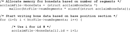
We start saving the bonedata section. We assume that all segments are initially located at the origin, and the length axis is pointing in the GlobalAxisofGravity direction. This part is where some variation can exist between animation software packages, as not all of them assume this to be the initial position of bones. A more elaborate translator should include switches to deal with these software peculiarities.
 |
 |
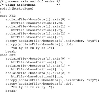
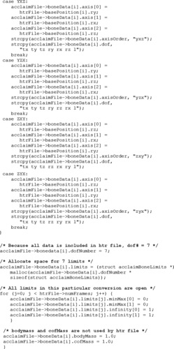
Even though the Acclaim format has the ability to select which transformations are available per segment, we have to include them all, as the .htr file includes all seven transformations for each of the segments. The limits will also be left open, as these are not supported by the .htr format.
 |
 |
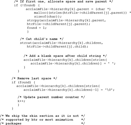
The hierarchy section in the .asf file is quite different from that in the .htr file. The first one lists a parent first, followed by all its children in the same line, while the latter lists each child first, followed by its parent. The number of lines in the hierarchy section of the .htr file is equal to the number of segments, while in the .asf file it is equal to the number of nodes that have children, without counting the root node. This is why, before starting to save the hierarchy in the Acclaim buffer, we must find out how many segments have children.
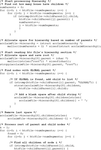 |
 |
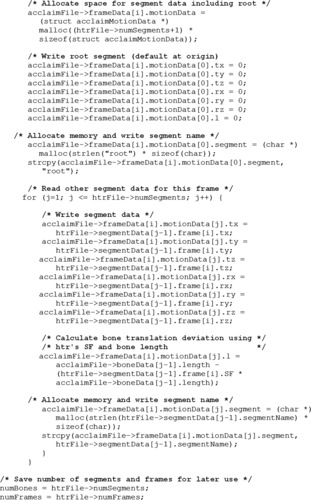
We now start saving the data stream. We will not worry yet about the order of transformations. These will be dealt with when we write the .amc file. The l channel in the .amc data is not the same as the SF channel in the .htr file and it must be converted before saving. SF is a scaling factor or a multiplier for the initial segment length, while l is a translation. This means that an SF value of one is equivalent to an l value of zero. To convert the scaling factor to a translation, we multiply the initial length by the scaling factor and then subtract the segment length, obtaining the difference in length between the initial length and the length for the frame in question.
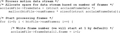 |
 |
We have now saved all the data in the .htr file into the Acclaim buffer. The next step is to write the actual .asf and .amc files. We saved the number of segments in a variable named numBones and the number of frames in numFrames because the Acclaim format does not include a number of segments or frames field.
 |
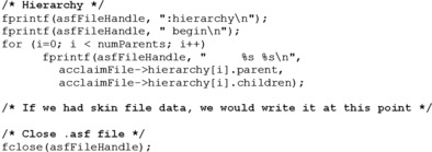 |
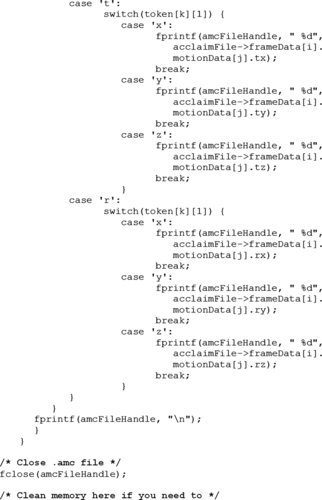
As we write the motion data, we must deal with the order of transformations per segment. We will use the dof field to determine the order per segment.
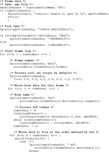 |
 |
..................Content has been hidden....................
You can't read the all page of ebook, please click here login for view all page.