
1. Motion Capture Primer
Chapter Outline
Motion Capture and Performance Animation2
Future Applications45
Motion Capture and Performance Animation
Motion capture is the process of recording a live motion event and translating it into usable mathematical terms by tracking a number of key points in space over time and combining them to obtain a single three-dimensional (3D) representation of the performance. In brief, it is the technology that enables the process of translating a live performance into a digital performance. The captured subject could be anything that exists in the real world and has motion; the key points are the areas that best represent the motion of the subject's different moving parts. These points should be pivot points or connections between rigid parts of the subject. For a human, for example, some of the key points are the joints that act as pivot points and connections for the bones. The location of each of these points is identified by one or more sensors, markers, or potentiometers that are placed on the subject and that serve, in one way or another, as conduits of information to the main collection device. From now on, when speaking generally about these, I will refer to them as “markers.”
Performance animation is not the same as motion capture, although many people use the two terms interchangeably. Whereas motion capture pertains to the technology used to collect the motion, performance animation refers to the actual performance that is used to bring a character to life, regardless of the technology used. To obtain it, one must go through the whole process of motion capture and then map the resulting data onto a 3D character. In short, motion capture is the collection of data that represents motion, whereas performance animation is the final product of a character driven by a performer.
There are different ways of capturing motion. Some systems use cameras that digitize different views of the performance, which are then used to put together the position of key points, each represented by one or more reflective markers. Others use electromagnetic fields or ultrasound to track a group of sensors. Mechanical systems based on linked structures or armatures that use potentiometers to determine the rotation of each link are also available. Combinations of two or more of these technologies exist, and newer technologies are also being tested, all aiming for one result: real-time tracking of an unlimited number of key points with no space limitations at the highest frequency possible with the smallest margin of error. This is the Holy Grail of motion capture and probably the mission statement of every motion capture hardware manufacturer's research department. I later discuss how each of the current technologies falls short in this respect.
History of Performance Animation in the Entertainment Field
The Rotoscope
Motion capture in the entertainment field is the descendant of rotoscoping, a technique still used by some traditional animation studios to copy realistic motion from film footage onto cartoon characters.
The rotoscope device was invented and patented by cartoonist Max Fleischer in 1915, with the intent of automating the production of cartoon films. The device projected live-action film, a frame at a time, onto a light table, allowing cartoonists to trace the frame's image onto paper. The first cartoon character ever to be rotoscoped was Koko the Clown. Fleischer's brother, Dave, acted out Koko's movements in a clown suit. Fleischer wanted to use Koko to convince the big studios to use the new process for their cartoon projects. The sale was difficult because it had taken Fleischer about a year to produce the initial 1-min cartoon using the technique, so he couldn't market it as a mass production tool. Eventually, Fleischer realized that rotoscoping would be a viable technique only for certain shots that required realistic motion.
Walt Disney Studios used some rotoscoping in 1937 to create the motion of human characters in Snow White. Snow White herself and the Prince were partially rotoscoped. The decision to use rotoscoping wasn't a matter of cost, but of realistic human motion. In fact, Snow White went tremendously over budget due to the complexity of the animation.
Rotoscoping has been adopted over the years by many cartoon studios, but few actually admit using it because many people in the animation industry consider it cheating and a desecration of the art of animation.
A two-dimensional (2D) approach, rotoscoping was designed for traditional, hand-drawn cartoons. The advent of 3D animation brought about the birth of a new, 3D way of rotoscoping. Hence, motion capture.
Brilliance
Some of the current motion capture technologies have been around for decades, being used in different applications for medical and military purposes. Motion capture in computer graphics was first used in the late 1970s and early 1980s in the form of research projects at schools such as Simon Fraser University, Massachusetts Institute of Technology, and New York Institute of Technology, but it was used in actual production only in the mid-1980s.
In late 1984, Robert Abel appeared on a talk show and was asked if he would soon be able to counterfeit people digitally. “We are a long ways from that,” he replied. “We haven't even figured out human motion, which is the basis, and that's a year away.” A week and a half later, Abel received a visit on a Friday afternoon from a creative director from Ketchum, a prominent advertising agency. The visitor brought six drawings of a very sexy woman made out of chrome. She was to have Kathleen Turner's voice and would be the spokesperson for the National Canned Food Information Council, an association formed by Heinz, Del Monte, Campbell's, and a number of big players that sold canned food. They felt they had to make a powerful statement because the idea of buying food in cans was becoming obsolete, so they wanted to do something really different and outrageous, and they wanted it to air during the Super Bowl in January 1985. “Can you do it?” asked the client. “You're certainly here a lot earlier than I would have planned,” replied Abel, and asked the client to wait until the end of the weekend for an answer.
At that time most computer graphics consisted of moving logos, landscapes, and other hard objects, and Robert Abel and Associates had already become a player in that market, along with MAGI, Triple-I (Information International, Inc.), John Whitney's Digital Productions, and PDI, all of which had their own proprietary software, because at that time there was almost no off-the-shelf animation software and whatever was available was still in its infancy. Abel's software was initially based on bits and pieces from Bell Labs, Evans and Sutherland, JPL, and other places, and was augmented over time by his group.
The next step would be to animate a digital character. “For storytelling, which was really our goal, we had to have human characters,” recalled Abel, “because nobody better than a human character is able to convey emotion and story. We come from a long line of storytellers that go back maybe 35,000 years, and although the forms may change from cave paintings to digitally made motion pictures, it's still the same thing, it's the passing on of stories.” Creating the first animated digital character would open a Pandora's Box of many new challenges, such as creating realistic skin, hair, and expression. But first they had to deal with the motion.
Abel and his team decided to lock the doors and not leave the building until Monday morning. If by then they didn't have the solution figured out, they would have to pass on the project. Robert Abel and Associates' background in shooting miniatures with motion control cameras since the late 1960s and early 1970s was the key to the solution. They knew that the answer to their problem would have to do with motion and control, except this time it would be human motion. Keyframe character animation was not an option at the time, so they decided to find a way to track the motions of a woman acting the part of the character. It made sense to shoot the woman with several cameras from different points of view, and then use this footage to create a motion algorithm.
Seven people worked throughout the weekend. “Several of us got into our underwear,” recalled Abel. “We got black adhesive dots and we put them on our bodies and we would photograph each other with Polaroid cameras and then we would lay out these Polaroids so we could see how they changed from angle to angle.” They continued this slow deductive reasoning process until Sunday at 3 A.M., when they decided that it would take a few weeks to digitize all the motion. It would be close, but they felt that they could do the job in the 8-week schedule that the client had established.
Among the people involved in this project besides Bob Abel were Bill Kovacs and Roy Hall, who later became cofounders of Wavefront Technologies; Frank Vitz, now a Senior Art Director at Electronic Arts; Con Pederson, cofounder of Metrolight Studios a few years later; Randy Roberts, who directed the project and still a commercial director; Richard Hollander, former president of Blue Sky/VIFX and of the feature film division at Rhythm and Hues, now at Pixar; Neil Eskuri, currently visual effects director at Rainmaker in Vancouver; Charlie Gibson, Oscar-winning visual effects supervisor for Babe and Pirates of the Caribbean; and John Hughes, who later became cofounder and president of Rhythm and Hues.
They found a woman who was very pretty and graceful and had been a dancer and a model. They had decided that motion on 18 hinge points would be necessary to achieve the desired result, so with black magic markers they put black dots on each of her 18 joints. A stool with a 360° axis of rotation in the middle was assembled so that the model could sit and perform the moves without obstacles. The team photographed her from multiple points of view, and then managed to import the images to SGI Iris 1000 systems. These workstations appeared in early 1984 and were the first model produced by Silicon Graphics. They were then able to analyze the difference in measurement between pairs of joints (e.g., the elbow and the wrist) for each point of view and to combine them to come up with a series of algorithms that would ultimately be used to animate the digital character. This process was done on a frame-by-frame basis and took 4½ weeks.
At the same time, the wire-frame model was built in separate sections, all rigid parts. The motion algorithms were applied to all the combined moving parts, and the animation was output as a vector graphic. “We then had to deal with the basic issue of wrapping her body in chrome,” said Abel. “Of course, there is no way in the world we could do ray-tracing to real reflective chrome the way those guys do it at SIGGRAPH, with those multimillion dollar supercomputers. We had VAX 750s, which were early DEC computers.” This problem was solved by Charlie Gibson, who figured out a way of texture mapping the body so that when it moved, the map would animate following the topology of the body. Today we call this a reflection map.
The last challenge was to render the final spot, all 30s of it, in the 2 weeks that they had left. “The good and the bad news is this,” Abel announced. “We don't nearly have the horsepower, but the VAX 750 is a staple of almost every university, laboratory, and engineering place in the country.” They ended up using 60 additional VAX 750s around the country, from Florida to Alaska to Hawaii, and even a few places in Canada. The final spot, “Brilliance,” was rendered and pieced together about 2 days before the delivery date. It is now known by most people in the industry as “Sexy Robot.” Abel, who passed away in 2001, was a pioneer in visual effects, computer graphics, and motion capture.
Pacific Data Images
Pacific Data Images (PDI) was the oldest operating computer animation studio until it was completely acquired by DreamWorks in 2000, and it played a big part in the history of performance animation. Founded in 1980 in Sunnyvale, California, by Carl Rosendahl, and later joined by Richard Chuang and Glenn Entis, it wasn't until 8 years later that the studio would produce its first project using some kind of human tracking technology.
Over the years, PDI used different types of tracking devices that fit particular project needs, ranging from custom-built electromechanical devices to electromagnetic and optical tracking systems, but it wasn't PDI's intention to specialize in motion capture. “We use technology where it is appropriate,” says Richard Chuang. “We are not a one-technique company; our goal is not to be a master of any one thing, just be good at a lot of them.”
The Jim Henson Hour
In 1988, PDI began collaboration with Jim Henson and Associates to create a computer-generated character for The Jim Henson Hour. Henson had already done some tests with a digital character at Digital Productions and had been holding the idea until the technology was mature enough to produce the result he wanted. Graham Walters, who later became a technical supervisor at Pixar, was the technical lead for PDI on the project.
The character was called Waldo C. Graphic. “One of the criteria on the project was that they wanted to be able to perform the character live when they were videotaping the TV show,” recalls Carl Rosendahl. “It didn't mean that the final render needed to be live; they had to be able to record him live because of the spontaneity of the performance and such.”Figure 1.1 is a photograph of the taping of The Jim Henson Hour.
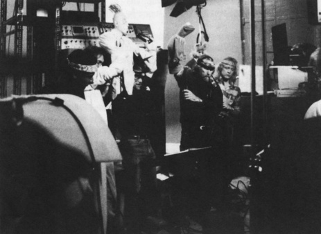 |
| Figure 1.1 Taping the Jim Henson Hour. Photo courtesy of Rex Grignon. |
Henson already had been doing some work with wireless telemetric robotics to animate characters for shots in which there was no way of controlling them directly, such as for a scene in The Muppet Movie in which Kermit is riding a bicycle and the audience sees the whole character in frame with his head moving around and singing a song. “It was a robot Kermit, and Jim had this foam Kermit head with some potentiometers on it that transmitted a radio signal to the robot on the bike,” says Rosendahl. That device, shown in Figure 1.2, was used for the Waldo C. Graphic character, with some modifications. PDI built a mechanical arm to record the position of the character in space. Instead of the radio link, the robot had a direct hardware link to one of PDI's Silicon Graphics systems. A control box with buttons allowed them to do eye blinks.
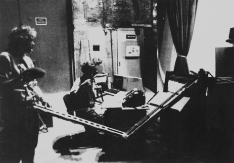 |
| Figure 1.2 Steve Whitmayer (L) and Rex Grignon operating the device used to control Waldo C. Graphic. Photo courtesy of Rex Grignon. |
“All the videotape recording was done in Toronto, so we moved all the equipment up there and basically got it to work live on the set,” says Rosendahl, “so that we took a feed of the video camera and then comped in Waldo on top of it, and that's what the performance would look like, even though the video was recording the final image without Waldo in there, but the performers would look at the one with the rough-version Waldo.”
Steve Whitmayer, who after Henson's death was in charge of bringing Kermit the Frog to life, was the puppeteer operating the device. “Essentially, it was a puppet, something that the puppeteer was familiar with at the end,” recalls Rex Grignon, Head of Character Animation at PDI/DreamWorks Animation. “He could put his hand in this and just fly it anywhere in the space within that region.” During the show, the puppeteer's motion data was read in and interpreted to control Waldo on the screen as a low-resolution version. “We modeled a 50-polygon version of Waldo,” says Grignon. “It was all within screen space. The puppeteers, when doing a normal puppet, would have their hand in the puppet, and they'd be looking down at a monitor, so they'd be able to gauge their performance, so they were absolutely used to this.” The new technique had the added benefit that the puppeteer could bring the puppet down and not worry about hiding from the camera.
Grignon was in charge of recording the motion. “As we started a performance I'd essentially start the system recording, do the blinks, and when the director said cut, I'd cut and I'd save that take in a similar language to what they were using on the show,” says Grignon. They kept track of the takes that Henson liked, because they needed to ensure that the data stayed in sync with the rest of the characters in the show. This was necessary so that after the editing of the show, PDI could use the data matching the chosen takes to produce the animation.
The device generated some interference, but although the character tended to jump and pop around, it looked pretty good for the live session. After the recording session, the data would be sent via phone line to the PDI studio, then located in Sunnyvale, California, and a PDI team would massage it to eliminate all the noise and add the necessary secondary animation, such as the belly wiggle. The team would also add several costume changes that required transitions, such as scenes in which the character turned into other objects (e.g., a book or an electric saw), and would render the final high-resolution character.
They were doing one episode a week with about 1min of the Waldo character. “We'd go up on the weekend, we'd shoot the show on Monday, we'd send the tape back on Tuesday, and then Michelle Choi, who was here, would basically render the tape. We'd come back, we'd all work on this for about 5 days rendering a minute of stuff and adding any extra props and extra animation,” recalls Grignon. “We lived here, we just lived here. We slept here every night.”
“I still think this is one of the best uses of motion capture,” notes Grignon, “You can take advantage of the puppeteer's skills, because these guys are masters. It's just amazing seeing them put their hand in a puppet and it just comes to life. I just remember Graham and I, both were just continually astounded with the subtleties that these guys could bring to these characters.”
Waldo C. Graphic was brought back to life by PDI in 1991 for the MuppetVision 3D movie, still being shown at Disney-MGM Studios in Orlando, Florida.
Exoskeleton
In 1988, PDI commissioned Rick Lazzarini's The Creature Shop to build a Waldo device for the upper body and head. They called this mechanical device an “exoskeleton”; it was based on optical potentiometers on each joint (see Figure 1.3). “It took us two passes to get one that really worked well,” recalls Carl Rosendahl. “Analog parts are too noisy,” notes Richard Chuang. The second version had digital parts.
 |
| Figure 1.3 Jamie Dixon wearing the PDI exoskeleton as Graham Walters makes adjustments during a shoot for Toys. Photo courtesy of PDI. |
The second exoskeleton was used for the Barry Levinson movie Toys, in a sequence for which PDI had to create an X-ray view of an ongoing meeting. “Jamie Dixon, who was our lead guy in the LA office, was the effects supervisor, and he actually was the one who did the performing,” says Rosendahl. “And because there were multiple characters, he actually did it in multiple passes.” Rosendahl also recalls that there were some glitches in the data that had to be cleaned up after the performance, but usable data was available in a reasonable amount of time. Toys was the first motion picture in which a digital character was successfully created using motion capture.
PDI later used a Flock of Birds, an electromagnetic device manufactured by Ascension Technology Corporation, on several projects in their Los Angeles office. One of them was a bit called “The Late Jackie Lenny” for a Comedy Central pilot in which a skeleton was a talk show host and would interview live comics or do a stand-up act.
For all the projects involving that device, PDI fabricated accessories to help hold the sensors in place and make the capture experience easier on the performer. Most of these were based on Velcro strips, but the head sensor was placed on top of a baseball cap so that when the performer took off the cap, the character would look like it had taken off its head. The device had some problems with interference. For example, the studio was located on the third floor of a three-story building, and the air conditioning equipment was located on the roof, right above the stage. When the air conditioning kicked on while the device was being used, the characters on screen would sway up and down.
deGraf/Wahrman
Brad deGraf also experimented with performance animation while working at Digital Productions, using Jim Henson's Waldo device. After Digital Productions was purchased by Omnibus, Brad left and joined forces with Michael Wahrman, also from Digital Productions, and founded deGraf/Wahrman Production Company.
In 1988, Silicon Graphics contracted the services of deGraf/Wahrman to create a demonstration piece for their new 4D models. The piece was an interactive animation called “Mike the Talking Head,” which was showcased at SIGGRAPH'88. For the first time, an animated character was able to interact with the audience. The controls that animated the character in real time were operated by a puppeteer during the conference. deGraf/Wahrman's proprietary software was used to create an interface between the controls and the rendering engine and to produce interpolated instances of the character's geometry. The new Silicon Graphics 4D workstation had the horsepower to render the character in real time.
When deGraf and Wahrman dissolved their partnership, Brad joined Colossal Pictures and started rewriting the performance animation software. In 1993, he developed “Moxy,” a character for the Cartoon Network that was operated in real time using an electromagnetic tracker. In 1994, he founded Protozoa, a spin-off from Colossal's performance animation studio. His focus has been on real-time performance animation solutions, including software and character development for different media, including television and the Web. ALIVE, Protozoa's proprietary performance animation software, supports multiple input devices, including motion capture systems, joysticks, and MIDI controllers. It also outputs to different formats, including live television and the World Wide Web via VRML (Virtual Reality Modeling Language).
Kleiser-Walczak Construction Company
In 1986, Jeff Kleiser began experimenting with motion capture while he was at Omnibus Computer Graphics. “We used the optical system from Motion Analysis in Santa Rosa, California, to encode martial arts movement for use in a test for Marvel Comics,” recalls Kleiser. “Results were disappointing due to the alpha code we were working with.”
In 1987, after Omnibus closed, Kleiser joined forces with Diana Walczak, who had been sculpting human bodies, and founded Kleiser-Walczak Construction Company. Their specialty would be to build and animate computer-generated actors, or Synthespians.
“After creating our first Synthespian, Nestor Sextone in 1988, we got together with Frank Vitz and went back to Motion Analysis to capture motion for our second digital actor, Dozo, in creating the film Don't Touch Me, in 1989,” says Kleiser. “We were only able to get about 30s of usable motion capture, and we had to recycle it to fill the 3.5min of the song we had written.” Vitz had been working with Robert Abel and Associates and had some motion capture experience, as he had been part of the team that created “Brilliance.”
Over the years, Kleiser-Walczak has created digital actors for special venue, commercial, and feature film projects. They created dancing water people for the Doug Trumbull stereoscopic ride “In Search of the Obelisk,” located inside the Luxor Hotel in Las Vegas. Using a Flock of Birds electromagnetic system by Ascension Technology Corporation, they also created digital stunt doubles for Sylvester Stallone, Rob Schneider, and others for the film Judge Dredd. In their most recent use of motion capture, Kleiser-Walczak produced “Trophomotion,” a commercial spot for Stardox athletic braces in which two basketball trophies come to life. They used a combination of keyframe animation and motion capture, which they achieved with an optical system manufactured by Adaptive Optics in Cambridge, Massachusetts.
Their latest project is computer imagery for “The Amazing Adventures of Spiderman,” a ride for Universal Studios' Islands of Adventure, in Orlando, Florida. “We tested mocap [motion capture] for this project, but it quickly became clear that superhero characters need to have super-human motion, and that keyframe animation gave us the look and flexibility we wanted,” says Kleiser. “All the animation in the project was therefore done with keyframe animation.”
Homer and Associates
In the early 1990s, projects utilizing motion capture in computer graphics were starting to become part of actual production work, so companies whose main business was based on this technology started to surface. Medialab, Mr. Film, Windlight Studios, SimGraphics, and Brad deGraf at Colossal Pictures concentrated their efforts on real-time applications that included character development and puppeteering, while Biovision, TSi, and Acclaim embraced the non-real-time technology for the up-and-coming video game market. At the same time, commercial production using the now traditional motion capture techniques was initiated by Homer and Associates.
Party Hardy
Although Homer and Associates had already created a shot for the film Lawnmower Man in 1991 using motion capture, they produced their initial entry in the advertising market in 1992: “Party Hardy,” a spot promoting the Pennsylvania Lottery. It consisted of an animated crowd of lottery tickets at a costume party. The spot was especially challenging because it had to have humanoid motion and facial expressions, and each ticket had to be different. There also had to be a feeling of interaction among the characters.
Peter Conn, president and founder of Homer and Associates, decided to use a camera-based system to collect the motions for the spot. The system used was an Elite Motion Analyzer, a system manufactured by Bioengineering Technology Systems (BTS) in Italy primarily for medical and industrial applications, and provided by SuperFluo, a company dedicated to bringing these medical systems to the entertainment industry. SuperFluo added custom software geared to computer animation to the already existing configuration.
The spot was directed by Michael Kory, who also performed the motions for all the characters. For the body motions, markers were placed on human-size foam rectangles, shown in Figure 1.4, which Kory held while acting. The facial motions were also performed by Kory using the Elite system, but this time using smaller markers placed in specific areas of his face. The captured facial motion was used to help interpolate between facial shapes that were built by Kory.
 |
| Figure 1.4 The Homer & Associates team with the BTS motion capture system for the Pennsylvania Lottery commercial “Party Hardy”: (left to right) Michael Kory, director (behind foam); Peter Conn, Producer; Francesco Chiarini (SuperFluo, motion capture specialist); Umberto Lazzari (SuperFluo, motion capture specialist); John Adamczyk, technical director. |
“Party Hardy” is a good example of a project in which motion capture was used to collect data from an object or character puppeteered by a performer, as opposed to data collected from the actual performer's body.
Steam
Peter Gabriel's music video “Steam” was a coproduction between Colossal Pictures and Homer and Associates. The video was produced in 1992 and was directed by Stephen Johnson, director of other award-winning Peter Gabriel videos, including “Big Time.”
“There was a period of several months when we were actively working with Brad deGraf and Stephen Johnson,” recalls Peter Conn, president of Homer and Associates. “He [Stephen Johnson] had a fertile imagination and an equally formidable lack of decisiveness and reality orientation. I remember that every meeting we had about what the video would include always involved going through dozens of storyboards of very elaborate effects. Although the beginning of the song was precisely worked out bar by bar, we never ever got through even half the song. There were dozens of elaborate concepts, which he seemed to want in the video. Since he was having an inability to downsize the scope, he would fly to London or Senegal to get Peter's input. When he came back, there was never any consensus, just more and more concepts and ideas. A lot would have been almost achievable had the months of prep been actual production, but by the time the video was officially green-lighted there was no more than 4 weeks or so left to do everything. Motion capture was always specified as the great technique that would somehow make it all possible.”
The motions would be collected using the same BTS optical system used on “Party Hardy.” “By the time Peter Gabriel showed up for the motion capture sessions, the SuperFluo guys, Umberto Lazzari and Francesco Chiarini, had set up in our usual place, the large abandoned white storage room in the basement of the adjacent building,” says Conn.
They spent 2 days capturing motion data from Peter Gabriel and a dancer. About 150 different movements were collected. “Peter had one rule for the room: no spectators,” recalls Conn. “When the playback rolled, everyone had to dance and get into the music. He liked so much doing the motion samplings that he refused to quit. Knowing that we had only time left to animate a few scenes, it was way over the top, but hey, it was Peter Gabriel and we were getting data.”
In the end, there were only a couple of shots in which captured motion data was used. The longest shot was one in which Peter was supposed to be made of ice, with dancing fire girls alongside. “He was to melt then re-emerge as water,” says Conn. Michael Kory animated the scene and Scott Kilburn wrote the particle software, which was based on Homer's proprietary code that had been written by John Adamczyk for Lawnmower Man.
A crew of eight undertook the task of putting together the shots in a short period of time, while the director was in London. “Memorable moments included a conference call after they had seen a test over in the UK,” says Conn. “Stephen was upset because he said that he had wanted the girls ‘not on fire’ but ‘of fire.’ We didn't really know what he meant, but we kept adding more particles. Then after the scene was delivered, he was still upset. It turned out that the girls weren't voluptuous enough, so we took the models and pulled the breasts out an ungodly much and then rendered just some breast fire and comped it on.”
The other scene with captured motion data was the “Garden of Eden,” in which both Gabriel and the dancer turn into digital characters after walking through an imaginary plane. “Actually, Brad [deGraf] did a great mocap piece with Peter Gabriel as a puppet but for some reason it never made the final cut,” recalls Conn. “Despite the multitudinous mistakes and us knowing what it could have been given more time, the video went on to win some major awards, like the Grammy for Video of the Year in 1993,” he notes.
Other notable motion capture works involving Homer and Associates include shots from the film Lawnmower Man and music videos such as Vince Neil's “Sister of Pain” and TLC's “Waterfalls,” produced for Atomix with motion data from TSi, my former company. This was my first collaboration with Homer and Associates and Atomix.
Motion Capture Service Bureaus
In the early 1990s, a few companies started offering motion capture services to other production companies. The early players were Biovision in San Francisco and TSi in Los Angeles and San Francisco. The systems used were optical and the software to solve the motion data was all proprietary, because the few companies that sold optical motion capture equipment didn't have biomechanical solvers that could deliver data useable for animation to any of the current 3D animation software programs. Entertainment was a brand new market for them as they have been servicing mostly the Life Sciences sector at that time, so they looked at the service bureaus to help them access the market.
Owning and operating an optical system at the time was not only very expensive, but extremely technical and not user friendly by any means. The data was very difficult to collect and there was always a risk that the final data would be unusable. Verifying the data during the shoot wasn't possible as it took a very long time to process. Initially, at TSi we had mostly clients in the video gaming industry. Video game consoles were becoming more powerful and could render more complex motions, so most game developers started using motion capture when service bureaus started doing business. We were servicing clients from all over the world for a few years until motion capture systems became more user friendly. In 1997, TSi sold their biomechanical solver and animation software plug-ins to Motion Analysis Corporation. Optical systems started including the necessary software to produce performance animation and other service bureaus started opening in many countries. Also, larger video game developers such as Electronic Arts started acquiring systems to produce in-house graphics. Today it is a given that any video game that has human characters is expected to have used motion capture to generate the performance data.
Types of Motion Capture
Human motion capture systems are classified as outside-in, inside-out, and inside-in systems. These names are indicative of where the capture sources and sensors are placed.
• An outside-in system uses external sensors to collect data from sources placed on the body. Examples of such systems are camera-based tracking devices, in which the cameras are the sensors and the reflective markers are the sources.
• Inside-out systems have sensors placed on the body that collect external sources. Electromagnetic systems, whose sensors move in an externally generated electromagnetic field, are examples of inside-out systems.
• Inside-in systems have their sources and sensors placed on the body. Examples of these devices are electromechanical or inertial suits, in which the sensors are potentiometers, powered goniometers or accelerometers and gyroscopes, and the sources are the actual joints inside the body.
The principal technologies used today that represent these categories are optical, electromagnetic, and inertial human tracking systems.
Optical Motion Capture Systems
Optical motion capture is a very accurate method of capturing certain motions when using a state-of-the-art system. It is not a real-time process in most cases; immediate feedback is not possible on the target character unless motions are not too complex and there aren't too many performers. Data acquired optically can require extensive postprocessing to become usable, so operating costs can be high.
A typical optical motion capture system is based on a single computer that controls the input of several digital CCD (charge-coupled device) cameras. CCDs are light-sensitive devices that use an array of photoelectric cells (also called pixels) to capture light, and then measure the intensity of the light for each of the cells, creating a digital representation of the image. A CCD camera contains an array of pixels that can vary in resolution from as low as 128 × 128 to as high as millions of pixels. The state of the art today is 16 million pixels (megapixels), but that number will continue to increase every year.
Obviously, the higher the resolution, the better, but there are other trade-offs. The samples-per-second rate, or frame rate, has to be fast enough for capturing the nuances of very fast motions. In most cases, 60 samples per second are more than enough, but if the motions are very fast, such as a baseball pitch, a lot more samples per second are required. By today's standards, a CCD camera with a resolution of 16 megapixels would be able to produce up to 120 samples per second at that resolution. To capture faster motions, the resolution has to be dropped. Another important feature is shutter synchronization, by which the camera's shutter speed can be synchronized with external sources, such as the light-emitting diodes (LEDs) with which optical motion capture cameras are usually outfitted.
Some of the most modern cameras process the imagery locally before sending it to the computer, saving broadband and processing time of huge amounts of data. This can be very useful, especially when the system has a large number of ultra-high-resolution cameras, each capturing hundreds of images per second.
The number of cameras employed is usually no less than 8 and no more than 32, but there are cases where hundreds of cameras are used as I will explain later. They capture the position of reflective markers at speeds anywhere between 30 and 2000 samples per second. The cameras are normally fitted with their own light sources that create a directional reflection from the markers, which are generally spheres covered with a material such as Scotch-Brite tape. Red light sources are preferred because they create less visual distortion for the user. Infrared is also used but it is slightly less effective than visible red. The marker spheres can vary from a few millimeters in diameter, for facial and small-area captures, to a couple of inches. The Vicon system, shown in Figure 1.5, is an example of a state-of-the-art optical system that can accommodate up to hundreds of cameras.
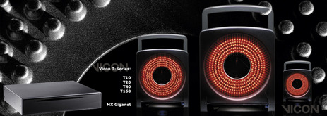 |
| Figure 1.5 The Vicon MX optical motion capture system. Photo courtesy of Vicon Motion Systems. |
Most optical systems were designed and manufactured for medical applications; as such, they lacked many features that are important to computer graphics applications. The Vicon 8 system was the first system designed with computer graphics in mind. It was the first able to support SMPTE time code, a time stamp used by most film and television applications. Even if you videotaped your capture session, there was no easy way to match the video to the actual motion data. Having time code in the motion data allows you to edit the motion files, as you would do with live-action video, and properly plan the association of the characters with background plates. Another very useful feature that the Vicon 8 introduced was the fact that reference video of the session could be synchronized, or genlocked, with the actual data collection. In addition to video genlock, the Vicon 8 software could shoot AVI movie files at the same time as it captured. These movie files are great reference for data postprocessing and application.
The optical system must be calibrated by having all the cameras track an object with known dimensions that the software can recognize, such as a cube or a wand with reflective markers. By combining the views from all cameras with the known dimensions of the object, the exact position of each camera in space can be calculated. If a camera is bumped even slightly, a new calibration must be performed. It is a good idea to recalibrate the system many times during a capture shoot, since any kind of motion or vibration can shift the position of a camera, especially if the studio is located on unstable ground.
At least two calibrated views are needed to track a single point's 3D position, and extra cameras are necessary to maintain a direct line of sight from at least two cameras to every marker. That doesn't mean that more cameras are better, because each additional camera increases postprocessing time. There are other methods for minimizing occlusions that are implemented in software and used during postprocessing. The most time- and cost-effective solution is different for every case, depending on the type, speed, and length of the motion, as well as on the volume of capture and the available light. Figure 1.6 shows a performance being filmed on an optical motion capture stage.
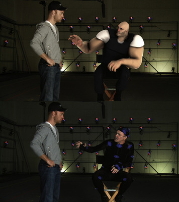 |
| Figure 1.6 A performance in an optical motion capture stage. Photo courtesy of House of Moves. |
Once the camera views are digitized into the computer, it is time for the postprocessing to begin. The first step is for the software to try to produce a clean playback of only the markers. Different image processing methods are used to minimize the noise and isolate the markers, separating them from the rest of the environment. The most basic approach is to separate all the groups of pixels that exceed a predetermined luminosity threshold. If the software is intelligent enough, it will use adjacent frames to help solve any particular frame. The system operator has control over many variables that will help in this process, such as specifying the minimum and maximum lines expected per marker, so the software can ignore anything smaller or bigger than these values.
The second step is to determine the 2D coordinates of each marker for each camera view. This data will later be used in combination with the camera coordinates and the rest of the camera views to obtain the 3D coordinates of each marker. The third step is to actually identify each marker throughout a sequence. This stage requires the most operator assistance, since the initial assignment of each marker has to be recorded manually. After this assignment, the software tries to resolve the rest of the sequence until it loses track of a marker due to occlusion or crossover, at which point the operator must reassign the markers in question and continue the computation. This process continues until the whole sequence is resolved and a file containing positional data for all markers is saved.
The file produced by this process contains a sequence of marker global positions over time, which means that only each marker's Cartesian (x, y, and z) coordinates are listed per frame and no hierarchy or limb rotations are included. It is possible to use this file for computer animation, but a more extensive setup is required inside the animation software in order to resolve the final deformation skeleton to be used. Experienced technical directors can benefit by using this file's data, because it allows more control over what can be done in a character setup. For the average user, however, the data should be processed further, at least to the point of including a skeletal hierarchy with limb rotations. Most optical systems include data-editing systems that allow the user to produce the rotational hierarchical data before importing it to animation software. Figure 1.7 shows a sample screen of the Vicon Blade integrated motion capture platform that is shipped with the Vicon MX optical motion capture system.
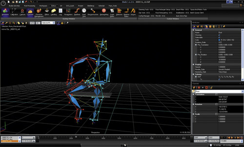 |
| Figure 1.7 Vicon Blade motion capture software. Photo courtesy of Vicon Motion Systems. |
Advantages of Optical Systems
• Optical data can be extremely accurate.
• A larger number of markers can be tracked.
• It is easy to change marker configurations.
• It is possible to obtain approximations to internal skeletons by using groups of markers.
• Performers are not constrained by cables.
• Optical systems allow for a larger performance area than most other systems today.
• Optical systems have a higher sample rate of capture, resulting in more measurements per second.
Disadvantages of Optical Systems
• Optical data requires extensive postprocessing, so operating costs are high.
• Hardware is expensive. An entry-level optical system can cost over $50,000 and a high-end system can cost over a million.
• Optical systems cannot capture motions when markers are occluded for a long period of time.
• Capture must be carried out in a controlled environment, away from yellow light and reflective noise.
Radio Frequency Positioning Systems
For the past couple of decades, there have been no major changes in the way motion capture is done. Since the late 1980s, optical has been the preferred method in the entertainment and life sciences fields, as accuracy is more necessary than real-time measurement.
Technological advances in hardware since optical systems emerged have been mostly in camera count and camera resolution. Meanwhile, other technologies have remained stagnant in their advances. Software improvements have been mostly in finding clever ways to obtain somewhat real-time feedback and better ways of using and managing data.
Radio frequency (RF) is the new emerging technology in position tracking. Not to be confused with using RF to deliver data wirelessly, but rather using RF to calculate position measurement. Currently, there are several types of RF-based systems, but none of them has the accuracy needed for performance capture. However, it is clear that this will be the next state of the art in motion capture.
Global Positioning System (GPS)
The best example of RF positioning that has been around for a while is GPS. GPS was originally developed by the US Department of Defense in the 1970s as a tool to aid in the location of ballistic missile submarines, because it is necessary to know the exact location of the submarine at the time of launch in order to make sure the missile hits its target. The first GPS satellite was launched in 1978 and the full constellation was completed in 1995. In 1983, President Reagan made GPS available for nonmilitary use after Soviet fighter jets shot down Korean Air flight 007, a passenger jet that had accidentally entered Soviet airspace, killing everyone on board. The nonmilitary version of GPS was made intentionally less accurate by the US government until the year 2000, when it stopped distorting signals for security reasons. As a result, civilian uses of GPS started to flourish and demand has kept increasing. It is estimated that the worldwide civilian market for GPS devices will reach $75 billion by 2013.
The United States' GPS constellation consists of 24 satellites that travel in a very precise orbit at 12,000 miles above the earth. They complete a full cycle around the globe in about 12h. The system is designed so that at least five satellites have a simultaneous view of any point on the surface of the earth. GPS units receive the signals of the satellites and use them to compute their location relative to a coordinate system. The coordinate system varies by manufacturer, but it is usually based on longitude/latitude like DMS (Degree/Minute/Second) or some decimal version of that. At least four satellites are required to make the position calculation.
Some GPS satellites have been around for a couple of decades and are already due for replacement. Meanwhile, the European Union is due to launch its own version of a satellite navigation system called Galileo in 2013.
Today, GPS can be found in vehicles, mobile phones, computers, shipping containers, wristwatches, dogs, and even troops in the battlefield. It isn't accurate enough or has enough samples per second to use as a motion capture tool, but other systems based on similar technology could achieve the accuracy and frequency required if they could be localized. In other words, instead of satellites sending signals through the atmosphere, it would use local transmitters in a contained environment and receivers placed on the subject.
Real-Time Location Systems (RTLS)
RTLS were originally conceived as an addition to RFID technology. RFID is an electronic replacement of barcode to be used as an asset tracking and inventory device. The idea was that in addition to having the information that the RFID chips contain, the exact position within the warehouse or retail facility would also be available.
RFID hasn't caught up in the market as fast as it was originally estimated, but RTLS proved to be a valuable technology in its own right. Today, RTLS encompasses a large percentage of the total RFID business and is growing fast. There are many types of RTLS but the most popular is the scheme based on wireless Internet (WiFi), as it can use existing WiFi deployments, so it is fairly cost effective. Other types of RTLS schemes include ultra-wideband (UWB), UHF, GPS, GSM, and even ultrasound.
RTLS is not meant to be exact. Most systems have accuracies of around a meter, so it isn't well suited for motion capture. Its main applications are in tracking assets. Hospitals are one of the largest users of RTLS as there's a lot of portable equipment moving around and most of it is quite expensive.
As RTLS technology evolves, it may become viable for motion capture applications; however, the current markets are so large and undeveloped, that it isn't a priority to exploit the entertainment market as of yet.
Local Positioning System
Local positioning systems (LPS) are still in their infancy and not in use yet. These are systems that use RF to measure highly accurate positioning data at a very large sample rate. These systems will be viable for motion capture applications and will most likely become the state of the art in this field in the next few years.
I have spent most of my last few years working on the development of the first LPS system. Most RF positioning systems (GPS, RTLS) obtain their measurements by calculating the time it takes for signals to travel from a transmitter to a receiver. The speeds of these signals are so high that the accuracy needed for motion capture cannot be achieved, even if the signals are sent back to a transceiver. The most difficult problem to solve is in using the signals in a smart way to achieve the accuracy needed.
The LPS system that I've been working on already is capable of achieving measurement accuracy comparable to that of optical systems (1–2mm). It still needs further development in order to be useable in production, such as miniaturization and automatic calibration, but the main point is that we now know that this is viable technology that will eventually become the motion capture standard.
LPS systems are similar to GPS, but work in an inverse way. The difference is that the object captured sends signals as opposed to receiving them. There is an array of antennas around the area to be captured. The moving objects are fitted with small transmitters that send hundreds of bursts per second. The antennas receive the signals and send them to a signal processing unit, which calculates the position, using the known location of each antenna, the signal travel time, and some additional characteristics of the signal in order to achieve the accuracy needed.
The current system is already capable of calculating the position measurements of up to 32 transmitters or tags 250 times per second. The system is capable of working in an area of about 25,000m3, which is about 20 times larger than the current capture volume of a typical optical system.
Figure 1.8 shows the tags and antennas developed for the Menache LPS prototype system.
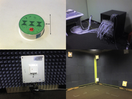 |
| Figure 1.8 Menache LPS prototype. |
The most interesting part of LPS systems is their ability to develop new markets and applications. Besides improving on the current uses in performance capture and life sciences research, LPS could enable the following applications:
• Sports—LPS systems could be used to generate sports analysis data and injury diagnosis at the actual time of the sporting event as opposed to the way it is done now, which is in a contained laboratory. Also, broadcast replay and analysis graphics could be generated in real time and used to aid in the chronicle of a sporting event. Figure 1.9 shows an example use of LPS in a soccer field. The proposed system would include 16 antennas placed around the stadium and a single tag on each player. In the future, multiple tags could be used and an accurate render of the event could also be produced.
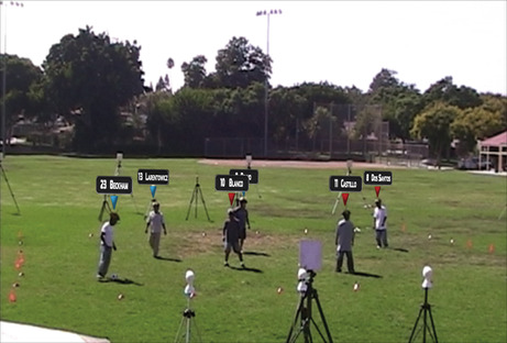 |
| Figure 1.9 An example of the use of an LPS system in a soccer match broadcast. |
• Healthcare—Some of the applications of LPS in healthcare are very interesting. Imagine being able to align or correct imagery for patient movement during an imaging session or even during surgery.
• Gaming—LPS systems could enable a new level of virtual reality that could be used at the arcade and at the consumer level. Since hardware could be inexpensive to manufacture in large volumes, an input device for home gaming devices could be developed. Also, location-based games such as Laser Tag could be transformed into a new kind of virtual or augmented reality experience.
Advantages of LPS Systems
• Tags transmit an ID pattern so no post identification is required.
• LPS systems calculate all accurate measurements in real time.
• LPS capture volumes are only limited by computing power.
• LPS can work outdoors as well as indoors.
• LPS tags can be worn under clothing.
• LPS systems will be cheaper to operate, as no postprocessing will be necessary.
• LPS systems will be cheaper to manufacture as no optical components are required.
• Automatic calibration will make these systems more portable and useable on film sets.
• LPS will be able to capture thousands of tags in real time.
Disadvantages of LPS systems
• LPS signals do not travel through metallic surfaces.
• Potential for RF interference. In its initial stages, LPS systems will require a characterization of the capture volume prior to use. Systems will be able to work using different frequencies to avoid this problem.
Electromagnetic Trackers
Electromagnetic motion capture systems are part of the six degrees of freedom electromagnetic measurement systems' family and consist of an array of receivers that measure their spatial relationship to a nearby transmitter. These receivers or sensors are placed on the body and are connected to an electronic control unit, in most cases by individual cables.
Also called magnetic trackers, these systems emerged from the technology used in military aircraft for helmet-mounted displays (HMDs). With HMDs, a pilot can acquire a target by locating it visually through a reticule located on the visor. A sensor on the helmet is used to track the pilot's head position and orientation.
A typical magnetic tracker consists of a transmitter, 11–18 sensors, an electronic control unit, and software. A state-of-the-art magnetic tracker can have up to 90 sensors and is capable of capturing up to 144 samples per second. The cost ranges from $5000 to $150,000, considerably less than optical systems.
The transmitter generates a low-frequency electromagnetic field that is detected by the receivers and input into an electronic control unit, where it is filtered and amplified. Then, it is sent to a central computer, where the software resolves each sensor's position in x, y, and z Cartesian coordinates and orientation (yaw, pitch, and roll).
Magnetic trackers such as the Flock of Birds by Ascension Technology Corporation use direct current (DC) electromagnetic fields, whereas others, such as the Polhemus Fastrak, use alternating current (AC) fields. Both these technologies have different problems associated with metallic conductivity. AC trackers are very sensitive to aluminum, copper, and carbon steel, but not as sensitive to stainless steel or iron, whereas DC trackers have problems with ferrous metals, such as iron, but not with aluminum and copper.
Many of these conductivity problems are caused by the induction of a current in the metal that creates a new electromagnetic field that interferes with the original field emitted by the tracker. These new fields are called eddy currents. Some magnetic trackers use special algorithms to compensate for these distortions by mapping the capture area, but these calibrations only work with static, predefined problem areas such as metallic structures in buildings. In most cases, it is better to avoid any high-conductivity metals near the capture area. This limitation makes the magnetic tracker difficult to transport to different stages or sets.
The latest use of magnetic systems is in consumer video gaming. Sixense Entertainment, a Los Gatos, CA–based company, is developing a wireless gaming controller (Figure 1.10) based on a low-power AC field that will be compatible with computer and console video games. Devices such as these will take the performance gaming trend started by the Nintendo Wii to the next level.
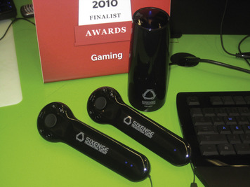 |
| Figure 1.10 Sixense Truemotion Input Device. Photo courtesy of Sixense. |
Magnetic trackers in the entertainment industry are used mostly for real-time applications such as live television, live performances, and location-based or Internet virtual reality implementations. Sometimes, they are used as part of puppeteering devices. A performer can author the body motions of a character with the magnetic tracker while someone else is performing the facial expressions and lip syncing using a face tracker or a data glove. At the same time, a puppeteer can be animating the character's eyes using a simple mouse. They are also used to obtain global positioning for other systems, such as inertial motion capture suits.
Advantages of Magnetic Trackers
• Real-time data output can provide immediate feedback.
• Position and orientation data is available without postprocessing.
• Magnetic trackers are less expensive than optical systems, costing between $5000 and $150,000.
• The sensors are never occluded.
• It is possible to capture multiple performers interacting simultaneously with multiple setups.
Disadvantages of Magnetic Trackers
• The tracker's sensitivity to metal can result in irregular output.
• Performers are constrained by cables in some cases.
• Magnetic trackers have a lower sampling rate than some optical or LPS systems.
• The capture area is smaller than is possible with other systems.
• It is difficult to change marker configurations.
Electromechanical Performance Capture Suits
Electromechanical performance capture suits have been around for a while. They are inside-in systems based on a group of structures linked by potentiometers, gyroscopes, or similar angular measurement devices located at the major human joint locations. The newer versions use MEMS (Microelectromechanical Systems) inertial sensors placed over a Lycra or spandex suit. The idea is that the suit measures all human limb rotations.
Potentiometers are components that have been used for many years in the electronics industry, in applications such as volume controls on old radios. A slider moving along a resistor element in the potentiometer produces a variable voltage-potential reading, depending on what percentage of the total resistance is applied to the input voltage.
MEMS inertial sensors are also angular measurement devices, but they are much smaller and more accurate. They are basically integrated circuits combined with micromachined moving parts. Good examples of devices that use MEMS technology are the Nintendo Wii input device and the iPhone.
One big drawback of performance capture suits is their inability to measure global translations. In most cases, an electromagnetic or ultrasound sensor is added to the configuration to solve this problem, but that subjects the setup to the same disadvantages as the electromagnetic or ultrasonic systems, such as sensitivity to nearby metals or bad accuracy and drift. In addition, the design of most of these devices is based on the assumption that most human bones are connected by simple hinge joints, so they don't account for nonstandard rotations that are common to human joints, such as in the shoulder complex or the lower arm. Of course, this can actually be a benefit if the mechanical setup of a particular digital character calls for such types of constraints.
A good example of a performance capture suit is the Xsens MVN, shown in Figure 1.11. This suit uses inertial sensors based on MEMS technology.
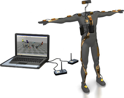 |
| Figure 1.11 The MVN Inertial Suit by Xsens. Photo courtesy of Xsens Technologies. |
Advantages of Electromechanical Body Suits
• The range of capture can be very large.
• Electromechanical suits are less expensive than optical and magnetic systems.
• The suit is portable.
• Real-time data collection is possible.
• Data is inexpensive to capture.
• The sensors are never occluded.
• It is possible to capture multiple performers simultaneously with multiple setups.
Disadvantages of Electromechanical Body Suits
• The systems have a low sampling rate.
• They can be obtrusive due to the amount of hardware.
• The systems apply constraints on human joints.
• The configuration of sensors is fixed.
• Most systems do not calculate global translations.
Digital Armatures
Digital armatures can be classified into two types: (1) keyframing or stop-motion armatures and (2) real-time or puppeteering armatures. Like the mechanical suit, both types consist of a series of rigid modules connected by joints whose rotations are measured by potentiometers or angular sensors. The sensors are usually analog devices, but they are called digital because the resulting readings are converted to digital signals to be processed by the computer system. These armatures are typically modular in order to accommodate different character designs.
Keyframing armatures were initially used to help stop-motion animators animate digital characters; they are not really considered motion capture systems because they are not driven by a live performer. I mention them because most commercially available armatures can also be used as real-time armatures. Some proprietary armatures are dual purpose such as a device initially called the Dinosaur Input Device (DID), which was devised by Craig Hayes at Tippett Studio in Berkeley, California. The name was conceived because this unit was used to animate some of the digital dinosaurs in Jurassic Park. Later, the device was used to animate the bugs in Starship Troopers and it was called the Digital Input Device (Figure 1.12).
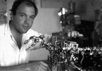 |
| Figure 1.12 Digital Input Device (D.I.D) designer Craig Hayes and the Raptor D.I.D. puppet. Jurassic Park 1992-1993. Photo courtesy of Tippett Studio. |
The basic concept behind keyframing armatures is that the animator poses the device manually to generate each keyframe in the animation. The character in the animation software is set up with a mechanical structure equivalent to the armature's. By pressing a key, the animator uses the computer to record the armature's pose into the digital character for a particular frame in time. This is done via a driver program that connects the device, typically plugged in to a serial port, to the animation software. Once all the key poses are recorded, the software treats them as regular keyframes that might have been created with the software by itself.
Puppeteering armatures are very similar to keyframing armatures, except the motion is captured in real time as performed by one or more puppeteers. An example of such a setup is the proprietary armature developed by Boss Film Studios to capture the motion of Sil, the alien character that H.R. Giger designed for the film Species.
Digital armatures are not very popular any more. The last commercially available example of a digital armature was the Monkey 2 by Digital Image Design in New York City (Figure 1.13). This unit could be used as both a keyframe and real-time armature. It was modular, so it could be assembled in different joint configurations. The first-generation Monkey had a fixed configuration, which made it unusable for any nonhumanoid applications. The typical cost for a 39-joint Monkey 2 setup was approximately $15,000, which included all the necessary parts as well as driver software for most well-known animation packages.
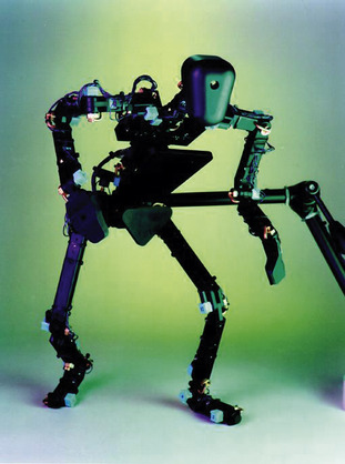 |
| Figure 1.13 The Monkey 2 armature. Photo courtesy of Digital Image Design. |
Facial Motion Capture Systems
There are several mechanical and optical devices for capturing facial motion. The most popular are the real-time optical face trackers, consisting of a camera that is placed in a structure attached to the performer's head so that it moves with the performer. The device captures the motion of small markers placed in different areas of the face. Unfortunately, these are 2D devices that cannot capture certain motions such as puckering of the lips, so the data is all in one plane and not very realistic. Three-dimensional facial motion data can be captured with an optical system using two or more cameras, yielding a much better result, but not in real time.
There are also newer optical systems that don't require markers, but are based on optical flow analysis. Such a system was used for the facial performance capture for the film Avatar.
The state of the art in facial motion capture is based on a combination of optical capture and software algorithms. The three major types of modern software algorithms to process facial optical data are muscle/skin simulators, dynamic blend shape solvers, and photogrammetry builders. There can also be combinations of two or three of these techniques. Most such algorithms exist as proprietary developments of visual effects companies, such as the muscle simulation software Sony Pictures Imageworks developed for films like The Polar Express or the dynamic blend shape solver used for Avatar, developed by Weta in New Zealand.
Facial Muscle and Skin Simulators
Facial muscle and skin simulators are algorithms that take optical data of the face and use it to solve facial poses based on anatomical rules and restrictions. This is a very good method to animate human faces, as it is based on real anatomy.
Initially, a model of the animated performer's face is built. The internal structure of the skull, jaw, and major facial muscles is also defined. It is ideal to have an MRI or a similar imagery of the performer to determine the exact location of the jaw. Most of the time, it is impossible to get such imagery, so the performer is asked to capture a series of expressions that are used to determine the muscle positions, movement, and jaw joint. We call this a training set.
The training set is used by the software to define what each muscle can and cannot do. The skull model serves as a collision object. The performance data is processed based on these restrictions, taking into account the dynamics of the skin.
Once the performance data is processed, the resulting stream is a series of normalized values per muscle. This means that a muscle in its relaxed state will have a value of zero, fully extended will have a value of one, and fully compressed minus one. The greatest benefit of using such a system is that it is extremely easy to apply this data to different human faces with different muscle layouts or limits.
Dynamic Blend Shapes
Blend shapes are probably the most popular method for animating facial performances. The method entails building a series of models of the character's face in different expressions and phonemes, which are the various mouth poses used for speech. The animator uses sliders to blend these expressions and create a facial pose.
Depending on the number of poses, this method can be very expensive to set up. The benefit is that it can be used to animate any kind of character, including humans.
It is possible to drive these blend shapes using facial motion capture data. The process starts with deciding on a list of shapes. These can be divided by phonemes, emotions, areas of the face, etc. There are a few popular lists of expressions that may work better depending on the nature of the character. A well-known system to categorize facial expressions is the Facial Action Coding System or FACS. The FACS research was first published in 1978 by Paul Ekman and Wallace Friesen, and it is widely used in the field of psychology to help in the interpretation of emotions. The list of shapes for a human face could be a combination of FACS units and phonemes.
Once the list is defined, it is necessary to capture the corresponding data. Each of the facial expressions in the list needs to be associated with a real expression from the performer, so regardless of the method used for facial motion capture, a dataset with every one of the expressions in the list needs to be created. This is similar to the training set used for facial muscle and skin simulation. Also, the corresponding digital model for each of the expressions needs to exist, and this is where the method can get really expensive.
Once all the assets are in place, there needs to be an algorithm that will convert an actual performance into a stream of shapes. The algorithm has to find the best fit of shape combinations; that is, the combination of blend shapes that will look closest to the performer's expression at that point in time. This algorithm can be a brute-force recursive algorithm or one of a few existing “approximation algorithms” that already can solve the “best fit” problem, such as the “least squares” method or “Kalman filtering.”
Obviously, the more expressions and models are predefined, the better is the end result.
Computer Vision
Photogrammetry is the method of building geometry based on photographic images. It has been around for a long time and has been used for many applications. The first application of photogrammetry in 3D animation was to create computer models that would be animated later in some other way. Capturing facial motion using photogrammetry is a relatively new application, as it requires significant computing power. It is called videogrammetry because it uses a set of video images instead of photographs. Further developments are labeled as computer vision methods, as they not only use the discrete video images, but also an analysis of their changes frame after frame to achieve the optimal result.
The idea is that a model is created dynamically for each frame of the performance. This model is used directly as the animated face or to extract data to drive another character model.
There are a few companies that specialize in computer vision facial performance capture. The leading ones are US-based Mova and UK-based Image Metrics. Some films that have ventured into the use of this technique are The Incredible Hulk and The Curious Case of Benjamin Button. Figure 1.14 shows Mova's array of special fluorescent lights and synchronized cameras.
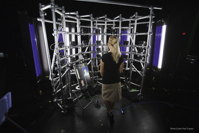 |
| Figure 1.14 Mova's array of special fluorescent lights and synchronized cameras. Photo courtesy of Mova. |
Other Motion Capture Systems
The Waldo
The Waldo is a telemetric device that imitates the motions of whatever it is controlling. It was named after Waldo Farthingwaite Jones, a fictional disabled scientist in Robert A. Heinlein's 1942 short story “Waldo” who invents a device that allows him to act beyond his biomechanical possibilities. Telemetry is by definition the transmission of measurements; consequently, the Waldo transmits measurements of the motion of joints and other body parts to a mimicking device. There are many kinds of Waldos, controlled by different body parts, such as the head, arms, or legs, or even the body as a whole. Their main applications in entertainment are the control of digital or animatronic characters.
The name “Waldo” is rumored to have been first used at NASA to name an early telemetry device, and it was used for years as a generic name for such machines. It is a trademark of The Character Shop, a company that specializes in animatronic characters. Figure 1.15 shows different kinds of Waldos manufactured by The Character Shop. The Jim Henson Creature Shop uses a device of this genre called the Henson Performance Control System to bring their animatronic or digital creatures to life.
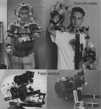 |
| Figure 1.15 Different types of Waldos manufactured by The Character Shop. Photos courtesy of The Character Shop. |
Hand Trackers
To capture the motion of small body parts, specialized trackers are needed because full-body tracking devices lack the necessary resolution. For example, it is practically impossible to track facial movements and movement of fingers with an electromagnetic tracker because the sensors are bigger than the locations where they need to be placed. It is possible to handle such situations with optical trackers in some cases.
For hand motions, there are several types of gloves that have small form-factor technologies, such as the very expensive Cyberglove II or the more reasonable 5DT Data Glove. One of the first commercially available hand trackers was the VPL DataGlove, shown in Figure 1.16, which was released in 1987. It was manufactured by VPL Research, a company founded by Jaron Lanier, a pioneer in the field of virtual reality, but the company ran into financial trouble and its technical assets and patents were acquired by Sun Microsystems in February 1998. The glove was based on fiber-optic sensors placed along the back of the fingers. As fingers rotated, the fibers were bent and their transmitted light was attenuated. The strength of the light was turned into a signal that could be measured by the processor to calculate the rotation of the fingers. Most DataGlove models had 10 sensors that measured the rotations of each of the two upper joints of the fingers. Some versions also had measurements for abduction (the angle between adjacent fingers). It could measure a minimum of 1° at up to 60 samples per second. The average cost was $8000.
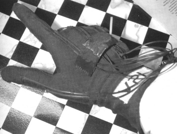 |
| Figure 1.16 The VPL DataGlove. Photo courtesy of Zak Zaidman. |
Another historically significant hand tracker was the Mattel PowerGlove, introduced in 1989 as an add-on controller for the Nintendo Entertainment System. It was conceived at VPL Research as a low-cost alternative to the DataGlove, called Z-Glove. VPL Research licensed it to Abrams Gentile Entertainment (AGE), the company that manufactured it for Mattel. The PowerGlove sold for about $100.
The difference that made the PowerGlove's cost so much lower than the DataGlove's was in the components. The optic fibers were replaced with less expensive conductive ink that was used as a resistor whose impedance variations indicated degrees of flexion. The global position and orientation were measured via ultrasonic pulses that were emitted from a few locations on the glove. The time taken for these pulses to reach the receivers was used to calculate in a very loose way the position and orientation of the glove. In fact, the glove emitters always had to be pointing at the receivers, which limited its range of motion. The PowerGlove only measured flexion of the thumb and three fingers, at a much lower resolution than the DataGlove.
The PowerGlove was a commercial failure, but it eventually became very popular as an inexpensive virtual reality input device. Since it was conceived as a peripheral device for the Nintendo game console, it had no standard interface. Thus, there was no easy way to connect it to anything else. When the popularity of the device became apparent, interfaces to use it with an IBM-compatible PC or an Apple Macintosh started to surface, either released by AGE, third-party manufacturers, or people experimenting with the device.
The Cyberglove II (Figure 1.17) is manufactured by Cyberglove Systems, LLC. The first Cyberglove was launched in 1991 by Virtual Technologies, Inc. (VTI), based on their patented piezo-resistive bend-sensing technology. VTI was acquired by Immersion Corporation in 2000. Immersion sold the Cyberglove product line in 2009 and that is how Cyberglove Systems was born.
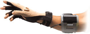 |
| Figure 1.17 The Cyberglove II. Photo courtesy of Cyberglove Systems LLC. |
The Cyberglove II is wireless via Bluetooth and is available in 18- and 22-sensor models. The 18-sensor model measures most finger rotations, abduction, thumb crossover, palm arch, and wrist rotations. The 22-sensor model adds a sensor for the distal joint of the index, middle, ring, and pinkie fingers. The sensors can capture a minimum rotation of less than one degree and can work at up to about 90 samples per second. Like many other similar devices, it requires a third-party device in order to measure global positioning and orientation. Depending on its configuration, each glove can cost many thousands of dollars.
Applications of Motion Capture
Most motion capture equipment was originally developed with applications other than entertainment in mind. Such devices have been used for many years before becoming viable tools for 3D computer graphics.
The main markets that currently benefit from motion capture are medicine, sports, entertainment, and law, but there are smaller markets that are also taking advantage of the technology. For example, motion capture equipment is used to help design ergonomic environments. Also, it is used for automobile safety tests: The motion of crash test dummies is captured and analyzed.
Medicine
In clinical circles, motion capture is called 3D biological measuring or 3D motion analysis. It is used to generate biomechanical data to be used for gait analysis and several orthopedic applications, such as joint mechanics, analysis of the spine, prosthetic design, and sports medicine. It has always been the largest segment user of the technology, but entertainment uses are growing faster.
There have been a great number of studies of gait performed with patients of all ages and conditions. The first ones were made by Etienne Jules Marey and Eadweard Muybridge in the late 1800s using photographic equipment.
Muybridge's studies started when he was hired by Leland Stanford, governor of California, to study the movement of his race horses in order to prove that all four hooves left the ground simultaneously at a given point during gallop. In 1876, Muybridge succeeded by photographing a galloping horse using 24 cameras (Figure 1.18). He then continued his studies of human and animal motion for many years. His paper on the subject, “Animal Locomotion,” was published in 1884 and is still one of the most complete studies in the area.
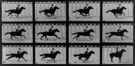 |
| Figure 1.18 Muybridge's galloping horse photographs. Photo courtesy of Eadweard Muybridge Collection, Kingston Museum. |
A professor of natural history, Etienne Marey used only one camera to study movement, as opposed to the multiple-camera configuration used by Muybridge. Even though they met in 1881, Marey and Muybridge followed separate paths in their research. Studies continued in this fashion for a century, but until the introduction of optical motion capture systems in the 1970s, the research yielded almost no benefits.
Of the current life sciences' applications, gait analysis is very useful because it accurately separates all the different mechanisms that are used during the multiple phases of a walk cycle in a way that makes it easy to detect certain abnormalities and changes. For example, gait analysis helps to measure any degree of change in conditions such as arthritis or strokes. It is also used along with other tests to determine treatment for certain pathological conditions that affect the way we walk, such as cerebral palsy. Rehabilitation by gait training is used for patients with pelvis, knee, or ankle problems.
There are many other potential applications for motion capture in the medical field. Once the current systems' limitations are surpassed, it will be possible to use motion capture to align patients and imagery in operating rooms, to compensate patient movements during MRI sessions, or even to make widely available the current applications that are possible only in special labs. The requirement will be a real-time motion capture system with great accuracy that can function in any environment.
Sports
Sports analysis is a major application of motion capture. 3D data is being used extensively to improve the performance of athletes in sports such as golf, tennis, gymnastics, and even swimming by studying the performance of professionals and dissecting and classifying the different components of the movement. As motion capture technology improves to the point at which undisturbed data collection is possible, the potential uses will become even greater in this field.
There are a few motion capture studios across the country dedicated exclusively to the analysis of sports, especially golf. For a few hundred dollars, any golfer can have his or her swing analyzed or compared with the swing of a professional golfer. Visualization software allows the studios to study the athlete's motions to find any problem areas.
The market for sports analysis is mostly amateur sports enthusiasts, but professionals look for help as well. Biovision, a company that used to operate three sports analysis studios across the country, claimed to have helped professional golfer John Daly to find a problem related to opposite movements of his hips and shoulders that happened for one-tenth of a second during his swing. Tiger Woods has done his share of motion-captured golfing for all his PGA video games. His swing has been analyzed and broken down to the smallest component in order to teach others what a perfect swing must look like.
The benefit of using motion capture rather than video for this kind of sports application is that motion capture yields a 3D representation of the motion that can be examined from any possible angle. This is true even if the video could be recorded at higher speed than the normal 30 frames per second. To analyze a fast sports action such as a golf swing or a baseball pitch, it is required to have at least a few hundred frames or samples per second.
The future of motion capture in sports is very bright. Newer systems will be able to carry out sports analysis outside of the lab. All track and field events will be analyzed at the track, its actual venue, and so will all other sports. In addition, the data captured will have many additional uses, such as real-time integration into video games via gaming networks such as X-Box live. It will be possible to watch an auto race from any desired camera in real time rendered on the gaming console and introduce a virtual car to participate in the race remotely.
Broadcasters are always looking for ways to enhance the sports watching experience. Having accurate position data of athletes in any sport is a very attractive prospect for generating eye-catching graphics and previously unavailable statistics. Once a game of football can be captured in real time, we will be able to watch rendered instant replays from any angle. The data will be used as an ongoing biomechanical profile for each player. It could even be used to diagnose injuries in real time.
Figure 1.19 shows how motion capture data could be used to enhance the broadcast of a soccer match. For the application in the image only one captured marker is required per player and that makes this application one of the closest ones to being possible. There are a few systems that analyze video and deliver motion data of such events, but technology is still not up to par for real-time applications. Instead, most current systems are mostly used to calculate estimated speed and total distance covered by each player. In a year or two, this is the way we'll be starting to look at broadcast sports.
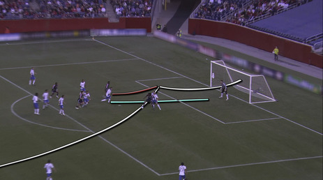 |
| Figure 1.19 Motion capture will be used to generate graphics to enhance any sporting event broadcast. |
Entertainment
The entertainment industry is the fastest growing market segment for motion capture; although not yet the largest, it certainly is the segment with the highest profile. Of the different entertainment applications, the use of motion capture in video games is currently the most widespread and the best accepted and understood. Television and feature film applications of motion capture are still migrating from an experimental market to a viable medium.
Video Games
Even though the use of motion capture in entertainment started in television and film, those markets remain resistant to widespread use of the tool. The video game industry was the first segment of entertainment to embrace motion capture as a viable tool for character motion, whereas motion capture is used on almost every video game that involves human motion. It started doing so at a time when the motion capture hardware and software was still producing low-quality results at a high, but not extreme cost. At the time, video games didn't require or rather couldn't handle high-quality motion data because they lacked the memory and rendering power to create complicated graphics, so the two industries evolved together and as rendering power increased, so did the camera resolution needed to produce the better motion quality. Video games today can handle just as high-resolution motion data as feature films.
While applications in video gaming are mostly in game production, actual performance gaming is growing fast. In October 2003, Sony released the Eye Toy, a camera to accompany the PlayStation 2. It came with a few games driven by the players' motions. The games were quite basic and weren't very compelling, but the device found a small market and over the years has been evolving, selling more than 10 million units to date. The Eye Toy is still a single camera that can capture 2D motion under certain circumstances, so games still need to be developed expressly for the device in order to work properly. Until true 3D data can be achieved, players won't be able to use their performances to power their current favorite games that are not designed for a particular input device.
Nintendo released the Wii at the end of 2006 and by the end of 2009 had sold close to 70 million units, making it the undisputed leader in console gaming. This is relevant because the Wii is designed for performance gaming and its players are willing to give up certain performance and graphic capabilities in favor of better immersion. The included input device contains an accelerometer and an infrared optical sensor that enables it to calculate an estimate of the player's movements. The device does not exactly capture the position of the player, but just the motion. The difference is that it won't tell you where it is in space at any given point in time, but it will tell you where it's going and how fast. In other words, the motion captured by the Wii Remote is relative to an arbitrary coordinate system that is controlled by the game. The Eye Toy has a fixed coordinate system but it's only 2D, while the Wii Remote has a 3D arbitrary coordinate system. Both systems' restrictions make it necessary to develop games that can operate within their capabilities.
In reaction to Wii's success, Microsoft and Sony have been busy developing their own performance gaming devices. Microsoft has demonstrated its Project Natal, which is an optical-based system. The device contains an RBG camera and a depth sensor, which is a monochrome camera working with an infrared projector to calculate 3D depth. Microsoft claims that the device will be capable of capturing movement, orientation, and gestures, but no specifications as far as accuracy, speed, or latency are available as of yet.
Sony has demonstrated its PlayStation Move device, which is a motion-sensing wand not unlike the Wii Remote, except it also uses their existing Eye Toy technology to enhance the motion complexity capabilities of the device.
Television
The use of performance animation in animated TV shows is a small market that had been growing slowly but has met with several obstacles. The main problem is that motion capture has been used primarily as a cost-cutting tool, resulting in an unexpected quality trade-off. Shows that used performance animation in the past have usually not included a budget for modifying the animation beyond the performance. An example of a show with this problem was The Real Adventures of Jonny Quest, in which only 'a few minutes per show contain any kind of computer animation.
Other cartoon shows have been successful in using performance animation in their entirety. Most of these shows have been produced by the company that is actually collecting the motion, and the motion is captured in real time in most cases, so there are no surprises in what the quality of the final animation will be. Companies that have succeeded in producing these kinds of shows are Medialab Technology, with Donkey Kong Country, and Modern Cartoons, with Jay-Jay the Jet Plane.
In television, commercials and music videos remain a small but consistent market as their budgets are larger than those of cartoon shows. Music videos have benefited from motion capture since the early 1990s, when Homer and Associates produced computer graphics based on performance animation for music videos by Peter Gabriel, Vince Neil, and TLC.
Feature Films
The main applications of motion capture in feature films used to be digital extras, digital stunts, and digital crowds, but as technology advances, main characters have been created using performance capture. Digital extras are background characters that for one reason or another have to be digitally generated. An example of such a case is a shot of the ship in the feature film Titanic as it leaves port. A live shot like this would be filmed with a helicopter and a lot of extras walking on deck, but since the actual ship did not exist, a miniature ship was shot, using a motion control camera. Because of the size of the shot, filming real people in green screen to composite over the ship would have been impossible, so the only solution was to create digital extras.
Digital stunts are actions that are either not humanly possible or need to be seen on screen performed by a person other than the stunt person. After a stunt is captured, it can only be enhanced to a certain level before the realistic motion is lost; thus, if a stunt is not humanly possible, it is best to hand it to a good character animator who specializes in realistic motion. Another kind of digital stunt involves applying motion data from a stunt person to a digital version of a known actor.
Motion capture is a good money-saving tool to use for the digital crowd scenes in which no interactions between characters occur. A perfect scenario would be a crowded stadium where some kind of sport is being played. A computer-generated crowd could be procedurally animated by first capturing different versions of each crowd reaction. As the game proceeds, the crowd may go into a cheering frenzy or be bored or angry. When one of the teams playing the sport scores, part of the crowd will be angry, others will be excited, and some will be ambivalent. A percentage of the crowd would be animated by using randomly selected angry cycles, another group would be animated by the cheering cycles, and the rest by the ambivalent cycles.
Animated films using motion capture have been also popular. The film Happy Feet was produced in Australia and went on to win an Academy Award for Best Animated Feature. Another example of an animated feature using motion capture is Monster House, produced by Robert Zemeckis.
The latest and, by far, most popular use of performance capture in any medium is for main characters and creatures. Films like The Hulk, The Lord of the Rings trilogy, King Kong, and the Pirates of the Caribbean series all used it for main characters.
Films like The Polar Express, where seven digital characters were based on Tom Hanks' performance, broke ground for what is now known as motion-captured films. The latest and most successful to date is James Cameron's Avatar. Budgets for these films are still extremely high; this is why only directors like Robert Zemeckis and James Cameron have been able to experiment in this medium. Eventually, as technology improves, budgets will become more accessible.
Law
Motion capture is applied in law to produce reconstructive videos of events. These videos are used as evidence in trials to aid the jury in understanding a witness's opinion about a particular order of events. According to a study conducted by the American Bar Association, this kind of evidence is much more effective with jurors than any other demonstrative evidence.
An example of an effective use of motion capture in the legal context is the video produced by Failure Analysis to recreate the events of the murder of Nicole Brown Simpson and Ronald Goldman during the O.J. Simpson trial. The video wasn't actually used as evidence in the trial, but it serves as an example of the kind of animation that could be used in a court of law.
To be admissible, the animation must be very plain, without any complex lighting, texture mapping, or detailed models, and, like any other evidence, it must meet the local and federal rules of evidence. In most cases, it has to be accompanied by supporting testimony from the animation creators, during either trial or deposition. Many animation companies specialize in all aspects of evidence animation, from its preparation to the presentation in court.
Security and Defense
Motion capture has been used in the military for many years, mainly in tracking helmets for pilots and other operators of combat vehicles. Tracking the line of sight of pilots has proven to be a great way to help aim weapons and to receive critical visual information.
Other uses in this field include troop training aid through simulation. Currently, it is mostly used for production, but eventually will be widely used to acquire exact troop position in the virtual or real training field. Positioning of troops and equipment in large area exercises will allow the instructors to evaluate everything that happens in the exercise by looking at a large real-time computer-generated visualization. Troops then will be debriefed using the 3D created simulation, so they can learn where to improve.
In secured installations or amusement parks, personnel and visitors can carry a tag at all times, allowing the tracking of all their movements in real time. Tagging will allow the system to provide entry privileges to certain areas and will also keep a history of personnel and visitor flow in the facility. Certain items and equipment can also be tagged in order to keep real-time account of its position at all times. There are already some GPS and RTLS versions of this application. Legoland in Denmark has had an RTLS child-tracking system for several years now. For child safety at the mall or anywhere else, parents can track their children by having them carry a mobile phone that they can track online.
Granted this is not performance capture, but it is capture of motion and it is relevant because it potentially is a much larger market than any other that exists today, even in entertainment. In fact, asset tracking is already a fast-growing market in hospitals and other facilities using RTLS.
Engineering
Motion capture is used in the engineering process for design, safety, and ergonomic testing. Through simulated human interaction with engineering models, engineers determine the functionality of their design prior to building expensive prototypes. Also, through better enabling augmented reality technology, motion capture will open the door to more efficient work flow and training methods.
Ford Motor Company has developed a system called Human Occupant Package Simulator (HOPS). The system is basically a large database of captured movements of drivers and passengers inside vehicles. Ford designers use digital humans driven by these motion datasets inside virtual vehicle designs to analyze their interactions with the vehicles. This helps them improve the ergonomics of their designs as much as possible before having to build models and prototypes.
Future Applications
There are many applications that do not currently utilize motion capture yet due to the limitations of existing systems. These markets include the social networking, location-based gaming, engineering, and sports broadcast industries.
Potentially, a location-based game such as laser tag could be carried out in a virtual world. Players would wear motion capture tags and a wireless stereoscopic head-mounted display. The virtual world's obstacles would match the real venue's, but all the decorations would be very different and the players' digital counterparts could take many different creature shapes. Weapons would also be greatly enhanced, resulting in a very realistic and immersive experience. An application like this is exactly what for many years has been the promise of what virtual reality is supposed to feel like. Players wouldn't even have to be in the same physical venue to participate. In the same manner, social networking could evolve into virtual reality applications where people meet using their chosen avatar without leaving their physical home.
Another interesting future application is in machine and vehicle service and maintenance. Imagine a head-mounted display capable of guiding a technician to a problem area inside an aircraft, showing internal parts based on actual CAD models. By tracking the display with great accuracy, the system will match the position of the real and virtual worlds, and it would make it very easy to find an exact location of a problem inside a very complex machine. It would be exactly like looking through walls or the fuselage of a plane.
Sports broadcasting will be revolutionized by newer positioning technologies. Players' performances will be captured in real time, allowing for instant replays from any angle and even real-time injury diagnosis. The data generated will be also used to create previously unavailable statistics, much loved by sports fans, and to make sure referees make fewer mistakes. Eventually, data from the game could be sent to video game consoles to allow home players to participate in some way in the event, for example, by driving a virtual car around a racetrack at the same time as a real race is happening.
It is clear that knowing where things are and how they move is a big part of the future. It only takes a little imagination to come up with new and exciting ways to use motion capture once it is unrestricted and cost effective.
..................Content has been hidden....................
You can't read the all page of ebook, please click here login for view all page.