
NR Overview
Abstract
This chapter provides an overview of NR, its design principles, and the most important technology components.
Keywords
NR; ultra-lean; forward compatibility; beam-centric
Fig. 5.1 outlines the timeline for the NR development within 3GPP. The technical work on NR was initiated in the spring of 2016 as a study item in 3GPP release 14, based on a kick-off workshop in the fall of 2015. During the study item phase, different technical solutions were studied, but given the tight time schedule, some technical decisions were taken already in this phase. The work continued into a work item phase in release 15, resulting in the first version of the NR specifications available by the end of 2017, before the closure of 3GPP release 15 in mid-2018. The reason for the intermediate release of the specifications, before the end of release-15, is to meet commercial requirements on early 5G deployments.
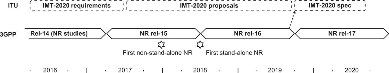
The first specification from December 2017, which is the focus of this book, is limited to non-standalone NR operation (see Chapter 6), implying that NR devices rely on LTE for initial access and mobility. The final release-15 specifications support standalone NR operation as well. The difference between standalone and non-standalone primarily affects higher layers and the interface to the core network; the basic radio technology is the same in both cases.
During the development of release 15, the focus was on eMBB and (to some extent) URLLC type of services. For massive machine-type communication (mMTC), LTE-based technologies such as eMTC and NB-IoT [28,58] can be used with excellent results. The support for LTE-based massive MTC on a carrier overlapping with an NR carrier has been accounted for in the design of NR (see Chapter 17), resulting in an integrated overall system capable of handling a very wide range of services. Native NR support for extended mMTC, as well as special technology features such as direct device-to-device connectivity, in 3GPP referred to as sidelink transmission, will be addressed in later releases.
In parallel to the work on the NR radio-access technology in 3GPP, a new 5G core network has been developed, responsible for functions not related to the radio access but needed for providing a complete network. However, it is possible to connect the NR radio-access network also to the legacy LTE core network known as the Evolved Packet Core (EPC). In fact, this is the case when operating NR in non-standalone mode where LTE and EPC handle functionality like connection set-up and paging and NR primarily provides a data-rate and capacity booster. Later releases will introduce standalone operation with NR connecting to the 5G core.
The remaining part of this chapter provides an overview of NR radio access including basic design principles and the most important technology components of NR release 15. The chapter can either be read on its own to get a high-level overview of NR, or as an introduction to the subsequent Chapters 6–19, which provide a detailed description of the NR.
Compared to LTE, NR provides many benefits. Some of the main ones are:
- • exploitation of much higher-frequency bands as a mean to obtain additional spectra to support very wide transmission bandwidths and the associated high data rates;
- • ultra-lean design to enhance network energy performance and reduce interference;
- • forward compatibility to prepare for future, yet unknown, use cases and technologies;
- • low latency to improve performance and enable new use cases; and
- • a beam-centric design enabling extensive usage of beamforming and a massive number of antenna elements not only for data transmission (which to some extent is possible in LTE) but also for control-plane procedures such as initial access.
The first three can be classified as design principles (or requirements on the design) and will be discussed first, followed by a discussion of the key technology components applied to NR.
5.1 Higher-Frequency Operation and Spectrum Flexibility
One key feature of NR is a substantial expansion in terms of the range of spectra in which the radio-access technology can be deployed. Unlike LTE, where support for licensed spectra at 3.5 GHz and unlicensed spectra at 5 GHz are just being introduced, NR supports licensed-spectrum operation from below 1 GHz up to 52.6 GHz1 already from its first release, with extension to unlicensed spectra also already being planned for.
Operation at mm-wave frequencies offers the possibility for large amounts of spectrum and associated very wide transmission bandwidths, thereby enabling very high traffic capacity and extreme data rates. However, higher frequencies are also associated with higher radio-channel attenuation, limiting the network coverage. Although this can partly be compensated for by means of advanced multi-antenna transmission/reception, which is one of the motivating factors for the beam-centric design in NR, a substantial coverage disadvantage remains, especially in non-line-of-sight and outdoor-to-indoor propagation conditions. Thus, operation in lower-frequency bands will remain a vital component for wireless communication also in the 5G era. Especially, joint operation in lower and higher spectra, for example 2 GHz and 28 GHz, can provide substantial benefits. A higher-frequency layer, with access to a large amount of spectra can provide service to a large fraction of the users despite the more limited coverage. This will reduce the load on the more bandwidth-constrained lower-frequency spectrum, allowing the use of this to focus on the worst-case users [66].
Another challenge with operation in higher-frequency bands is the regulatory aspects. For non-technical reasons, the rules defining the allowed radiation changes at 6 GHz, from a SAR-based limitation to a more EIRP-like limitation. Depending on the device type (handheld, fixed, etc.), this may result in a reduced transmission power, making the link budget more challenging than what propagation conditions alone may indicate and further stressing the benefit of combined low-frequency/high-frequency operation.
5.2 Ultra-Lean Design
An issue with current mobile-communication technologies is the amount of transmissions carried by network nodes regardless of the amount of user traffic. Such signals, sometimes referred to as “always-on” signals, include, for example, signals for base-station detection, broadcast of system information, and always-on reference signals for channel estimation. Under the typical traffic conditions for which LTE was designed, such transmissions constitute only a minor part of the overall network transmissions and thus have a relatively small impact on the network performance. However, in very dense networks deployed for high peak data rates, the average traffic load per network node can be expected to be relatively low, making the always-on transmissions a more substantial part of the overall network transmissions.
The always-on transmissions have two negative impacts:
The ultra-lean design principle aims at minimizing the always-on transmissions, thereby enabling higher network energy performance and higher achievable data rates.
In comparison, the LTE design is heavily based on cell-specific reference signals, signals that a device can assume are always present and use for channel estimation, tracking, mobility measurements, etc. In NR, many of these procedures have been revisited and modified to account for the ultra-lean design principle. For example, the cell-search procedures have been redesigned in NR compared to LTE to support the ultra-lean paradigm. Another example is the demodulation reference-signal structure where NR relies heavily on reference signals being present only when data are transmitted but not otherwise.
5.3 Forward Compatibility
An important aim in the development of the NR specification was to ensure a high degree of forward compatibility in the radio-interface design. In this context, forward compatibility implies a radio-interface design that allows for substantial future evolution, in terms of introducing new technology and enabling new services with yet unknown requirements and characteristics, while still supporting legacy devices on the same carrier.
Forward compatibility is inherently difficult to guarantee. However, based on experience from the evolution of previous generations, 3GPP agreed on some basic design principles related to NR forward compatibility as quoted from [3]:
- • Maximizing the amount of time and frequency resources that can be flexibly utilized or that can be left blank without causing backward compatibility issues in the future;
- • Minimizing transmission of always-on signals;
- • Confining signals and channels for physical layer functionalities within a configurable/allocable time/frequency resource.
According to the third bullet one should, as much as possible, avoid having transmissions on time/frequency resources fixed by the specification. In this way one retains flexibility for the future, allowing for later introduction of new types of transmissions with limited constraints from legacy signals and channels. This differs from the approach taken in LTE where, for example, a synchronous hybrid-ARQ protocol is used, implying that a retransmission in the uplink occurs at a fixed point in time after the initial transmission. The control channels are also vastly more flexible in NR compared to LTE in order not to unnecessarily block resources.
Note that these design principles partly coincide with the aim of ultra-lean design as described above. There is also a possibility in NR to configure reserved resources, that is, time-frequency resources that, when configured, are not used for transmission and thus available for future radio-interface extensions. The same mechanism can also be used for LTE-NR coexistence in the case of overlapping LTE and NR carriers.
5.4 Transmission Scheme, Bandwidth Parts, and Frame Structure
Similar to LTE [28], OFDM was found to be a suitable waveform for NR due to its robustness to time dispersion and ease of exploiting both the time and frequency domain when defining the structure for different channels and signals. However, unlike LTE where DFT-precoded OFDM is the sole transmission scheme in the uplink, NR uses conventional, that is, non-DFT-precoded OFDM, as the baseline uplink transmission scheme due to the simpler receiver structures in combination with spatial multiplexing and an overall desire to have the same transmission scheme in both uplink and downlink. Nevertheless, DFT-precoding can be used as a complement in the uplink for similar reasons as in LTE, namely to enable high power-amplifier efficiency on the device side by reducing the cubic metric [60]. Cubic metric is a measure of the amount of additional power back-off needed for a certain signal waveform.
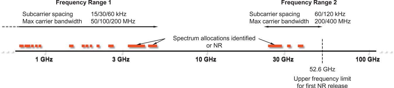
To support a wide range of deployment scenarios, from large cells with sub-1 GHz carrier frequency up to mm-wave deployments with very wide spectrum allocations, NR supports a flexible OFDM numerology with subcarrier spacings ranging from 15 kHz up to 240 kHz with a proportional change in cyclic prefix duration. A small subcarrier spacing has the benefit of providing a relatively long cyclic prefix in absolute time at a reasonable overhead while higher subcarrier spacings are needed to handle, for example, the increased phase noise at higher carrier frequencies. Up to 3300 subcarriers are used although the maximum total bandwidth is limited to 400 MHz, resulting in the maximum carrier bandwidths of 50/100/200/400 MHz for subcarrier spacings of 15/30/60/120 kHz, respectively. If even larger bandwidths are to be supported, carrier aggregation can be used.
Although the NR physical-layer specification is band-agnostic, not all supported numerologies are relevant for all frequency bands (see Fig. 5.2). For each frequency band, radio requirements are therefore defined for a subset of the supported numerologies as illustrated in Fig. 5.2. The frequency range 0.45–6 GHz is commonly referred to as frequency range 1 (FR1) in the specifications, while the range 24.25–52.6 GHz is known as FR2. Currently, there is no NR spectrum identified between 6 GHz and 24.25 GHz. However, the basic NR radio-access technology is spectrum agnostic and the NR specifications can easily be extended to cover additional spectra, for example, spectra from 6 GHz up to 24.25 GHz.
In LTE, all devices support the maximum carrier bandwidth of 20 MHz. However, given the very wide bandwidths possible in NR, it is not reasonable to require all devices to support the maximum carrier bandwidth. This has implications on several areas and requires a design different from LTE, for example the design of control channels as discussed later. Furthermore, NR allows for device-side receiver-bandwidth adaptation as a means to reduce the device energy consumption. Bandwidth adaptation refers to the use of a relatively modest bandwidth for monitoring control channels and receiving medium data rates, and dynamically opens up a wideband receiver only when needed to support very high data rates.
To handle these two aspects NR defines bandwidth parts that indicate the bandwidth over which a device is currently assumed to receive transmissions of a certain numerology. If a device is capable of simultaneous reception of multiple bandwidths parts, it is in principle possible to, on a single carrier, mix transmissions of different numerologies for a single device, although release 15 only supports a single active bandwidth part at a time.
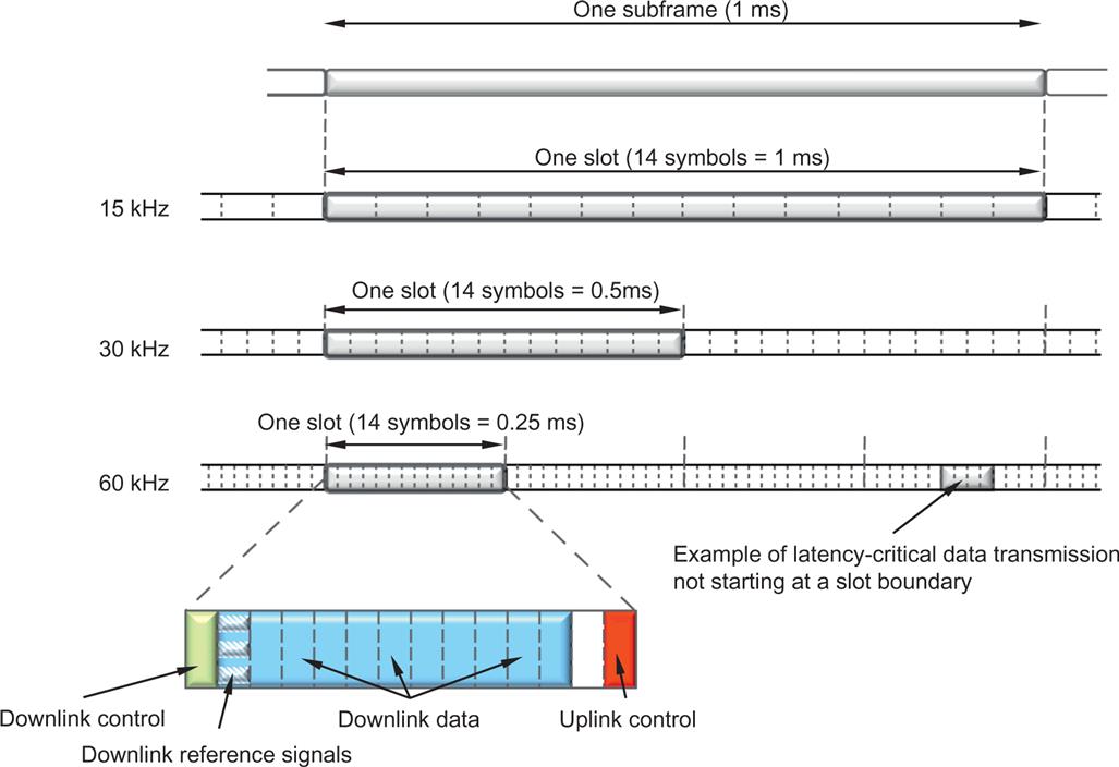
The NR time-domain structure is illustrated in Fig. 5.3 with a 10-ms radio frame divided into ten 1-ms subframes. A subframe is in turn divided into slots consisting of 14 OFDM symbols each, that is, the duration of a slot in milliseconds depends on the numerology. For the 15-kHz subcarrier spacing, an NR slot has a structure that is identical to the structure of an LTE subframe, which is beneficial from a coexistence perspective. Since a slot is defined as a fixed number of OFDM symbols, a higher subcarrier spacing leads to a shorter slot duration. In principle this could be used to support lower-latency transmission, but as the cyclic prefix also shrinks when increasing the subcarrier spacing, it is not a feasible approach in all deployments. Therefore, NR supports a more efficient approach to low latency by allowing for transmission over a fraction of a slot, sometimes referred to as “mini-slot” transmission. Such transmissions can also preempt an already ongoing slot-based transmission to another device, allowing for immediate transmission of data requiring very low latency.
Having the flexibility of starting a data transmission not only at the slot boundaries is also useful when operating in unlicensed spectra. In unlicensed spectra the transmitter is typically required to ensure that the radio channel is not occupied by other transmissions prior to starting a transmission, a procedure commonly known as “listen-before-talk.” Clearly, once the channel is found to be available it is beneficial to start the transmission immediately, rather than wait until the start of the slot, in order to avoid some other transmitter initiating a transmission on the channel.
Operation in the mm-wave domain is another example of the usefulness of “mini-slot” transmissions as the available bandwidth in such deployments is often very large and even a few OFDM symbols can be sufficient to carry the available payload. This is of particular use in conjunction with analog beamforming, discussed below, where transmissions to multiple devices in different beams cannot be multiplexed in the frequency domain but only in the time domain.
Unlike LTE, NR does not include cell-specific reference signals but solely relies on user-specific demodulation reference signals for channel estimation. Not only does this enable efficient beamforming and multi-antenna operation as discussed below, it is also in line with the ultra-lean design principle described above. In contrast to cell-specific reference signals, demodulation reference signals are not transmitted unless there are data to transmit, thereby improving network energy performance and reducing interference.
The overall NR time/frequency structure, including bandwidth parts, is the topic of Chapter 7.
5.5 Duplex Schemes
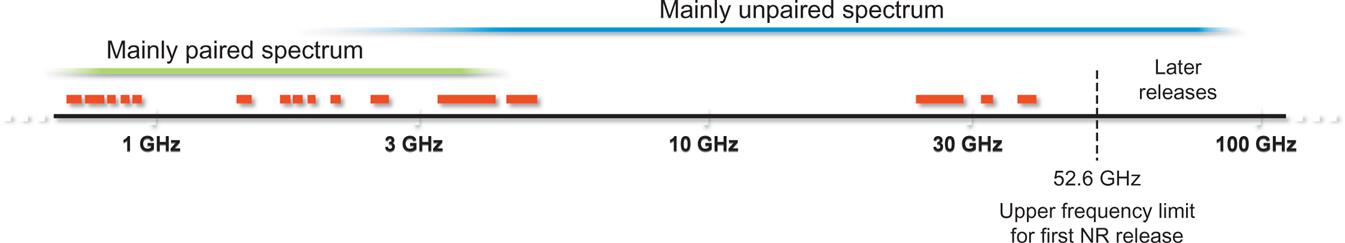
The duplex scheme to use is typically given by the spectrum allocation at hand. For lower-frequency bands, allocations are often paired, implying frequency-division duplex (FDD) as illustrated in Fig. 5.4. At higher-frequency bands, unpaired spectrum allocations are increasingly common, calling for time-division duplex (TDD). Given the significantly higher carrier frequencies supported by NR compared to LTE, efficient support for unpaired spectra is an even more critical component of NR, compared to LTE.
NR can operate in both paired and unpaired spectra using one common frame structure, unlike LTE were two different frame structures were used (and later expanded to three when support for unlicensed spectra was introduced in release 13). The basic NR frame structure is designed such that it can support both half-duplex and full-duplex operation. In half duplex, the device cannot transmit and receive at the same time. Examples hereof are TDD and half-duplex FDD. In full-duplex operation, on the other hand, simultaneous transmission and reception is possible with FDD as a typical example.
As already mentioned, TDD increases in importance when moving to higher-frequency bands where unpaired spectrum allocations are more common. These frequency bands are less useful for wide-area coverage with very large cells due to their propagation conditions but are highly relevant for local-area coverage with smaller cell sizes. Furthermore, some of the problematic interference scenarios in wide-area TDD networks are less pronounced in local area deployments with lower transmission power and below-rooftop antenna installations. In such denser deployments with smaller cell sizes, the per-cell traffic variations are more rapid compared to large-cell deployments with a large number of active devices per cell. To address such scenarios, dynamic TDD, that is, the possibility for dynamic assignment and reassignment of time-domain resources between the downlink and uplink transmission directions, is a key NR technology component. This is in contrast to LTE where the uplink–downlink allocation does not change over time.2 Dynamic TDD enables following rapid traffic variations which are particularly pronounced in dense deployments with a relatively small number of users per cell. For example, if a user is (almost) alone in a cell and needs to download a large object, most of the resources should be utilized in the downlink direction and only a small fraction in the uplink direction. At a later point in time, the situation may be different and most of the capacity is needed in the uplink direction.
The basic approach to dynamic TDD is for the device to monitor for downlink control signaling and follow the scheduling decisions. If the device is instructed to transmit, it transmits in the uplink, otherwise it will attempt to receive any downlink transmissions. The uplink–downlink allocation is then completely under the control of the scheduler and any traffic variations can be dynamically tracked. There are deployment scenarios where dynamic TDD may not be useful, but it is much simpler to restrict the dynamics of a dynamic scheme in those scenarios when needed rather than trying to add dynamics to a fundamentally semistatic design as LTE. For example, in a wide-area macro network with above-rooftop antennas, the intercell interference situation requires coordination of the uplink–downlink allocation between the cells. In such situations, a semi-static allocation is appropriate with operation along the lines of LTE. This can be obtained by the appropriate scheduling implementation. There is also the possibility to semistatically configure the transmission direction of some or all of the slots, a feature that can allow for reduced device energy consumption as it is not necessary to monitor for downlink control channels in slots that are a priori known to be reserved for uplink usage.
5.6 Low-Latency Support
The possibility for very low latency is an important characteristic of NR and has impacted many of the NR design details. One example is the use of “front-loaded” reference signals and control signaling, as illustrated in Fig. 5.3. By locating the reference signals and downlink control signaling carrying scheduling information at the beginning of the transmission and not using time-domain interleaving across OFDM symbols, a device can start processing the received data immediately without prior buffering, thereby minimizing the decoding delay. The possibility for transmission over a fraction of a slot, sometimes referred to as “mini-slot” transmission, is another example.
The requirements on the device (and network) processing times are tightened significantly in NR compared to LTE. As an example, a device has to respond with a hybrid-ARQ acknowledgment of approximately one slot (or even less depending on device capabilities) after receiving a downlink data transmission. Similarly, the time from grant reception to uplink data transfer is in the same range.
The higher-layer protocols MAC and RLC have also been designed with low latency in mind with header structures chosen to enable processing without knowing the amount of data to transmit (see Chapter 6). This is especially important in the uplink direction as the device may only have a few OFDM symbols after receiving the uplink grant until the transmission should take place. In contrast, the LTE protocol design requires the MAC and RLC protocol layers to know the amount of data to transmit before any processing can take place, which makes support for a very low latency more challenging.
5.7 Scheduling and Data Transmission
One key characteristic of mobile radio communication is the large and typically rapid variations in the instantaneous channel conditions stemming from frequency-selective fading, distance-dependent path loss, and random interference variations due to transmissions in other cells and by other devices. Instead of trying to combat these variations, they can be exploited through channel-dependent scheduling where the time-frequency resources are dynamically shared between users (see Chapter 14 for details). Dynamic scheduling is used in LTE as well and on a high level, the NR scheduling framework is similar to the one in LTE. The scheduler, residing in the base station, takes scheduling decisions based on channel-quality reports obtained from the devices. It also takes different traffic priorities and quality-of-service requirements into account when forming the scheduling decisions sent to the scheduled devices.
Each device monitors several physical downlink control channels (PDCCHs), typically once per slot, although it is possible to configure more frequent monitoring to support traffic requiring very low latency. Upon detection of a valid PDCCH, the device follows the scheduling decision and receives (or transmits) one unit of data known as a transport block in NR.
In the case of downlink data transmission, the device attempts to decode the downlink transmission. Given the very high data rates supported by NR, channel-coding data transmission is based on low-density parity-check (LDPC) codes [68]. LDPC codes are attractive from an implementation perspective, especially at higher code rates where they can offer a lower complexity than Turbo codes as used in LTE.
Hybrid automatic repeat-request (ARQ) retransmission using incremental redundancy is used where the device reports the outcome of the decoding operation to the base station (see Chapter 13 for details). In the case of erroneously received data, the network can retransmit the data and the device combines the soft information from multiple transmission attempts. However, retransmitting the whole transport block could in this case become inefficient. NR therefore supports retransmissions on a finer granularity known as code-block group (CBG). This can also be useful when handling preemption. An urgent transmission to a second device may use only one or a few OFDM symbols and therefore cause high interference to the first device in some OFDM symbols only. In this case it may be sufficient to retransmit the interfered CBGs only and not the whole data block. Handling of preempted transmission can be further assisted by the possibility to indicate to the first device the impacted time-frequency resources such that it can take this information into account in the reception process.
Although dynamic scheduling is the basic operation of NR, operation without a dynamic grant can be configured. In this case, the device is configured in advance with resources that can be used for uplink data transmission (or downlink data reception). Once a device has data available it can immediately commence uplink transmission without going through the scheduling request–grant cycle, thereby enabling lower latency.
5.8 Control Channels
Operation of NR requires a set of physical-layer control channels to carry the scheduling decisions in the downlink and to provide feedback information in the uplink. A detailed description of the structure of these control channels is provided in Chapter 10.
Downlink control channels are known as PDCCHs (physical downlink control channels). One major difference compared to LTE is the more flexible time-frequency structure of downlink control channels where PDCCHs are transmitted in one or more control resource sets (CORESETs) which, unlike LTE where the full carrier bandwidth is used, can be configured to occupy only part of the carrier bandwidth. This is needed in order to handle devices with different bandwidth capabilities and also in line with the principles for forward compatibility as discussed above. Another major difference compared to LTE is the support for beamforming of the control channels, which has required a different reference signal design with each control channel having its own dedicated reference signal.
Uplink control information, such as hybrid-ARQ acknowledgments, channel-state feedback for multi-antenna operation, and scheduling request for uplink data awaiting transmission, are transmitted using the physical uplink control channel (PUCCH). There are several different PUCCH formats, depending on the amount of information and the duration of the PUCCH transmission. The short PUCCH is transmitted in the last one or two symbols of a slot and can support very fast feedback of hybrid-ARQ acknowledgments in order to realize so-called self-contained slots where the delay from the end of the data transmission to the reception of the acknowledgment from the device is in the order of an OFDM symbol, corresponding to a few tens of microseconds depending on the numerology used. This can be compared to almost 3 ms in LTE and is yet another example on how the focus on low latency has impacted the NR design. For situations when the duration of the short PUCCH is too short to provide sufficient coverage, there are also possibilities for longer PUCCH durations.
For the physical-layer control channels, for which the information blocks are small compared to data transmission and hybrid-ARQ is not used, polar codes [17] have been selected. For the smallest control payloads, Reed–Muller codes are used.
5.9 Beam-Centric Design and Multi-Antenna Transmission
Support for a for a large number of steerable antenna elements for both transmission and reception is a key feature of NR. At higher-frequency bands, the large number of antenna elements are primarily used for beamforming to extend coverage, while at lower-frequency bands they enable full-dimensional MIMO, sometimes referred to as massive MIMO, and interference avoidance by spatial separation.
NR channels and signals, including those used for control and synchronization, have all been designed to support beamforming (Fig. 5.5). Channel-state information (CSI) for operation of massive multi-antenna schemes can be obtained by feedback of CSI reports based on transmission of CSI reference signals in the downlink, as well as using uplink measurements exploiting channel reciprocity.
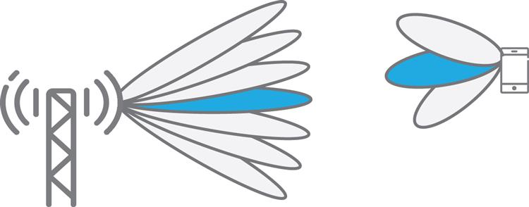
To provide implementation flexibility, NR is deliberately supporting functionality to support analog beam-forming a well as digital precoding/beam-forming (see Chapter 11). At high frequencies, analog beamforming, where the beam is shaped after digital-to-analog conversion, may be necessary from an implementation perspective, at least initially. Analog beamforming results in the constraint that a receive or transmit beam can only be formed in one direction at a given time instant and requires beam-sweeping where the same signal is repeated in multiple OFDM symbols but in different transmit beams. By having beam-sweeping possibility, it is ensured that any signal can be transmitted with a high gain, narrow beam to reach the entire intended coverage area.
Signaling to support beam-management procedures is specified, such as an indication to the device to assist selection of a receive beam (in the case of analog receive beamforming) to be used for data and control reception. For a large number of antennas, beams are narrow and beam tracking can fail, therefore beam-recovery procedures have also been defined where a device can trigger a beam-recovery procedure. Moreover, a cell may have multiple transmission points, each with beams and the beam-management procedures allow for device transparent mobility for seamless handover between the beams of different points. Additionally, uplink-centric and reciprocity-based beam management is possible by utilizing uplink signals.
With the use of a massive number of antenna elements for lower-frequency bands, the possibility to separate users spatially increases both in uplink and downlink, but requires that the transmitter has channel knowledge. For NR, extended support for such multi-user spatial multiplexing is introduced, either by using a high-resolution channel-state-information feedback using a linear combination of DFT vectors, or uplink sounding reference signals targeting the utilization of channel reciprocity.
Twelve orthogonal demodulation reference signals are specified for multi-user MIMO transmission purposes, while an NR device can maximally receive eight MIMO layers in the downlink and up to four layers in the uplink. Moreover, additional configuration of a phase tracking reference signal is introduced in NR since the increased phase noise power at high carrier frequency bands otherwise will degrade demodulation performance for larger modulation constellations, for example 64 QAM.
In addition, NR is prepared to support distributed MIMO, although the support is not complete in release 15. Distributed MIMO implies that the device can receive multiple independent physical data shared channels (PDSCHs) per slot to enable simultaneous data transmission from multiple transmission points to the same user. In essence, some MIMO layers are transmitted from one site while other layers are transmitted from another site.
Multi-antenna transmission in general, as well as a more detailed discussion on NR multi-antenna precoding, is described in Chapter 11 with beam management being the subject of Chapter 12.
5.10 Initial Access
Initial access is the procedures allowing a device to find a cell to camp on, receive the necessary system information, and to request a connection through random access. The basic structure of NR initial access, described in Chapter 16, is similar to the corresponding functionality of LTE [28]:
- • There is a pair of downlink signals, the primary synchronization signal (PSS) and the secondary synchronization signal (SSS), that is used by devices to find, synchronize to, and identify a network;
- • There is a downlink physical broadcast channel (PBCH) transmitted together with the PSS/SSS. The PBCH carries a minimum amount of system information including an indication where the remaining broadcast system information is transmitted. In the context of NR, the PSS, SSS, and PBCH are jointly referred to as a synchronization signal (SS) block;
- • There is a four-stage random-access procedure, commencing with the uplink transmission of a random-access preamble.
However, there are some important differences between LTE and NR in terms of initial access. These differences come mainly from the ultra-lean principle and the beam-centric design, both of which impact the initial access procedures and partly lead to different solutions compared to LTE.
In LTE, the PSS, SSS, and PBCH are located at the center of the carrier and are transmitted once every 5 ms. Thus, by dwelling on each possible carrier frequency during at least 5 ms, a device is guaranteed to receive at least one PSS/SSS/PBCH transmission if a carrier exists at the specific frequency. Without any a priori knowledge a device must search all possible carrier frequencies over a carrier raster of 100 kHz.
To enable higher NR network energy performance in line with the ultra-lean principle, the SS block is, by default, transmitted once every 20 ms. Due to the longer period between consecutive SS blocks, compared to the corresponding signals/channels in LTE, a device searching for NR carriers must dwell on each possible frequency for a longer time. To reduce the overall search time while keeping the device complexity comparable to LTE, NR supports a sparse frequency raster for SS block. This implies that the possible frequency-domain positions of the SS block could be significantly sparser, compared to the possible positions of an NR carrier (the carrier raster). As a consequence, the SS block will typically not be located at the center of the NR carrier, which has impacted the NR design.
The sparse SS-block raster enables a significantly reduced time for initial cell search, at the same time as the network energy performance can be significantly improved due to the longer SS-block period.
Network-side beam-sweeping is supported for both downlink SS-slock transmission and uplink random-access reception as a means to improve coverage, especially in the case of operation at higher frequencies. It is important to realize that beam sweeping is a possibility enabled by the NR design. It does not imply that it must be used. Especially at lower carrier frequencies, beam sweeping may not be needed.
5.11 Interworking and LTE Coexistence
As it is difficult to provide full coverage at higher frequencies, interworking with systems operating at lower frequencies is important. In particular, a coverage imbalance between uplink and downlink is a common scenario, especially if they are in different frequency bands. The higher transmit power for the base station compared to the mobile device results in the downlink achievable data rates often being bandwidth limited, making it more relevant to operate the downlink in a higher spectrum where wider bandwidth may be available. In contrast, the uplink is more often power-limited, reducing the need for wider bandwidth. Instead, higher data rates may be achieved on lower-frequency spectra, despite there being less available bandwidth, due to less radio-channel attenuation.
Through interworking, a high-frequency NR system can complement a low-frequency system (see Chapter 17 for details). The lower-frequency system can be either NR or LTE, and NR supports interworking with either of these. The interworking can be realized at different levels, including intra-NR carrier aggregation, dual connectivity3 with a common packet data convergence protocol (PDCP) layer, and handover.
However, the lower-frequency bands are often already occupied by current technologies, primarily LTE. Furthermore, an additional low-frequency spectrum is planned to be deployed with LTE in the relatively near future. LTE/NR spectrum coexistence, that is, the possibility for an operator to deploy NR in the same spectrum as an already existing LTE deployment has therefore been identified as a way to enable early NR deployment in lower-frequency spectra without reducing the amount of spectrum available to LTE.
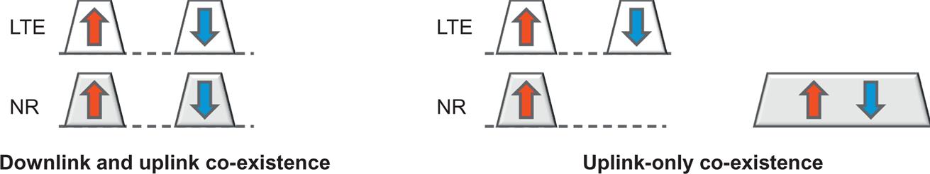
Two coexistence scenarios were identified in 3GPP and guided the NR design:
- • In the first scenario, illustrated in the left part of Fig. 5.6, there is LTE/NR coexistence in both downlink and uplink. Note that this is relevant for both paired and unpaired spectra although a paired spectrum is used in the illustration.
- • In the second scenario, illustrated in the right part of Fig. 5.6, there is coexistence only in the uplink transmission direction, typically within the uplink part of a lower-frequency paired spectrum, with NR downlink transmission taking place in the spectrum dedicated to NR, typically at higher frequencies. This scenario attempts to address the uplink–downlink imbalance discussed above. NR supports a supplementary uplink (SUL) to specifically handle this scenario.
The possibility for an LTE-compatible NR numerology based on 15-kHz subcarrier spacing, enabling identical time/frequency resource grids for NR and LTE, is one of the fundamental tools for such coexistence. The flexible NR scheduling with a scheduling granularity as small as one symbol can then be used to avoid scheduled NR transmissions to collide with key LTE signals, such as cell-specific reference signals, CSI-RS, and the signals/channels used for LTE initial access. Reserved resources, introduced for forward compatibility (see Section 5.3), can also be used to further enhance NR–LTE coexistence. It is possible to configure reserved resources matching the cell-specific reference signals in LTE, thereby enabling an enhanced NR–LTE overlay in the downlink.