
Physical-Layer Control Signaling
Abstract
To support the transmission of downlink and uplink transport channels, there is a need for certain associated control signaling. This control signaling is often referred to as L1/L2 control signaling, indicating that the corresponding information partly originates from the physical layer (Layer 1) and partly from MAC (Layer 2). In this chapter, the downlink controls signaling, including scheduling grants and assignments, will be described, followed by the uplink control signaling carrying the necessary feedback from the device.
Keywords
DCI; UCI; PDCCH; PUCCH; CORESET; search space; blind decoding; CCE
To support the transmission of downlink and uplink transport channels, there is a need for certain associated control signaling. This control signaling is often referred to as L1/L2 control signaling, indicating that the corresponding information partly originates from the physical layer (layer 1) and partly from MAC (layer 2).
In this chapter, the downlink control signaling, including scheduling grants and assignments, will be described, followed by the uplink control signaling carrying the necessary feedback from the device.
10.1 Downlink
Downlink L1/L2 control signaling consists of downlink scheduling assignments, including information required for the device to be able to properly receive, demodulate, and decode the DL-SCH on a component carrier, and uplink scheduling grants informing the device about the resources and transport format to use for uplink (UL-SCH) transmission. In addition, the downlink control signaling can also be used for special purposes such as conveying information about the symbols used for uplink and downlink in a set of slots, preemption indication, and power control.
In NR, there is only a single control channel, the physical downlink control channel (PDCCH). On a high level, the principles of the PDCCH processing in NR are similar to LTE, namely that the device tries to blindly decode candidate PDCCHs transmitted from the network using one or more search spaces. However, there are some differences compared to LTE based on the different design targets for NR as well as experience from LTE deployments:
- • The PDCCH in NR does not necessarily span the full carrier bandwidth, unlike the LTE PDCCH. This is a natural consequence of the fact that not all NR devices may be able to receive the full carrier bandwidth as discussed in Chapter 5, and led to the design of a more generic control channel structure in NR.
- • The PDCCH in NR is designed to support device-specific beamforming, in line with the general beam-centric design of NR and a necessity when operating at very high carrier frequencies with a corresponding challenging link budget.
These two aspects were to some extent addressed in the LTE EPDCCH design in release 11, although in practice EPDCCH has not been used extensively except as a basis for the control signaling for eMTC.
Two other control channels present in LTE, the PHICH and the PCFICH, are not needed in NR. The former is used in LTE to handle uplink retransmissions and is tightly coupled to the use of a synchronous hybrid-ARQ protocol, but since the NR hybrid-ARQ protocol is asynchronous in both uplink and downlink the PHICH is not needed in NR. The latter channel, the PCFICH, is not necessary in NR as the size of the control resource sets (CORESETs) does not vary dynamically and reuse of control resources for data is handled in a different way than in LTE, as discussed further below.
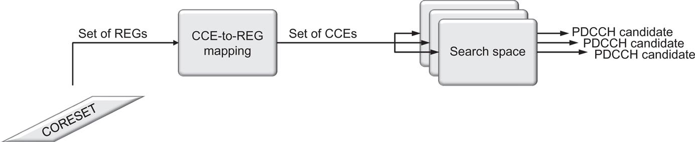
In the following sections, the NR downlink control channel, the PDCCH, will be described, including the notion of a CORESETs, the time–frequency resources upon which the PDCCH is transmitted. First, the PDCCH processing including coding and modulation will be discussed, followed by a discussion on the CORESETs structure. There can be multiple CORESETs on a carrier and part of the control resource set is the mapping from resource elements to control channel elements (CCEs). One or more CCEs from one control resource set are aggregated to form the resources used by one PDCCH. Blind detection, the process where the device attempts to detect if there are any PDCCHs transmitted to the device, is based on search spaces. There can be multiple search spaces using the resources in a single CORESET, as illustrated in Fig. 10.1. Finally, the contents of the downlink control information (DCI) will be described.
10.1.1 Physical Downlink Control Channel
The PDCCH processing steps are illustrated in Fig. 10.2. At a high level, the PDCCH processing in NR is more similar to the LTE EPDCCH than the LTE PDCCH in the sense that each PDCCH is processed independently.
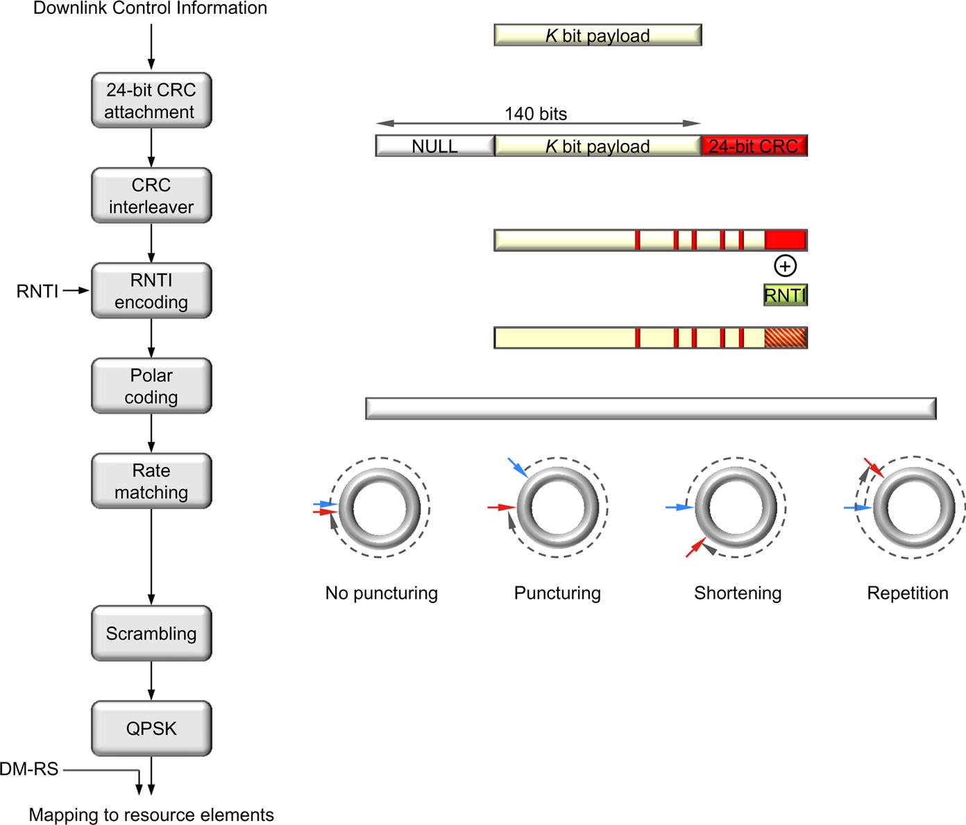
The payload transmitted on a PDCCH is known as Downlink Control Information (DCI) to which a 24-bit CRC is attached to detect transmission errors and to aid the decoder in the receiver. Compared to LTE, the CRC size has been increased to reduce the risk of incorrectly received control information and to assist early termination of the decoding operation in the receiver.
Similarly to LTE, the device identity modifies the CRC transmitted through a scrambling operation. Upon receipt of the DCI, the device will compute a scrambled CRC on the payload part using the same procedure and compare it against the received CRC. If the CRC checks, the message is declared to be correctly received and intended for the device. Thus, the identity of the device that is supposed to receive the DCI message is implicitly encoded in the CRC and not explicitly transmitted. This reduces the number of bits necessary to transmit on the PDCCH as, from a device point of view, there is no difference between a corrupt message whose CRC will not check, and a message intended for another device. Note that the RNTI does not necessarily have to be the identity of the device, the C-RNTI, but can also be different types of group or common RNTIs, for example, to indicate paging or a random-access response.
Channel coding of the PDCCH is based on Polar codes, a relatively new form of channel coding. The basic idea behind Polar codes is to transform several instances of the radio channel into a set of channels that are either noiseless or completely noisy and then transmit the information bits on the noiseless channels. Decoding can be done in several ways, but a typical approach is to use successive cancellation and list decoding. List decoding uses the CRC as part of the decoding process, which means that the error-detecting capabilities are reduced. For example, list decoding of size eight results in a loss of three bits from an error-detecting perspective, resulting in the 24-bits CRC providing error-detecting capabilities corresponding to a 21-bit CRC. This is part of the reason for the larger CRC size compared to LTE.
Unlike the tailbiting convolutional codes used in LTE, which can handle any number of information bits, Polar codes need to be designed with a maximum number of bits in mind. In NR, the Polar code has been designed to support 512 coded bits (prior to rate matching) in the downlink. Up to 140 information bits can be handled, which provides a sufficient margin for future extensions as the DCI payload size in release 15 is significantly less. To assist early termination in the decoding process, the CRC is not attached at the end of the information bits, but inserted in a distributed manner, after which the Polar code is applied. Early termination can also be achieved by exploiting the path metric in the decoder.
Rate matching is used to match the number of coded bits to the resources available for PDCCH transmission. This is a somewhat intricate process and is based on one of shortening, puncturing, or repetition of the coded bits after subblock interleaving of 32 blocks. The set of rules selecting between shortening, puncturing, and repetition, as well as when to use which of the schemes, is designed to maximize performance.
Finally, the coded and rate-matched bits are scrambled, modulated using QPSK, and mapped to the resource elements used for the PDCCH, the details of which will be discussed below. Each PDCCH has its own reference signal, which means that the PDCCH can make full use of the antenna setup, for example, be beamformed in a particular direction. The complete PDCCH processing chain is illustrated in Fig. 10.2.
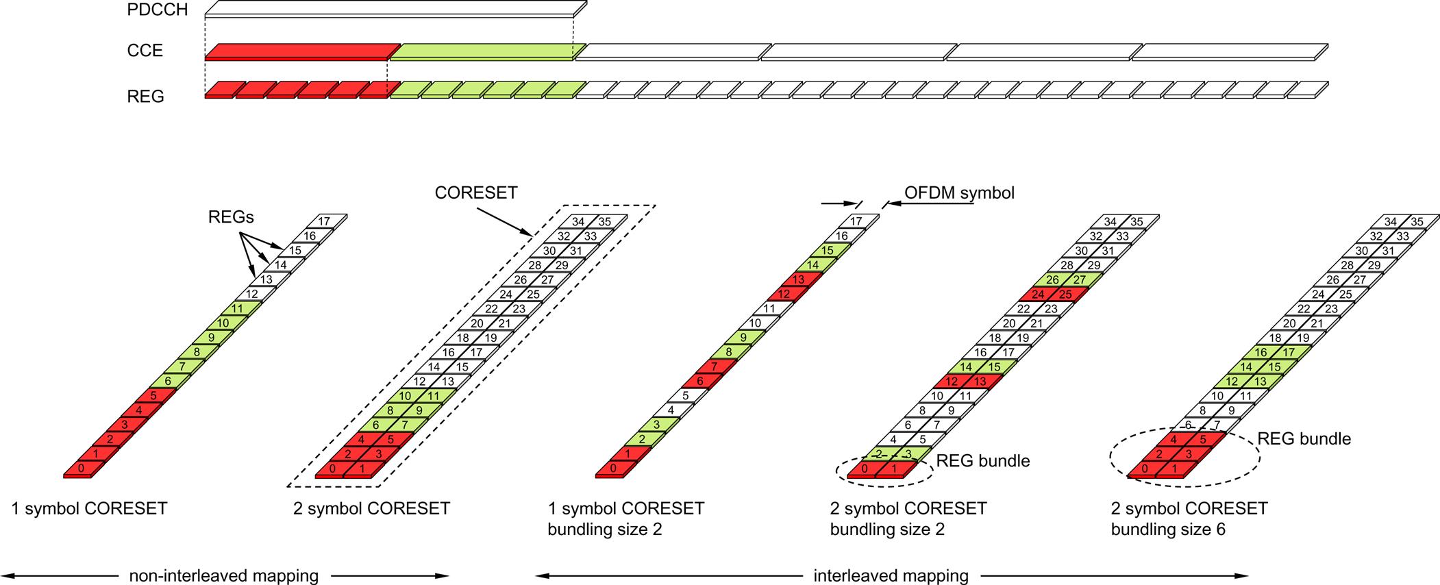
The mapping of the coded and modulated DCI to resource elements is subject to a certain structure, based on control-channel elements (CCEs) and resource-element groups (REGs). Although the names are borrowed from LTE, the size of the two differ from their LTE counterparts, as does the CCE-to-REG mapping.
A PDCCH is transmitted using 1, 2, 4, 8, or 16 contiguous control-channel elements with the number known as the aggregation level. The control-channel element is the unit upon which the search spaces for blind decoding are defined as will be discussed in Section 10.1.3. A control-channel element consists of six resource-element groups, each of which is equal to one resource block in one OFDM symbol. After accounting for the DM-RS overhead, there are 54 resource elements (108 bits) available for PDCCH transmission in one control-channel element.
The CCE-to-REG mapping can be either interleaved or non-interleaved. The motivation for having two different mapping schemes is, similarly to the case of the LTE EPDCCH, to be able to provide frequency diversity by using an interleaved mapping or to facilitate interference coordination and frequency-selective transmission of control channels by using non-interleaved mapping. The details of the CCE-to-REG mapping will be discussed in the next section as part of the overall CORESET structure.
10.1.2 Control Resource Set
Central to downlink control signaling in NR is the concept of CORESETs. A control resource set is a time–frequency resource in which the device tries to decode candidate control channels using one or more search spaces. The size and location of a CORESET in the time–frequency domain is semistatically configured by the network and can thus be set to be smaller than the carrier bandwidth. This is especially important in NR as a carrier can be very wide, up to 400 MHz, and it is not reasonable to assume all devices can receive such a wide bandwidth.
In LTE, the concept of a CORESET is not explicitly present. Instead, downlink control signaling in LTE uses the full carrier bandwidth in the first 1–3 OFDM symbols (four for the most narrowband case). This is known as the control region in LTE and in principle this control region would correspond to the “LTE CORESET” if that term would have been used. Having the control channels spanning the full carrier bandwidth was well motivated by the desire for frequency diversity and the fact that all LTE devices support the full 20 MHz carrier bandwidth (at least at the time of specifying release 8). However, in later LTE releases this lead to complications when introducing support for devices not supporting the full carrier bandwidth, for example, the eMTC devices introduced in release 12. Another drawback of the LTE approach is the inability to handle frequency-domain interference coordination between cells for the downlink control channels. To some extent, these drawbacks with the LTE control channel design were addressed with the introduction of the EPDCCH in release 11, but the EPDCCH feature has so far not been widely deployed in practice as an LTE network still needs to provide PDCCH support for initial access and to handle non-EPDCCH-capable LTE devices. Therefore, a more flexible structure is used in NR from the start.
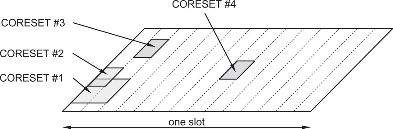
A CORESET can occur at any position within a slot and anywhere in the frequency range of the carrier (see Fig. 10.3). However, a device is not expected to handle CORESETs outside its active bandwidth part. The reason for configuring CORESETs on the cell level and not per bandwidth part is to facilitate reuse of CORSETs between bandwidth parts, for example, when operating with bandwidth adaptation as discussed in Section 14.1.1.
The first CORSET, CORESET 0, is provided by the master information block (MIB) as part of the configuration of the initial bandwidth part to be able to receive the remaining system information and additional configuration information from the network. After connection setup, a device can be configured with multiple, potentially overlapping, CORESETs in addition to using RRC signaling.
In the time domain, a CORESET can be up to three OFDM symbols in duration and located anywhere within a slot, although a common scenario, suitable for traffic scenarios when a scheduling decision is taken once per slot, is to locate the CORESET at the beginning of the slot. This is similar to the LTE situation with control channels at the beginning of each LTE subframe. However, configuring a CORESET at other time instances can be useful, for example to achieve very low latency for transmissions occupying only a few OFDM symbols without waiting for the start of the next slot. It is important to understand that a CORESET is defined from a device perspective and only indicates where a device may receive PDCCH transmissions. It does not say anything on whether the gNB actually transmits a PDCCH or not.
Depending on where the front-loaded DM-RS for PDSCH are located, in the third or fourth OFDM symbol of a slot (see Section 9.11.1), the maximum duration for a CORESET is two or three OFDM symbols. This is motivated by the typical case of locating the CORESET before the start of downlink reference signals and the associated data. In the frequency domain, a CORESET is defined in multiples of six resource blocks up to the carrier bandwidth.
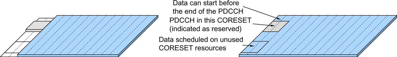
Unlike LTE, where the control region can vary dynamically in length as indicated by a special control channel (the PCFICH), a CORESET in NR is of fixed size. This is beneficial from an implementation perspective, both for the device and the network. From a device perspective, a pipelined implementation is simpler if the device can directly start to process the PDCCH without having to first decode another channel like the PCFICH in LTE. Having a streamlined and implementation-friendly structure of the PDCCH is important in order to realize the very low latency possible in NR. However, from a spectral efficiency point of view, it is beneficial if resources can be shared flexibly between control and data in a dynamic manner. Therefore, NR provides the possibility to start the PDSCH data before the end of a CORESET. It is also possible to, for a given device, reuse unused CORESET resources as illustrated in Fig. 10.4. To handle this, the general mechanism of reserved resources is used (see Section 9.10). Reserved resources that overlap with the CORESET are configured and information in the DCI indicates to the device whether the reserved resources are usable by the PDSCH or not. If they are indicated as reserved, the PDSCH is rate-matched around the reserved resources overlapping with the CORESET, and if the resources are indicated as available, the PDSCH uses the reserved resources for data except for the resources used by the PDCCH upon which the device received the DCI scheduling the PDSCH.
For each CORESET there is an associated CCE-to-REG mapping, a mapping that is described using the term REG bundle. A REG bundle is a set of REGs across which the device can assume the precoding is constant. This property can be exploited to improve the channel-estimation performance in a similar way as resource-block bundling for the PDSCH.
As already mentioned, the CCE-to-REG mapping can be either interleaved or non-interleaved, depending on whether frequency-diverse or frequency-selective transmission is desired. There is only one CCE-to-REG mapping for a given CORESET, but since the mapping is a property of the CORESET, multiple CORESETs can be configured with different mappings, which can be useful. For example, one or more CORESETs configured with non-interleaved mapping to benefit from frequency-dependent scheduling, and one or more configured with interleaved mapping to act as a fallback in case the channel-state feedback becomes unreliable due to the device moving rapidly.
The non-interleaved mapping is straightforward. The REG bundle size is six for this case, that is, the device may assume the precoding is constant across a whole CCE. Consecutive bundles of six REGs are used to form a CCE.
The interleaved case is a bit more intricate. In this case, the REG bundle size is configurable between two alternatives. One alternative is six, applicable to all CORESET durations, and the other alternative is, depending on the CORSET duration, two or three. For a duration of one or two OFDM symbols, the bundle size can be two or six, and for a duration of three OFDM symbols, the bundle size can be three or six. In the interleaved case, the REG bundles constituting a CCE are obtained using a block interleaver to spread out the different REG bundles in frequency, thereby obtaining frequency diversity. The number of rows in the block interleaver is configurable to handle different deployment scenarios (Fig. 10.5).
As part of the PDCCH reception process, the device needs to form a channel estimate using the reference signals associated with the PDCCH candidate being decoded. A single antenna port is used for the PDCCH, that is, any transmit diversity or multi-user MIMO scheme is handled in a device-transparent manner.
The PDCCH has its own demodulation reference signals, based on the same type of pseudo-random sequence as the PDSCH—the pseudo-random sequence is generated across all the common resource blocks in the frequency domain but transmitted only in the resource blocks used for the PDCCH (with one exception as discussed below). However, during initial access, the location for the common resource blocks is not yet known as it is signaled as part of the system information. Hence, for CORESET 0 configured by the PBCH, the sequence is generated starting from the first resource block in the CORESET instead.
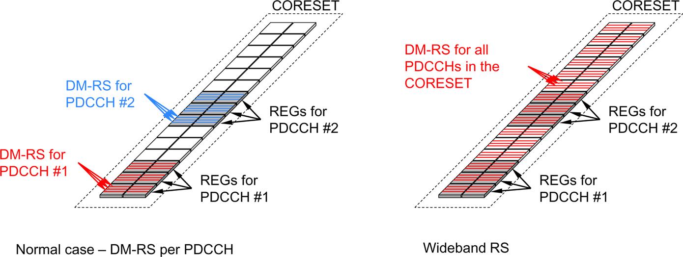
Demodulation reference-signals specific for a given PDCCH candidate are mapped onto every fourth subcarrier in a resource-element group, that is, the reference signal overhead is 1/4. This is a denser reference signal pattern than in LTE, which uses a reference signal overhead of 1/6, but in LTE the device can interpolate channel estimates in time and frequency as a consequence of LTE using a cell-specific reference signal common to all devices and present regardless of whether a control-channel transmission takes place or not. The use of a dedicated reference signal per PDCCH candidate is beneficial, despite the slightly higher overhead, as it allows for different types of device-transparent beamforming. By using a beamformed control channel, the coverage and performance can be enhanced compared to the non-beamformed control channels in LTE.1 This is an essential part of the beam-centric design of NR.
When attempting to decode a certain PDCCH candidate occupying a certain set of CCEs, the device can compute the REG bundles that constitute the PDCCH candidate. Channel estimation must be performed per REG bundle as the network may change precoding across REG bundles. In general, this results in sufficiently accurate channel estimates for good PDCCH performance. However, there is also a possibility to configure the device to assume the same precoding across contiguous resource blocks in a CORESET, thereby allowing the device to do frequency-domain interpolation of the channel estimates. This also implies that the device may use reference signals outside the PDCCH it is trying to detect, sometimes referred to as wideband reference signals (see Fig. 10.6 for an illustration). In some sense this gives the possibility to partially mimic the LTE cell-specific reference signals in the frequency domain, of course with a corresponding limitation in terms of beamforming possibilities.
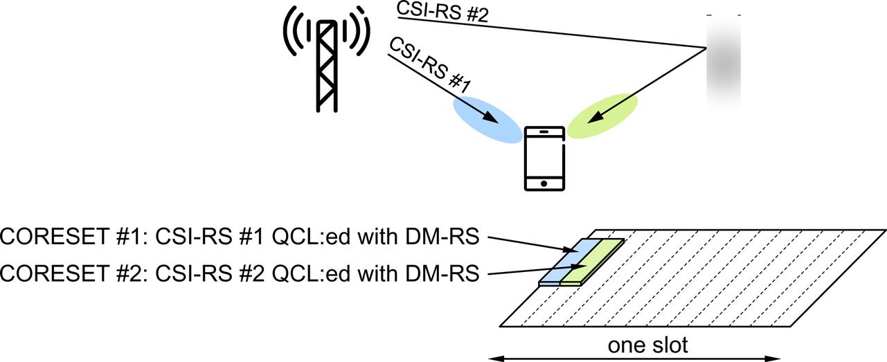
Related to channel estimation are, as has been discussed for other channels, the quasi-colocation relations applicable to the reference signals. If the device knows that two reference signals are quasi-collocated, this knowledge can be exploited to improve the channel estimation and, more importantly for the PDCCH, to manage different reception beams at the device (see Chapter 12 for a detailed discussion on beam management and spatial quasi-colocation). To handle this, each CORESET can be configured with a transmission configuration indication (TCI) state, that is, providing information of the antenna ports with which the PDCCH antenna ports are quasi-colocated. If the device is a certain CORESET spatially colocated with a certain CSI-RS, the device can determine which reception is appropriate when attempting to receive PDCCHs in this CORESET, as illustrated in Fig. 10.7. In this example, two CORESETs have been configured in the device, one CORESET with spatial QCL between DM-RS and CSI-RS #1, and one CORESET with spatial QCL between DM-RS and CSI-RS #2. Based on CSI-RS measurements, the device has determined the best reception beam for each of the two CSI-RS:es. When monitoring CORESET #1 for possible PDCCH transmissions, the device knows the spatial QCL relation and uses the appropriate reception beam (similarly for CORESET #2). In this way, the device can handle multiple reception beams as part of the blind decoding framework.
If no quasi-colocation is configured for a CORESET the device assumes the PDCCH candidates to be quasi-colocated with the SS block with respect to delay spread, Doppler spread, Doppler shift, average delay, and spatial Rx parameters. This is a reasonable assumption as the device has been able to receive and decode the PBCH in order to access the system.
10.1.3 Blind Decoding and Search Spaces
As described above, different DCI formats can be used for transmission on a PDCCH and the format used is a priori unknown to the device. Therefore, the device needs to blindly detect the DCI format. In LTE, the format was tightly coupled to the DCI size and monitoring for a certain DCI format in most cases implied monitoring for a new DCI size.
In NR, the coupling between DCI formats and DCI sizes is less pronounced. Different formats could still have different DCI sizes, but several formats share the same DCI size. This allows adding more formats in the future without increasing the number of blind decodings. An NR device needs to monitor for up to four different DCI sizes; one size used for the fallback DCI formats, one for downlink scheduling assignments, and (unless the uplink downlink non-fallback formats are size-aligned) one for uplink scheduling grants. In addition, a device may need to monitor for slot-format indication and preemption indication using a fourth size, depending on the configuration.
The CCE structure described in the previous section helps in reducing the number of blind decoding attempts but is not sufficient. Hence, it is required to have mechanisms to limit the number of PDCCH candidates that the device is supposed to monitor. Clearly, from a scheduling point of view, restrictions in the allowed aggregations are undesirable as they may reduce the scheduling flexibility and require additional processing at the transmitter side. At the same time, requiring the device to monitor all possible CCE aggregations in all configured CORESETs is not attractive from a device-complexity point of view. To impose as few restrictions as possible on the scheduler while at the same time limiting the maximum number of blind decoding attempts in the device, NR defines so-called search spaces. A search space is a set of candidate control channels formed by CCEs at a given aggregation level, which the device is supposed to attempt to decode. As there are multiple aggregation levels a device can have multiple search spaces. There can be multiple search spaces using the same CORESET and, as already described, there can be multiple CORESETs configured for a device. A device is not supposed for PDCCH outside its active bandwidth part, which follows from the overall purpose of a bandwidth part. Furthermore, the monitoring instance of a search space is configurable as illustrated in Fig. 10.8.
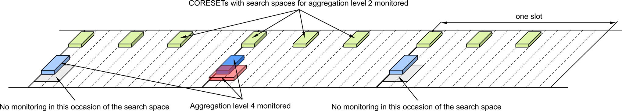
At a configured monitoring occasion for a search space, the devices will attempt to decode the candidate PDCCHs for that search space. Five different aggregation levels corresponding to 1, 2, 4, 8, and 16 CCEs, respectively, can be configured. The highest aggregation level, 16, is not supported in LTE and was added to NR in case of extreme coverage requirements. The number of PDCCH candidates can be configured per search space (and thus also per aggregation level). Hence NR has a more flexible way of spending the blind decoding attempts across aggregation levels than LTE, where the number of blind decodes at each aggregation level was fixed. This is motivated by the wider range of deployments expected for NR. For example, in a small-cell scenario the highest aggregation levels may not be used, and it is better to spend the limited number of blind decoding attempts the device is dimensioned for on the lower aggregation levels than on blind decoding on an aggregation level that is never used.
Upon attempting to decode a candidate PDCCH, the content of the control channel is declared as valid for this device if the CRC checks and the device processes the information (scheduling assignment, scheduling grants, etc.). If the CRC does not check, the information is either subject to uncorrectable transmission errors or intended for another device and in either case the device ignores that PDCCH transmission.
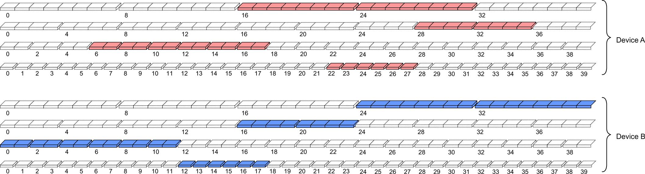
The network can only address a device if the control information is transmitted on a PDCCH formed by the CCEs in one of the device’s search spaces. For example, device A in Fig. 10.9 cannot be addressed on a PDCCH starting at CCE number 20, whereas device B can. Furthermore, if device A is using CCEs 16–23, device B cannot be addressed on aggregation level 4 as all CCEs in its level-4 search space are blocked by use for other devices. From this it can be intuitively understood that for efficient utilization of the CCEs in the system, the search spaces should differ between devices. Each device in the system can therefore have one or more device-specific search spaces configured. As a device-specific search space is typically smaller than the number of PDCCHs the network could transmit at the corresponding aggregation level, there must be a mechanism determining the set of CCEs in a device-specific search space.
One possibility would be to let the network configure the device-specific search space in each device, similar to the way the CORESETs are configured. However, this would require explicit signaling to each of the devices and possibly reconfiguration at handover. Instead, the device-specific search spaces for PDCCH are defined without explicit signaling through a function of the device identity unique in the cell, that is, the C-RNTI. Furthermore, the set of CCEs the device should monitor for a certain aggregation level also varies as a function of time to avoid two devices constantly blocking each other. If they collide at one time instant, they are not likely to collide at the next time instant. In each of these search spaces, the device is attempting to decode the PDCCHs using the device-specific C-RNTI identity.2 If valid control information is found, for example, a scheduling grant, the device acts accordingly.
However, there is also information intended for a group of devices. Furthermore, as part of the random-access procedure, it is necessary to transmit information to a device before it has been assigned a unique identity. These messages are scheduled with different predefined RNTIs, for example, the SI-RNTI for scheduling system information, the P-RNTI transmission of a paging message, the RA-RNTI for transmission of the random-access, and TPC-RNTI for uplink power control response. Other examples are the INT-RNTI used for preemption indication and the SFI-RNTI used for conveying slot-related information. These types of information cannot rely on a device-specific search space as different devices would monitor different CCEs despite the message being intended for all of them. Hence, NR also defines common search spaces.3 A common search space is similar in structure to a device-specific search space with the difference that the set of CCEs is predefined and hence known to all devices, regardless of their own identity.
The number of blind decoding attempts depends on the subcarrier spacing (and hence the slot duration). For 15/30/60/120 kHz subcarrier spacing, up to 44/36/22/20 blind decoding attempts per slot can be supported across all DCI payload sizes—a number selected to offer a good tradeoff between device complexity and scheduling flexibility. However, the number of blind decoded is not the only measure of complexity but also channel estimation needs to be accounted for. The number of channel estimates for subcarrier spacings of 15/30/60/120 kHz has been limited to 56/56/48/32 CCEs across all CORESETs in a slot. Depending on the configuration, the number of PDCCH candidate may be limited either by the number of blind decodes, or by the number of channel estimates. Finally, to limit the device complexity, a “3+1” DCI size budget is defined, meaning that a device at most monitors three different DCI sizes using the C-RNTI (and hence being time-critical) and one DCI size using other RNTIs (and hence less time critical).
In the case of carrier aggregation, the general blind decoding operation described above is applied per component carrier. The total number of channel estimates and blind decoding attempts is increased compared to the single carrier case, but not in direct proportion to the number of aggregated carriers.
10.1.4 Downlink Scheduling Assignments—DCI Formats 1–0 and 1–1
Having described the transmission of DCI on PDCCH, the detailed contents of the control information can be discussed, starting with the downlink scheduling assignments. Downlink scheduling assignments use DCI format 1–1, the non-fallback format, or DCI format 1–0, also known as the fallback format.
The non-fallback format 1–1 supports all NR features. Depending on the features that are configured in the system, some information fields may or may not be present. For example, if carrier aggregation is not configured, there is no need to include carrier-aggregation-related information in the DCI. Hence the DCI size for format 1–1 depends on the overall configuration, but as long as the device knows which features are configured, it also knows the DCI size and blind detection can be performed.
The fallback format 1–0 is smaller in size, supports a limited set of NR functionality, and the set of information fields is in general not configurable, resulting in a (more or less) fixed DCI size. One use case of the fallback format is to handle periods of uncertainty in the configuration of a device as the exact time instant when a device applies the configuration information is not known to the network, for example due to transmission errors. Another reason for using the fallback DCI is to reduce control signaling overhead. In many cases the fallback format provides sufficient flexibility for scheduling smaller data packets.
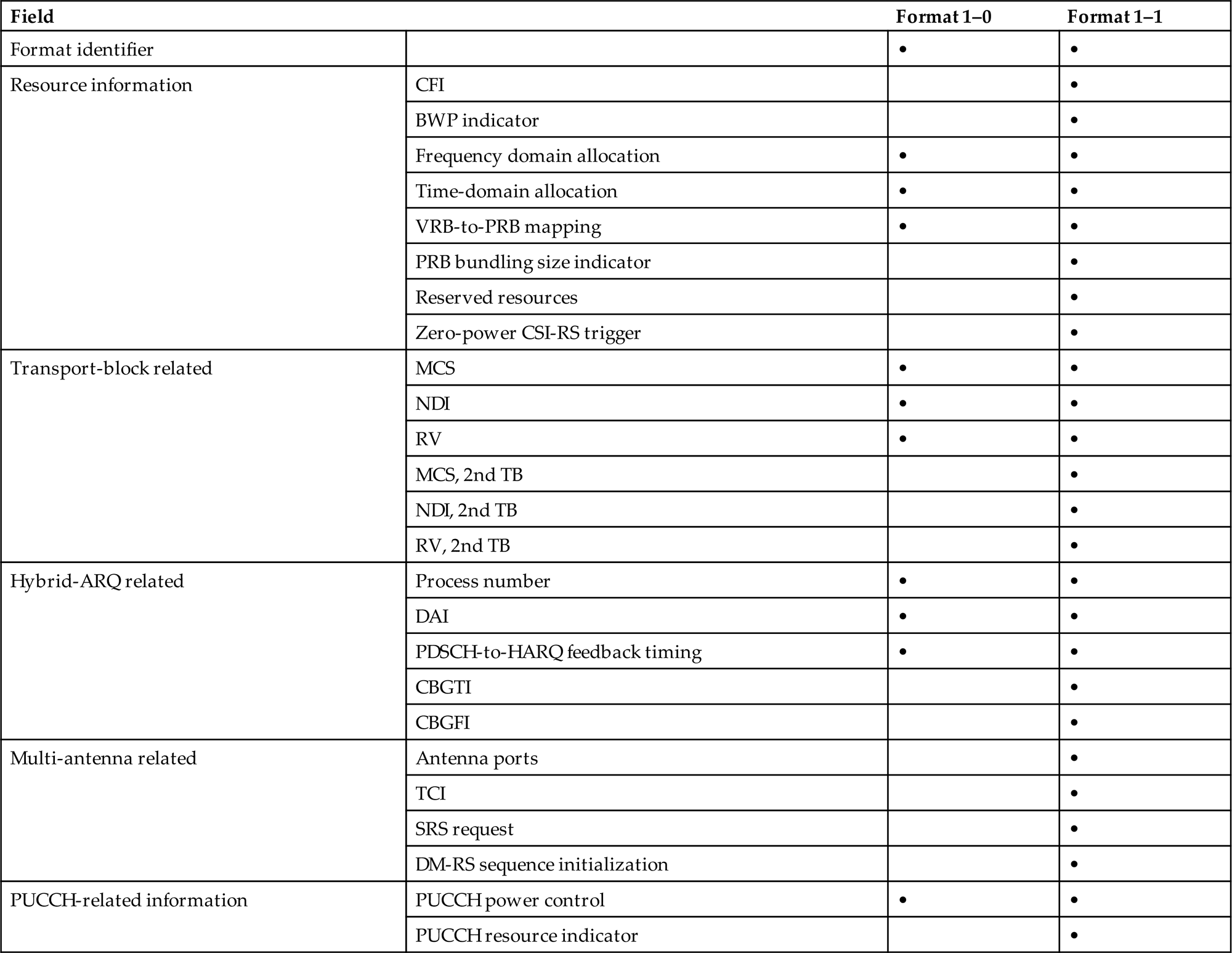
Parts of the contents are the same for the different DCI formats, as seen in Table 10.1, but there are also differences due to the different capabilities. The information in the DCI formats used for downlink scheduling can be organized into different groups, with the fields present varying between the DCI formats. The content of DCI formats for downlink scheduling assignments is described below:
- • Identifier of DCI format (1 bit). This is a header to indicate whether the DCI is a downlink assignment or an uplink grant, which is important in case the payload sizes of multiple DCI formats are aligned and the size cannot be used to differentiate the DCI formats (one example hereof is the fallback formats 0–0 and 1–0 which are of equal size).
- • Resource information, consisting of:
- • Carrier indicator (0 or 3 bit). This field is present if cross-carrier scheduling is configured and is used to indicate the component carrier the DCI relates to. The carrier indicator is not present in the fallback DCI for example used for common signaling to multiple devices, as not all devices may be configured with (or capable of) carrier aggregation.
- • Bandwidth-part indicator (0–2 bit), used to activate one of up to four bandwidth parts configured by higher-layer signaling. Not present in the fallback DCI.
- • Frequency-domain resource allocation. This field indicates the resource blocks on one component carrier upon which the device should receive the PDSCH. The size of the field depends on the size of the bandwidth and on the resource allocation type, type 0 only, type 1 only, or dynamic switching between the two as discussed in Section 10.1.10. Format 1–0 supports resource allocation type 1 only as the full flexibility in resource allocation is not needed in this case.
- • Time-domain resource allocation (1–4 bit). This field indicates the resource allocation in the time domain as described in Section 10.1.11
- • VRB-to-PRB mapping (0 or 1 bit) to indicate whether interleaved or non-interleaved VRB-to-PRB mapping should be used as described in Section 9.9. Only present for resource allocation type 1.
- • PRB size indicator (0 or 1 bit), used to indicate the PDSCH bundling size as described in Section 9.9.
- • Reserved resources (0–2 bit), used to indicate to the device if the reserved resources can be used for PDSCH or not as described in Section 9.10.
- • Zero-power CSI-RS trigger (0–2 bit), see Section 8.1 for a discussion on CSI reference signals.
- • Transport-block-related information:
- • Modulation-and-coding scheme (5 bit), used to provide the device with information about the modulation scheme, the code rate, and the transport-block size, as described further below.
- • New-data indicator (1 bit), used to clear the soft buffer for initial transmissions as discussed in Section 13.1.
- • Redundancy version (2 bit) (see Section 13.1).
- • If a second transport block is present (only if more than four layers of spatial multiplexing are supported in DCI format 1–1), the three fields above are repeated for the second transport block.
- • Hybrid-ARQ-related information:
- • Hybrid-ARQ process number (4 bit), informing the device about the hybrid-ARQ process to use for soft combining.
- • Downlink assignment index (DAI, 0, 2, or 4 bit), only present in the case of a dynamic hybrid-ARQ codebook as described in Section 13.1.5. DCI format 1–1 supports 0, 2, or 4 bits, while DCI format 1–0 uses 2 bits.
- • HARQ feedback timing (3 bit), providing information on when the hybrid-ARQ acknowledgment should be transmitted relative to the reception of the PDSCH.
- • CBG transmission indicator (CBGTI, 0, 2, 4, 6, or 8 bit), indicating the code block groups retransmitted as described in Section 13.1.2. Only present in DCI format 1–1 and only if CBG retransmissions are configured.
- • CBG flush information (CBGFI, 0–1 bit), indicating soft buffer flushing as described in Section 13.1.2. Only present in DCI format 1–1 and only if CBG retransmissions are configured.
- • Multi-antenna-related information (present in DCI format 1–1 only):
- • Antenna ports (4–6 bit), indicating the antenna ports upon which the data are transmitted as well as antenna ports scheduled for other users as discussed in Chapters 9 and 11.
- • Transmission configuration indication (TCI, 0 or 3 bit), used to indicate the QCL relations for downlink transmissions as described in Chapter 12.
- • SRS request (2 bit), used to request transmission of a sounding reference signal as described in Section 8.3.
- • DM-RS sequence initialization (0 or 1 bit), used to select between two preconfigured initialization values for the DM-RS sequence.
- • PUCCH-related information:
- • PUCCH power control (2 bit), used to adjust the PUCCH transmission power.
- • PUCCH resource indicator (3 bit), used to select the PUCCH resource from a set of configured resources (see Section 10.2.7).
Table 10.1
10.1.5 Uplink Scheduling Grants—DCI Formats 0–0 and 0–1
Uplink scheduling grants use one of DCI formats 0–1, the non-fallback format, or DCI format 0–0, also known as the fallback format. The reason for having both a fallback and a non-fallback format is the same as for the downlink, namely to handle uncertainties during RRC reconfiguration and to provide a low-overhead format for transmissions not exploiting all uplink features. As for the uplink, the information fields present in the non-fallback format depend on the features that are configured.
The DCI sizes for the uplink DCI format 0–1 and downlink DCI format 1–1 are aligned with padding added to the smaller of the two in order to reduce the number of blind decodes.
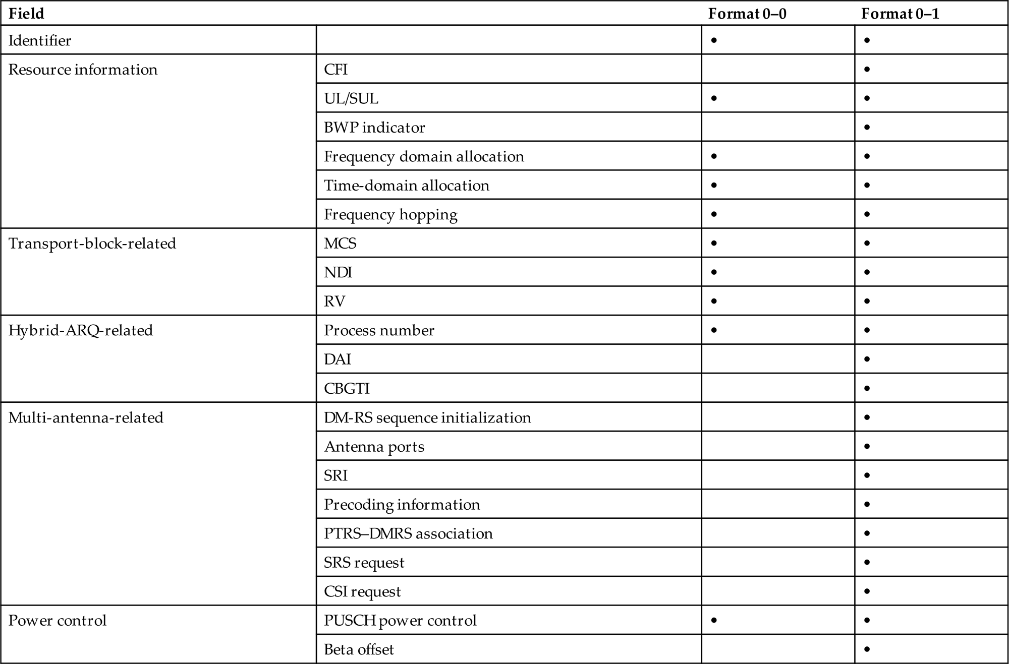
Parts of the contents are the same for the different DCI formats, as seen in Table 10.2, but there are also differences due to the different capabilities. The information in the DCI formats used for uplink scheduling can be organized into different groups, with the fields present varying between the DCI formats. The content of DCI formats 0–1 and 0–0 is described below:
- • Identifier of DCI format (1 bit), a header to indicate whether the DCI is a downlink assignment or an uplink grant.
- • Resource information, consisting of:
- • Carrier indicator (0 or 3 bit). This field is present if cross-carrier scheduling is configured and is used to indicate the component carrier the DCI relates to. The carrier indicator is not present in DCI format 0–0.
- • UL/SUL indicator (0 or 1 bit), used to indicate whether the grant relates to the supplementary uplink or the ordinary uplink (see Section 7.7). Only present if a supplementary uplink is configured as part of the system information.
- • Bandwidth-part indicator (0–2 bit), used to activate one of up to four bandwidth parts configures by higher-layer signaling. Not present in DCI format 0–0.
- • Frequency-domain resource allocation. This field indicates the resource blocks on one component carrier upon which the device should transmit the PUSCH. The size of the field depends on the size of the bandwidth and on the resource allocation type, type 0 only, type 1 only, or dynamic switching between the two as discussed in Section 10.1.10. Format 0–0 supports resource allocation type 1 only.
- • Time-domain resource allocation (0–4 bit). This field indicates the resource allocation in the time domain as described in Section 10.1.11.
- • Frequency-hopping flag (0 or 1 bit), used to handle frequency hopping for resource allocation type 1.
- • Transport-block-related information:
- • Modulation-and-coding scheme (5 bit), used to provide the device with information about the modulation scheme, the code rate, and the transport-block size, as described further below.
- • New-data indicator (1 bit), used to indicate whether the grant relates to retransmission of a transport block or transmission of a new transport block.
- • Redundancy version (2 bit).
- • Hybrid-ARQ-related information:
- • Hybrid ARQ process number (4 bit), informing the device about the hybrid-ARQ process to (re)transmit.
- • Downlink assignment index (DAI), used for handling of hybrid-ARQ codebooks in case of UCI transmitted on PUSCH. Not present in DCI format 0–0.
- • CBG transmission indicator (CBGTI, 0, 2, 4, or 6 bit), indicating the code block groups to retransmit as described in Section 13.1. Only present in DCI format 0–1 and only if CBG retransmissions are configured.
- • Multi-antenna-related information (present in DCI format 1–1 only):
- • DMRS sequence initialization (1 bit), used to select between two preconfigured initialization values for the DM-RS sequence.
- • Antenna ports (2–5 bit), indicating the antenna ports upon which the data are transmitted as well as antenna ports scheduled for other users as discussed in Chapters 9 and 11.
- • SRS resource indicator (SRI), used to determine the antenna ports and uplink transmission beam to use for PUSCH transmission as described in Section 11.3. The number of bits depends on the number of SRS groups configured and whether codebook-based or non-codebook-based precoding is used.
- • Precoding information (0–6 bit), used to select the precoding matrix W and the number of layers for codebook-based precoding as described in Section 11.3. The number of bits depends on the number of antenna ports and the maximum rank supported by the device.
- • PTRS-DMRS association (0 or 2 bit), used to indicate the association between the DM-RS and PT-RS ports.
- • SRS request (2 bit), used to request transmission of a sounding reference signal as described in Section 8.3.
- • CSI request (0–6 bit), used to request transmission of a CSI report as described in Section 8.1.
- • Power-control-related information:
- • PUSCH power control (2 bit), used to adjust the PUSCH transmission power.
- • Beta offset (0 or 2 bit), used to control the amount of resources used by UCI on PUSCH in case dynamic beta offset signaling is configured for DCI format 0–1 as discussed in Section 10.2.8.
Table 10.2
10.1.6 Slot Format Indication—DCI Format 2–0
DCI format 2–0, if used, is used to signal the slot format information (SFI) to the device as discussed in Section 7.8.3. The SFI is transmitted using the regular PDCCH structure and using the SFI-RNTI, common to multiple devices. To assist the device in the blind decoding process, the device is configured with information about the up to two PDCCH candidates upon which the SFI can be transmitted.
10.1.7 Preemption Indication—DCI Format 2–1
DCI format 2–1 is used to signal the preemption indicator to the device. It is transmitted using the regular PDCCH structure, using the INT-RNTI which can be common to multiple devices. The details and usage of the preemption indicator are discussed in Section 14.1.2.
10.1.8 Uplink Power Control Commands—DCI Format 2–2
As a complement to the power-control commands provided as part of the downlink scheduling assignments and the uplink scheduling grants, there is the potential to transmit a power-control command using DCI format 2–2. The main motivation for DCI format 2–2 is to support power control for semipersistent scheduling. In this case there is no dynamic scheduling assignment or scheduling grant which can include the power control information for the PUCCH and PUSCH, respectively. Consequently, another mechanism is needed and DCI format 2–2 fulfills this need. The power-control message is directed to a group of devices using an RNTI specific for that group and each device is configured with the power control bits in the join message it should follow. DCI format 2–2 is aligned with the size of DCI formats 0–0/1–0 to reduce the blind decoding complexity.
10.1.9 SRS Control Commands—DCI Format 2–3
DCI format 2–3 is used for power control of uplink sounding reference signals for devices which have not coupled the SRS power control to the PUSCH power control, either because independent control is desirable or because the device is configured without PUCCH and PUSCH. The structure is similar to DCI format 2–2, but with the possibility to, for each device, configure two bits for SRS request in addition to the two power control bits. DCI format 2–2 is aligned with the size of DCI formats 0–0/1–0 to reduce the blind decoding complexity.
10.1.10 Signaling of Frequency-Domain Resources
To determine the frequency-domain resources to transmit or receive upon, two fields are of interest: the resource-block allocation field and the bandwidth part indicator.
The resources allocation fields determine the resources blocks in the active bandwidth part upon which data are transmitted. There are two different possibilities for signaling the resources-block allocation, type 0 and type 1, both inherited from LTE where they are known as downlink resource allocation type 0 and type 2. In LTE, the resource-block allocation signaled the allocation across the carrier. However, in NR the indication is for the active bandwidth part.
Type 0 is a bitmap-based allocation scheme. The most flexible way of indicating the set of resource blocks the device is supposed to receive the downlink transmission upon is to include a bitmap with size equal to the number of resource blocks in the bandwidth part. This would allow for an arbitrary combination of resource blocks to be scheduled for transmission to the device but would, unfortunately, also result in a very large bitmap for the larger bandwidths. For example, in the case of a bandwidth part of 100 resource blocks, the downlink PDCCH would require 100 bits for the bitmap alone, to which the other pieces of information need to be added. Not only would this result in a large control-signaling overhead, but it could also result in downlink coverage problems as more than 100 bits in one OFDM symbol correspond to a data rate exceeding 1.4 Mbit/s for 15 kHz subcarrier spacing and even higher for the higher subcarrier spacings. Consequently, there is a need to reduce the bitmap size while keeping sufficient allocation flexibility. This can be achieved by pointing not to individual resource blocks in the frequency domain, but to groups of contiguous resource blocks, as shown in at the top of Fig. 10.10. The size of such a resource-block group is determined by the size of the bandwidth part. Two different configurations are possible for each size of the bandwidth parts, possibly resulting in different resource-block-group sizes for a given size of the bandwidth part.
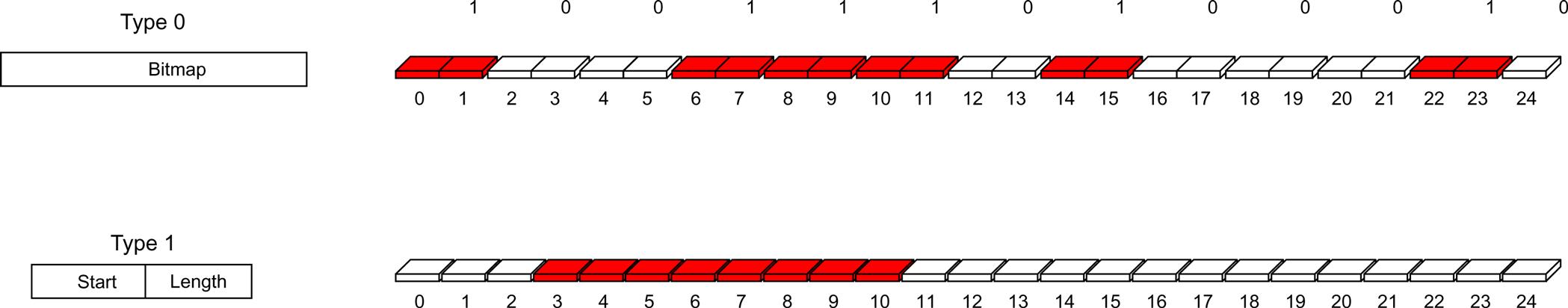
Resource allocation type 1 does not rely on a bitmap. Instead, it encodes the resource allocation as a start position and length of the resource-block allocation. Thus, it does not support arbitrary allocations of resource blocks but only frequency-contiguous allocations, thereby reducing the number of bits required for signaling the resource-block allocation.
The resource allocation scheme to use is configured according to three alternatives: type 0, type 1, or dynamic selection between the two using a bit in the DCI. For the fallback DCIs, only resource block allocation type 1 is supported as a small overhead is more important than the flexibility to configure non-contiguous resources.
Both resource-allocation types refer to virtual resource blocks (see Section 7.3 for a discussion of resource-block types). For resource-allocation types 0, a non-interleaved mapping from virtual to physical resource blocks is used, meaning that the virtual resource blocks are directly mapped to the corresponding physical resource blocks. For resource-allocation type 1, on the other hand, both interleaved and non-interleaved mapping is supported. The VRB-to-PRB mapping bit (if present, downlink only) indicates whether the allocation signaling uses interleaved or non-interleaved mapping.
Returning to the bandwidth part indicator, this field is used to switch the active bandwidth part. It can either point to the current active bandwidth part, or to another bandwidth part to activate. If the field points to the current active bandwidth part, the interpretation of the DCI content is straightforward—the resource allocation applies to the current active bandwidth part as described above.
However, if the bandwidth part indicator points to a different bandwidth part than the active bandwidth part, the handling becomes more intricate. Many transmission parameters in general are configured per bandwidth part. The DCI payload size therefore may differ between different bandwidth parts. The frequency-domain resource allocation field is an obvious example; the larger the bandwidth part, the larger the number of bits for frequency-domain resource allocation. At the same time, the DCI sizes assumed when performing blind detection were determined by the currently active bandwidth part, not the bandwidth part to which the bandwidth part index points. Requiring the device to performing blind detection of multiple DCI sizes matching all possible bandwidth part configurations would be too complex. Hence, the DCI information obtained under the assumption of the DCI format being given by the currently active bandwidth part must be transformed to the new bandwidth part, which may have not only a different size in general, but also be configured with a different set of transmission parameters, for example TCI states which are configured per bandwidth part. The transformation is done using padding/truncation for each DCI field to match the requirements of the targeted bandwidth part. Once this is done, the bandwidth part pointed to by the bandwidth part indicator becomes the new active bandwidth part and the scheduling grant is applied to this bandwidth part. Similar transformation is sometimes required for DCI formats 0–0 and 1–0 in situations where the “3+1” DCI size budget otherwise would be violated.
10.1.11 Signaling of Time-Domain Resources
The time-domain allocation for the data to be received or transmitted is dynamically signaled in the DCI, which is useful as the part of a slot available for downlink reception or uplink transmission may vary from slot to slot as a result of the use of dynamic TDD or the amount of resources used for uplink controls signaling. Furthermore, the slot in which the transmission occurs also needs to be signaled as part of the time-domain allocation. Although the downlink data in many cases are transmitted in the same slot as the corresponding assignment, this is frequently not the case for uplink transmissions.
One approach would be to separately signal the slot number, the starting OFDM symbol, and the number of OFDM symbols used for transmission or reception. However, as this would result in an unnecessarily large number of bits, NR has adopted an approach based on configurable tables. The time-domain allocation field in the DCI is used as an index into an RRC-configured table from which the time-domain allocation is obtained, as illustrated in Fig. 10.11.
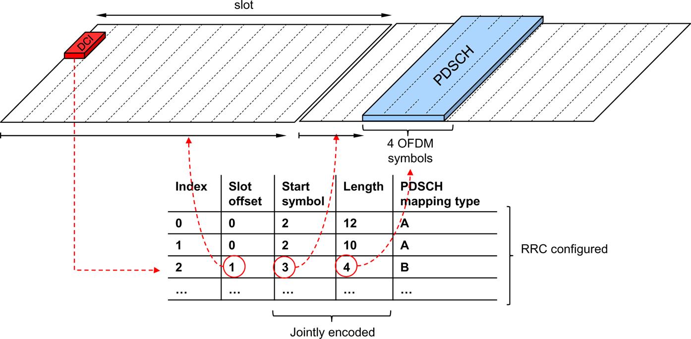
There is one table for uplink scheduling grants and one table for downlink scheduling assignments. Up to 16 rows can be configured where each row contains:
- • A slot offset, that is, the slot relative to the one where the DCI was obtained. For the downlink, slot offsets from 0 to 3 are possible, while for the uplink slot offsets from 0 to 7 can be used. The larger uplink range can be motivated by the need for scheduling uplink transmissions further into the future for coexistence with (primarily) LTE TDD.
- • The first OFDM symbol in the slot where the data are transmitted.
- • The duration of the transmission in number of OFDM symbols in the slot. Not all combinations of start and length fit within one slot, for example, starting at OFDM symbol 12 and transmit during five OFDM symbols obviously results in crossing the slot boundary and represents an invalid combination. Therefore, the start and length are jointly encoded to cover only the valid combinations (although in Fig. 10.11 they are shown as two separate columns for illustrative reasons).
- • For the downlink, the PDSCH mapping type, that is, the DM-RS location as described in Section 9.11, is also part of the table. This provides more flexibility compared to separately indicating the mapping type.
It is also possible to configure slot aggregation, that is, a transmission where the same transport block is repeated across up to eight slots. However, this is not part of the dynamic signaling using a table but is a separate RRC configuration. Slot aggregation is primarily a tool to handle coverage-challenged deployments and thus there is less need for a fully dynamic scheme.
10.1.12 Signaling of Transport-Block Sizes
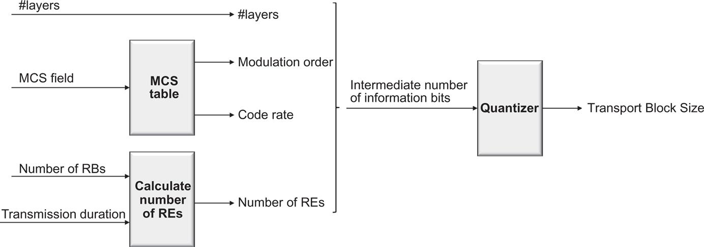
Proper reception of a downlink transmission requires, in addition to the set of resource blocks, knowledge about the modulation scheme and the transport-block size, information (indirectly) provided by the 5-bit MCS field. In principle, a similar approach as in LTE, namely to tabulate the transport block size as a function of the MCS field and the resource-block allocation would be possible. However, the significantly larger bandwidths supported in NR, together with a wide range of transmission durations and variations in the overhead depending on other features configured such as CSI-RS, would result in a large number of tables required to handle the large dynamic range in terms of transport block sizes. Such a scheme may also require modifications whenever some of these parameters change. Therefore, NR opted for a formula-based approach combined with a table for the smallest transport-block sizes instead of a purely table-based scheme to achieve the necessary flexibility.
The first step is to determine the modulation scheme and code rate from the MCS field. This is done using one of two tables, one table if 256QAM is not configured and another table if 256QAM is configured. Of the 32 combinations of the 5-bit MCS fields, 29 are used to signal the modulation-and-coding scheme, whereas three are reserved, the purpose of which is described later. Each of the 29 modulation-and-coding scheme entries represents a particular combination of modulation scheme and channel-coding rate or, equivalently, a certain spectral efficiency measured in the number of information bits per modulation symbol, ranging from approximately 0.2–5.5 bit/s/Hz. For devices configured with support for 256QAM, four of the 32 combinations are reserved and the remaining 28 combinations indicate a spectral efficiency in the range 0.2–7.4 bit/s/Hz.
Up to this point, the NR scheme is similar to the one used for LTE. However, to obtain a more flexible scheme, the following steps differ compared to LTE.
Given the modulation order, the number of resource blocks scheduled, and the scheduled transmission duration, the number of available resource elements can be computed. From this number the resource elements used for DM-RS are subtracted. A constant, configured by higher layers and modeling the overhead by other signals such as CSI-RS or SRS is also subtracted. The resulting estimate of resource elements available for data is then, together with the number of transmission layers, the modulation order, and the code rate obtained from the MCS, used to calculate an intermediate number of information bits. This intermediate number is then quantized to obtain the final transport block size while at the same time ensuring byte-aligned code blocks, and that no filler bits are needed in the LDPC coding. The quantization also results in the same transport block size being obtained, even if there are small variations in the amount of resources allocated, a property that is useful when scheduling retransmissions on a different set of resources than the initial transmission.
Returning to the three or four reserved combinations in the modulation-and-coding field mentioned at the beginning of this section, those entries can be used for retransmissions only. In the case of a retransmission, the transport-block size is, by definition, unchanged and fundamentally there is no need to signal this piece of information. Instead, the three or four reserved values represent the modulation scheme—QPSK, 16QAM, 64QAM, or (if configured) 256QAM—which allows the scheduler to use an (almost) arbitrary combination of resource blocks for the retransmission. Obviously, using any of the three or four reserved combinations assumes that the device properly received the control signaling for the initial transmission; if this is not the case, the retransmission should explicitly indicate the transport-block size.
The derivation of the transport-block size from the modulation-and-coding scheme and the number of scheduled resource blocks is illustrated in Fig. 10.12.
10.2 Uplink
Similar to LTE, there is also a need for uplink L1/L2 control signaling to support data transmission on downlink and uplink transport channels. Uplink L1/L2 control signaling consists of:
- • Hybrid-ARQ acknowledgments for received DL-SCH transport blocks;
- • Channel-state information (CSI) related to the downlink channel conditions, used to assist downlink scheduling, including multi-antenna and beamforming schemes; and
- • Scheduling requests, indicating that a device needs uplink resources for UL-SCH transmission.
There is no UL-SCH transport-format information included in the uplink transmission. As mentioned in Section 6.4.4, the gNB is in complete control of the uplink UL-SCH transmissions and the device always follows the scheduling grants received from the network, including the UL-SCH transport format specified in those grants. Thus, the network knows the transport format used for the UL-SCH transmission in advance and there is no need for any explicit transport-format signaling on the uplink.
The physical uplink control channel (PUCCH) is the basis for transmission of uplink control. In principle, the UCI could be transmitted on the PUCCH regardless of whether the device is transmitting data on the PUSCH. However, especially if the uplink resources for the PUSCH and the PUCCH are on the same carrier (or, to be more precise, use the same power amplifier) but widely separated in the frequency domain, the device may need a relatively large power back-off to fulfill the spectral emission requirements with a corresponding impact on the uplink coverage. Hence, similarly to LTE, NR supports UCI on PUSCH as the basic way of handling simultaneous transmission of data and control. Thus, if the device is transmitting on the PUSCH the UCI is multiplexed with data on the granted resources instead of being transmitted on the PUCCH. Simultaneous PUSCH and PUCCH is not part of release 15 but may be introduced in a later release.
Beamforming can be applied to the PUCCH. This is realized by configuring one or more spatial relations between the PUCCH and downlink signals such as CSI-RS or SS block. In essence, such a spatial relation means that the device can transmit the uplink PUCCH using the same beam as it used for receiving the corresponding downlink signal. For example, if the spatial relation between PUCCH and SS block is configured, the device will transmit PUCCH using the same beam as it used for receiving the SS block. Multiple spatial relations can be configured and MAC control elements used to indicate which one to use.
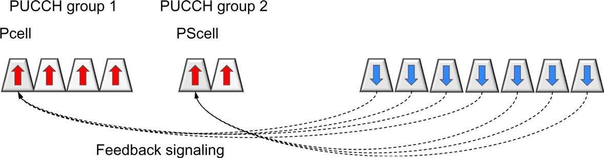
In the case of carrier aggregation, the uplink control information is transmitted on the primary cell as a baseline. This is motivated by the need to support asymmetric carrier aggregation with the number of downlink carriers supported by a device that is unrelated to the number of uplink carriers. For a large number of downlink component carriers, a single uplink carrier may carry a large number of acknowledgments. To avoid overloading a single carrier, it is possible to configure two PUCCH groups where feedback relating to the first group is transmitted in the uplink of the PCell and feedback relating to the other group of carriers is transmitted on the primary second cell (PSCell), as illustrated in Fig. 10.13.
In the following section, the basic PUCCH structure and the principles for PUCCH control signaling are described, followed by control signaling on PUSCH.
10.2.1 Basic PUCCH Structure
Uplink control information can be transmitted on PUCCH using several different formats.
Two of the formats, 0 and 2, are sometimes referred to as short PUCCH formats, as they occupy at most two OFDM symbols. In many cases the last one or two OFDM symbols in a slot are used for PUCCH transmission, for example, to transmit a hybrid-ARQ acknowledgment of the downlink data transmission. The short PUCCH formats include:
- • PUCCH format 0, capable of transmitting at most two bits and spanning one or two OFDM symbols. This format can, for example, be used to transmit a hybrid-ARQ acknowledgment of a downlink data transmission, or to issue a scheduling request.
- • PUCCH format 2, capable of transmitting more than two bits and spanning one or two OFDM symbols. This format can, for example, be used for CSI reports or for multi-bit hybrid-ARQ acknowledgments in the case of carrier aggregation or per-CBG retransmission.
Three of the formats, 1, 3, and 4, are sometimes referred to as long PUCCH formats as they occupy from 4 to 14 OFDM symbols. The reason for having a longer time duration than the previous two formats is coverage. If a duration of one or two OFDM symbols does not provide sufficient received energy for reliable reception, a longer time duration is necessary and one of the long PUCCH formats can be used. The long PUCCH formats include:
Since the PUSH uplink can be configured to use either OFDM or DFT-spread OFDM, one natural thought would be to adopt a similar approach for the PUCCH. However, to reduce the number of options to specify, this is not the case. Instead, the PUCCH formats are in general designed for low cubic metric, PUCCH format 2 being the exception and using pure OFDM only. Another choice made to simplify the overall design was to only support specification-transparent transmit diversity schemes. In other words, there is only a single antenna port specified for the PUCCH and if the device is equipped with multiple transmit antennas it is up to the device implementation how to exploit these antennas, for example by using some form of delay diversity. In the following, the detailed structure of each of these PUCCH formats will be described.
10.2.2 PUCCH Format 0
PUCCH format 0, illustrated in Fig. 10.14, is one of the short PUCCH formats and is capable of transmitting up to two bits. It is used for hybrid-ARQ acknowledgments and scheduling requests.
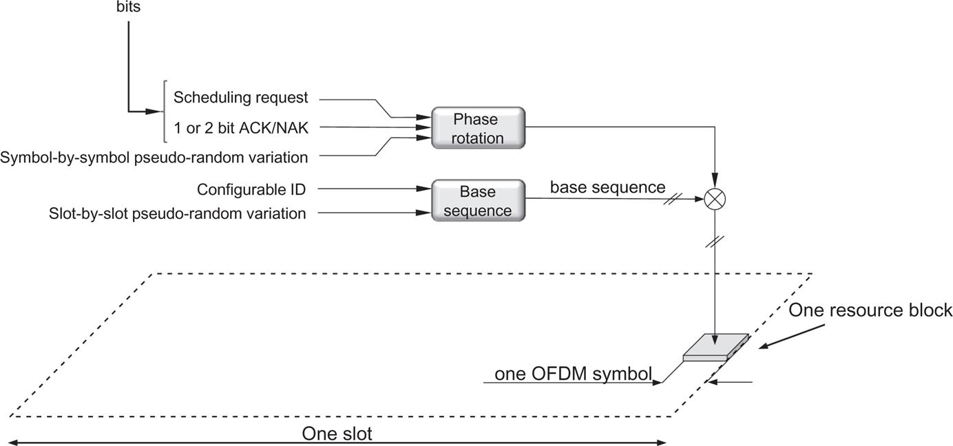
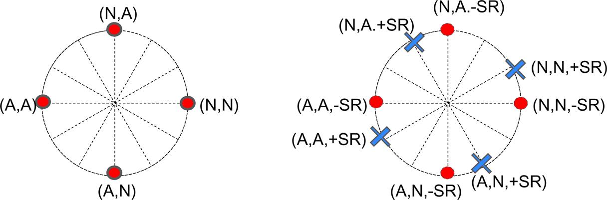
Sequence selection is the basis for PUCCH format 0. For the small number of information bits supported by PUCCH format 0, the gain from coherent reception is not that large. Furthermore, multiplexing information and reference signals in one OFDM symbol while maintaining a low cubic metric is not possible. Therefore, a different structure where the information bit(s) selects the sequence to transmit is used. The transmitted sequence is generated by different phase rotations of the same underlying length-12 base sequence, where the base sequences are the same base sequences defined for generating the reference signal in the case of DFT-preceded OFDM as described in Section 9.11.2. Thus, the phase rotation applied to the base sequence carries the information. In other words, the information selects one of several phase-rotated sequences.
Twelve different phase rotations are defined for the same base sequence, providing up to 12 different orthogonal sequences from each base sequence. A linear phase rotation in the frequency domain is equivalent to applying a cyclic shift in the time domain, hence, the term “cyclic shift” is sometimes used with an implicit reference to the time domain.
To maximize the performance, the phase rotations representing the different information bits are separated with 2π·6/12 and 2π·3/12 for one and two bits acknowledgments, respectively. In the case of a simultaneous scheduling request, the phase rotation is increased by 3π/12 for one acknowledgment bit and by 2π/12 for two bits, as illustrated in Fig. 10.15.
The phase rotation applied to a certain OFDM symbol carrying PUCCH format 0 depends not only on the information to be transmitted as already mentioned, but also on a reference rotation provided as part of the PUCCH resource allocation mechanism as discussed in Section 10.2.7. The intention with the reference rotation is to multiplex multiple devices on the same time–frequency resource. For example, two devices transmitting a single hybrid-ARQ acknowledgment can be given different reference phase rotations such that one device uses 0 and 2π·6/12, while the other device uses 2π·3/12 and 2π·9/12. Finally, there is also a mechanism for cyclic shift hopping where a phase offset varying between different slots is added. The offset is given by a pseudo-random sequence. The underlying reason is to randomize interference between different devices.
The base sequence to use can be configured per cell using an identity provided as part of the system information. Furthermore, sequence hopping, where the base sequence used varies on a slot-by-slot basis, can be used to randomize the interference between different cells. As seen from this description many quantities are randomized in order to mitigate interference.
PUCCH format 0 is typically transmitted at the end of a slot as illustrated in Fig. 10.14. However, it is possible to transmit PUCCH format 0 also in other positions within a slot. One example is frequently occurring scheduling requests (as frequent as every second OFDM symbol can be configured). Another example when this can be useful is to acknowledge a downlink transmission on a downlink carrier at a high carrier frequency and, consequently, a correspondingly higher subcarrier spacing and shorter downlink slot duration. This is a relevant scenario in the case of carrier aggregation and supplementary uplink, as discussed in Chapter 7. If low latency is important, the hybrid-ARQ acknowledgment needs to be fed back quickly after the end of the downlink slot, which is not necessarily at the end of the uplink slot if the subcarrier spacing differs between uplink and downlink.
In the case of two OFDM symbols used for PUCCH format 0, the same information is transmitted in both OFDM symbols. However, the reference phase rotation as well as the frequency-domain resources may vary between the symbols, essentially resulting in a frequency-hopping mechanism.
10.2.3 PUCCH Format 1
PUCCH format 1 is to some extent the long PUCCH counterpart of format 0. It is capable of transmitting up to two bits, using from 4 to 14 OFDM symbols, each one resource block wide in frequency. The OFDM symbols used are split between symbols for control information and symbols for reference signals to enable coherent reception. The number of symbols used for control information and reference signal, respectively, is a trade-off between channel-estimation accuracy and energy in the information part. Approximately half the symbols for reference symbols were found to be a good compromise for the payloads supported by PUCCH format 2.
The one or two information bits to be transmitted are BPSK or QPSK modulated, respectively, and multiplied by the same type of length-12 low-PAPR sequence as used for PUCCH format 0. Similar to format 0, sequence and cyclic shift hopping can be used to randomize interference. The resulting modulated length-12 sequence is block-wise spread with an orthogonal DFT code of the same length as the number of symbols used for the control information. The use of the orthogonal code in the time domain increases the multiplexing capacity as multiple devices having the same base sequence and phase rotation still can be separated using different orthogonal codes.
The reference signals are inserted using the same structure, that is, an unmodulated length-12 sequence is block-spread with an orthogonal sequence and mapped to the OFDM symbols used for PUCCH reference-signal transmission. Thus, the length of the orthogonal code, together with the number of cyclic shifts, determines the number of devices that can transmit PUCCH format 1 on the same resource. An example is shown in Fig. 10.16 where nine OFDM symbols are used for PUCCH transmission, four carrying the information and five used for reference signals. Hence, up to four devices, determined by the shorter of the codes for the information part, can share the same cyclic shift of the base sequence, and a set of resources for PUCCH transmission in this particular example. Assuming a cell-specific base sequence and six out of the 12 cyclic shifts being useful from a delay-spread perspective, this results in a multiplexing capacity of at most 24 devices on the same time–frequency resources.
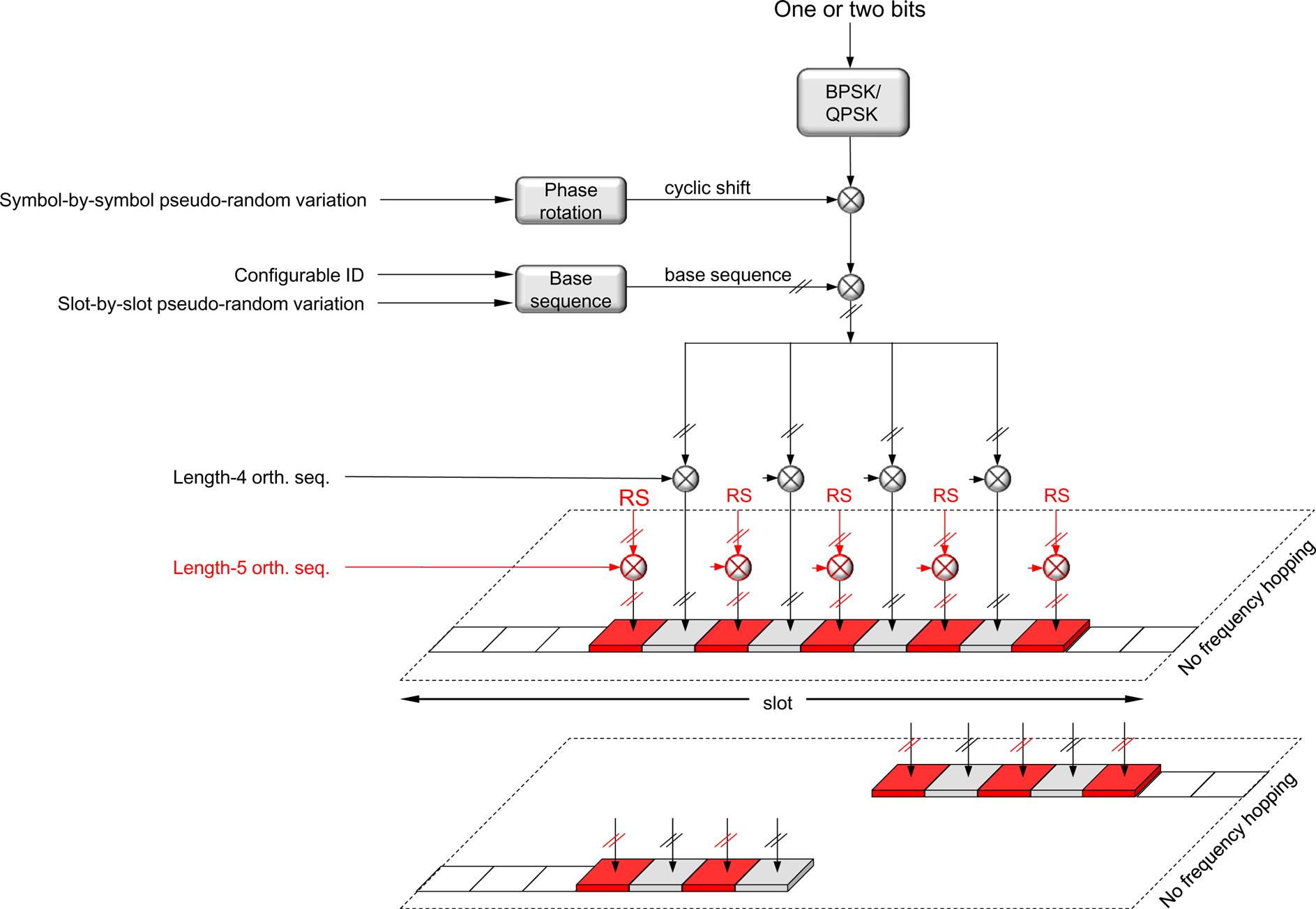
The longer transmission duration of the long PUCCH formats compared to a short single-symbol format opens the possibility for frequency hopping as a mean to achieve frequency diversity in a similar way as in LTE. However, unlike LTE, where hopping is always done at the slot boundary between the two slots used for PUCCH, additional flexibility is needed in NR as the PUCCH duration can vary depending on the scheduling decisions and overall system configuration. Furthermore, as the devices are supposed to transmit within their active bandwidth part only, hopping is typically not between the edges of the overall carrier bandwidth as in LTE. Therefore, whether to hop or not is configurable and determined as part of the PUCCH resource configuration. The position of the hop is obtained from the length of the PUCCH. If frequency hopping is enabled, one orthogonal block-spreading sequence is used per hop. An example is provided in Fig. 10.16 where, instead of a single set of length-4/length-5 orthogonal sequences, two sets of sequences length-2/length-2 and length-2/length-3, are used for the first and second hops, respectively.
10.2.4 PUCCH Format 2
PUCCH format 2 is a short PUCCH format based on OFDM and used for transmission of more than two bits, for example, simultaneous CSI reports and hybrid-ARQ acknowledgments, or a larger number of hybrid-ARQ acknowledgments. A scheduling request can also be included in the bits jointly encoded. If the bits to be encoded are too large, the CSI report is dropped to preserve the hybrid-ARQ acknowledgments which are more important.
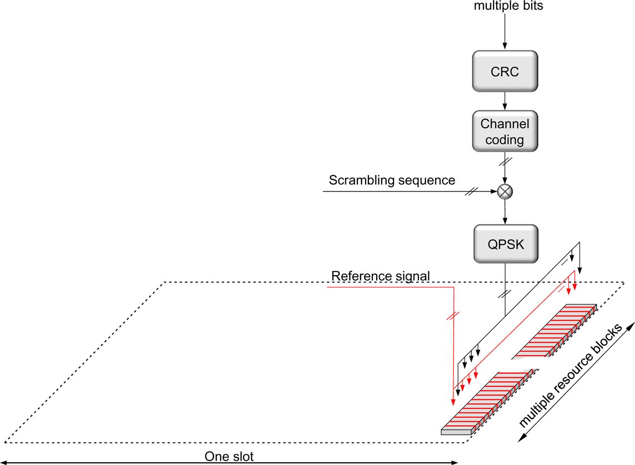
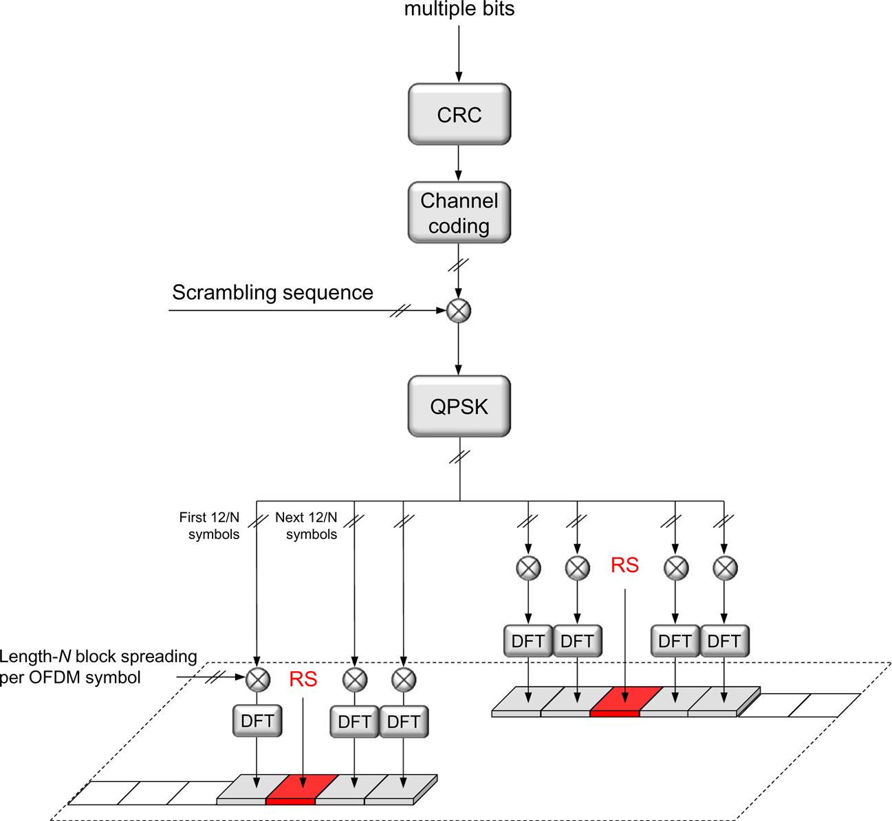
The overall transmission structure is straightforward. For larger payload sizes, a CRC is added. The control information (after CRC attachment) to be transmitted is coded, using Reed–Muller codes for payloads up to and including 11 bits and Polar4 coding for larger payloads, followed by scrambling and QPSK modulation. The scrambling sequence is based on the device identity (the C-RNTI) together with the physical-layer cell identity (or a configurable virtual cell identity), ensuring interference randomization across cells and devices using the same set of time–frequency resources. The QPSK symbols are then mapped to subcarriers across multiple resource blocks using one or two OFDM symbols. A pseudo-random QPSK sequence, mapped to every third subcarrier in each OFDM symbol, is used as a demodulation reference signal to facilitate coherent reception at the base station.
The number of resource blocks used by PUCCH format 2 is determined by the payload size and a configurable maximum code rate. The number of resource blocks is thus smaller if the payload size is smaller, keeping the effective code rate roughly constant. The number of resource blocks used is upper bounded by a configurable limit.
PUCCH format 2 is typically transmitted at the end of a slot as illustrated in Fig. 10.17. However, similarly to format 0 and for the same reasons, it is possible to transmit PUCCH format 2 also in other positions within a slot.
10.2.5 PUCCH Format 3
PUCCH format 3 can be seen as the long PUCCH counterpart to PUCCH format 2. More than two bits can be transmitted using PUCCH format 3 using from 4 to 14 symbols, each of which can be multiple resource blocks wide. Thus, it is the PUCCH format with the largest payload capacity. Similar to PUCCH format 1, the OFDM symbols used are split between symbols for control information and symbols for reference signals to allow for a low cubic metric of the resulting waveform.
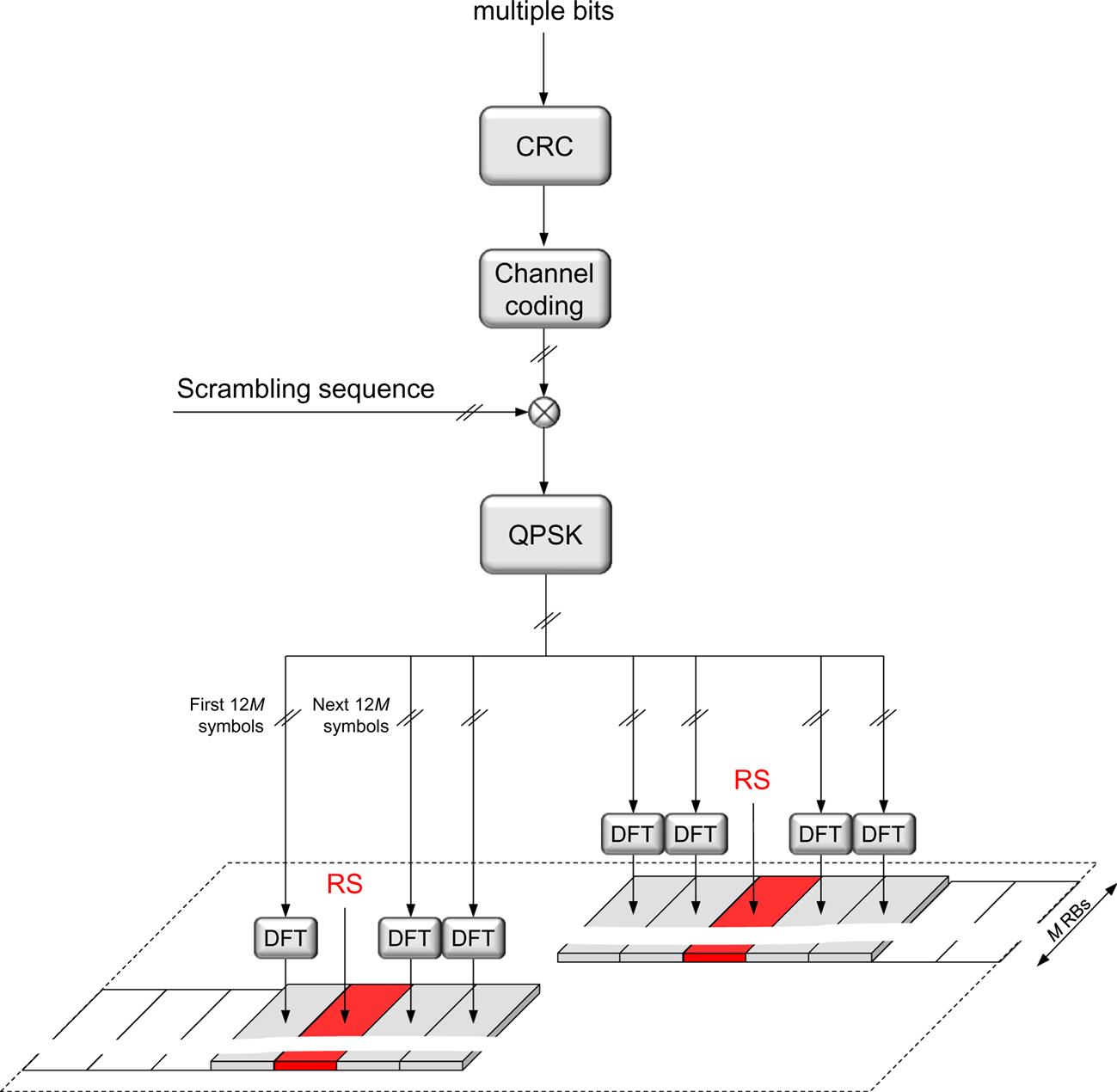
The control information to be transmitted is coded using Reed–Muller codes for 11 bits or less and Polar codes for large payloads, followed by scrambling and modulation. The scrambling sequence is based on the device identity (the C-RNTI) together with the physical-layer cell identity (or a configurable virtual cell identity), ensuring interference randomization across cells and devices using the same set of time–frequency resources. Following the principles of PUCCH format 2, a CRC is attached to the control information for the larger payloads. The modulation scheme used is QPSK but it is possible to optionally configure π/2-BPSK to lower the cubic metric at a loss in link performance.
The resulting modulation symbols are divided between the OFDM symbols. DFT precoding is applied to reduce the cubic metric and improve the power amplifier efficiency. The reference signal sequence is generated in the same way as for DFT-precoded PUSCH transmissions (see Section 9.11.2) for the same reason, namely to maintain a low cubic metric.
Frequency hopping can be configured for PUCCH format 3 as illustrated in Fig. 10.18, for example, to exploit frequency diversity, but it is also possible to operate without frequency hopping. The placements of the reference signal symbols depend on whether the frequency hopping is used or not and the length of the PUCCH transmission, as there must be at least one reference signal per hop. There is also a possibility to configure additional reference signal locations for the longer PUCCH durations to get two reference signal instances per hop.
The mapping of the UCI is such that the more critical bits, that is, hybrid-ARQ acknowledgments, scheduling request, and CSI part 1, are jointly coded and mapped close to the DM-RS locations, while the less critical bits are mapped in the remaining positions.
10.2.6 PUCCH Format 4
PUCCH format 4 (see Fig. 10.19) is in essence the same as PUCCH format 3 but with the possibility to code-multiplex multiple devices in the same resource and using at most one resource block in the frequency domain. Each control-information-carrying OFDM symbol carries 12/NSF unique modulation symbols. Prior to DFT-precoding, each modulation symbol is block-spread with an orthogonal sequence of length NSF. Spreading factors two and four are supported, implying a multiplexing capacity of two or four devices on the same set of resource blocks.
10.2.7 Resources and Parameters for PUCCH Transmission
In the discussion of the different PUCCH formats above, a number of parameters were assumed to be known. For example, the resource blocks to map the transmitted signal to, the initial phase rotation for PUCCH format 0, whether to use frequency hopping or not, and the length in OFDM symbols for the PUCCH transmission. Furthermore, the device also needs to know which of the PUCCH formats to use, and which time–frequency resources to use.
In LTE, especially in the first releases, there is a fairly fixed linkage between the uplink control information, the PUCCH format, and the transmission parameters. For example, LTE PUCCH format 1a/1b is used for hybrid-ARQ acknowledgments and the time–frequency-code resources to use are given by a fixed time offset from the reception of the downlink scheduling assignment and the resources used for the downlink assignment. This is a low-overhead solution, but has the drawback of being inflexible and was extended to provide more flexibility in later releases of LTE supporting carrier aggregation and other more advanced features.
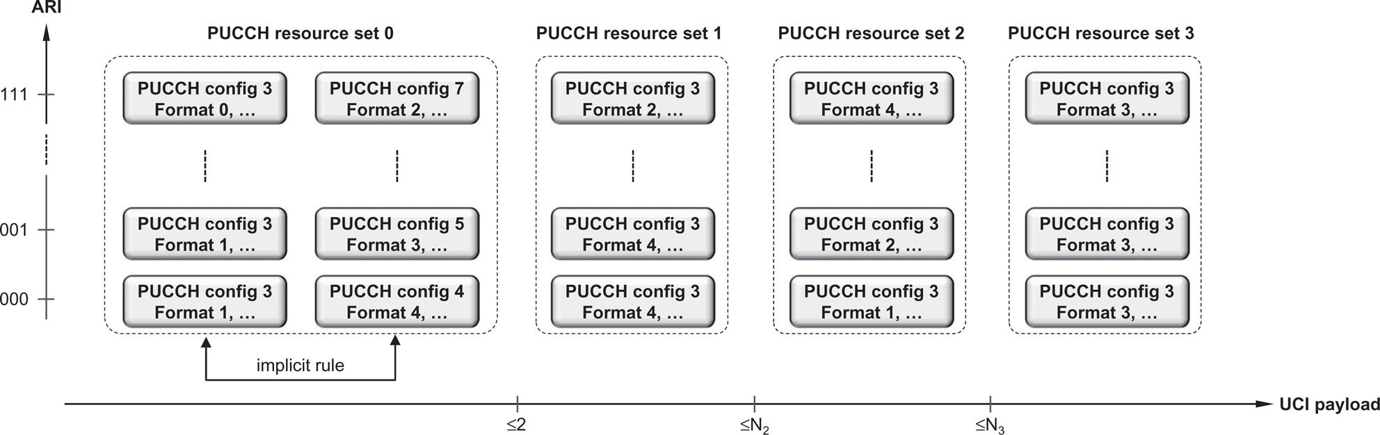
NR has adopted a more flexible scheme from the beginning, which is necessary given the very flexible framework with a wide range of service requirements in terms of latency and spectral efficiency, support of no predefined uplink–downlink allocation in TDD, different devices supporting aggregation of different number of carriers, and different antenna schemes requiring different amounts of feedback just to name some motivations. Central in this scheme is the notion of PUCCH resource sets. A PUCCH resource set contains at least four PUCCH resource configurations, where each resource configuration contains the PUCCH format to use and all the parameters necessary for that format. Up to four PUCCH resource sets can be configured, each of them corresponding to a certain range of UCI feedback to transmit. PUCCH resource set 0 can handle UCI payloads up to two bits and hence only contain PUCCH formats 0 and 1, while the remaining PUCCH resource sets may contain any PUCCH format except format 0 and 1.
When the device is about to transmit UCI, the UCI payload determines the PUCCH resource set and the ARI in the DCI determines the PUCCH resource configuration within the PUCCH resource set (see Fig. 10.20). Thus, the scheduler has control of where the uplink control information is transmitted. For periodic CSI reports and scheduling request opportunities, which both are semistatically configured, the PUCCH resources are provided as part of the CSI or SR configuration.
10.2.8 Uplink Control Signaling on PUSCH
If the device is transmitting data on PUSCH—that is, has a valid scheduling grant—simultaneous control signaling could in principle remain on the PUCCH. However, as already discussed, this is not the case as in many cases it is preferable to multiplex data and control on PUSCH and avoid a simultaneous PUCCH. One reason is the increased cubic metric compared to UCI on PUSCH when using DFT-precoded OFDM. Another reason is the more challenging RF implementation if out-of-band emission requirements should be met at higher transmission powers and with PUSCH and PUCCH widely separate in the frequency domain. Hence, similar to LTE, UCI on PUSCH is the main mechanism for simultaneous transmission of UCI and uplink data. The same principles are used for both OFDM and DFT-precoded OFDM in the uplink.
Only hybrid-ARQ acknowledgments and CSI reports are rerouted to the PUSCH. There is no need to request a scheduling grant when the device is already scheduled; instead, in-band buffer-status reports can be sent as described in Section 14.2.3.
In principle, the base station knows when to expect a hybrid-ARQ acknowledgment from the device and can therefore perform the appropriate demultiplexing of the acknowledgment and the data part. However, there is a certain probability that the device has missed the scheduling assignment on the downlink control channel. In this case the base station would expect a hybrid-ARQ acknowledgment while the device will not transmit one. If the rate-matching pattern would depend on whether an acknowledgment is transmitted or not, all the coded bits transmitted in the data part could be affected by a missed assignment and are likely to cause the UL-SCH decoding to fail.
One possibility to avoid this error is to puncture hybrid-ARQ acknowledgments onto the coded UL-SCH stream in which case the non-punctured bits are unaffected by the presence/absence of hybrid-ARQ acknowledgments. This is also the solution adopted in LTE. However, given the potentially large number of acknowledgment bits due to, for example, carrier aggregation of the use of codeblock group retransmissions, puncturing is less suitable as a general solution. Instead, NR has adopted a scheme where up to two hybrid-ARQ acknowledgment bits are punctured, while for a larger number of bits rate matching of the uplink data is used. To avoid the aforementioned error cases, the uplink DAI field in the DCI indicates the amount of resources reserved for uplink hybrid ARQ. Thus, regardless of whether the device missed any previous scheduling assignments or not, the amount of resources to use for the uplink hybrid-ARQ feedback is known.
The mapping of the UCI is such that the more critical bits, that is, hybrid-ARQ acknowledgments, are mapped to the first OFDM symbol after the first demodulation reference signal. Less critical bits, that is CSI reports, are mapped to subsequent symbols.
Unlike the data part, which relies on rate adaptation to handle different radio conditions, this cannot be used for the L1/L2 control-signaling part. Power control could, in principle, be used as an alternative, but this would imply rapid power variations in the time domain, which negatively impact the RF properties. Therefore, the transmission power is kept constant over the PUSCH duration and the amount of resource elements allocated to L1/L2 control signaling—that is, the code rate of the control signaling—is varied. In addition to a semistatic value controlling the amount of PUSCH resources used for UCI, it is also possible to signal this fraction as part of the DCI should a tight control be needed.